Arduino MKR WiFi 1010 - Servo Motor
Control precise angular motion with servo motors and your Arduino MKR WiFi 1010! Servo motors provide accurate position control from 0° to 180°, perfect for robotic arms, camera gimbals, steering mechanisms, and any project requiring controlled rotational movement. Learn to command exact angles with simple Arduino code.
What You'll Learn:
- Connecting servo motors to Arduino MKR WiFi 1010 digital pins
- Programming Arduino MKR WiFi 1010 to control servo angles (0-180°)
- Using Arduino MKR WiFi 1010 Servo library for position control
- Understanding PWM signals for Arduino MKR WiFi 1010 servo communication
- Implementing smooth servo movements with Arduino MKR WiFi 1010
- Powering servos safely with Arduino MKR WiFi 1010 projects
- Creating precise positioning systems using Arduino MKR WiFi 1010 servos
Real-World Applications:
- Robotic arms: Arduino MKR WiFi 1010 controlling multi-axis servo joints
- Camera gimbals: Arduino MKR WiFi 1010 servo motors for pan/tilt mechanisms
- Automated doors: Arduino MKR WiFi 1010 with servos for small door/lid control
- RC vehicles: Arduino MKR WiFi 1010 servo steering for remote-controlled cars
- Solar trackers: Arduino MKR WiFi 1010 positioning solar panels toward sun
- Animatronics: Arduino MKR WiFi 1010 servos creating lifelike movements
- Smart locks: Arduino MKR WiFi 1010 with servos for electronic latch control
Hardware Preparation
| 1 | × | Arduino MKR WiFi 1010 | |
| 1 | × | Micro USB Cable | |
| 1 | × | Servo Motor | |
| 1 | × | Breadboard | |
| 1 | × | Jumper Wires | |
| 1 | × | Optionally, DC Power Jack |
Or you can buy the following kits:
| 1 | × | DIYables Sensor Kit (18 sensors/displays) |
Additionally, some of these links are for products from our own brand, DIYables .
Buy Note: For controlling multiple servo motors, use the PCA9685 16 Channel PWM Servo Driver Module to save MCU pins and simplify wiring.
Overview of Servo Motor
A servo motor is a precision rotary actuator that can accurately move to and hold a specific angular position. Unlike continuous rotation motors (DC motors), standard hobby servos rotate through a limited range—typically 0° to 180°—making them perfect for precise positioning tasks.
What Makes Servos Special:
- Built-in feedback control: Internal potentiometer measures shaft position
- Self-correcting: Automatically adjusts to maintain commanded angle
- Precise positioning: Can hold a specific angle with high accuracy
- Easy control: Single PWM signal controls position (no complex drivers needed)
- Integrated gearbox: High torque at low speeds
- Compact design: Power, ground, and signal in one package
Why Use Servo Motors?
- Position control: Need exact angles, not just speed
- Holding torque: Maintains position against external forces
- Simple interface: Arduino Servo library handles PWM timing
- Wide availability: Standard hobby servos are cheap and reliable
- Immediate response: Moves to commanded position quickly
Common Servo Types:
- Standard (180°): Most common, rotates 0-180° (this tutorial)
- Continuous rotation: Modified servos that spin continuously (like DC motors)
- Digital servos: Higher precision and faster response (more expensive)
- High-torque servos: Stronger motors for heavy loads
Typical Specifications:
- Rotation range: 0° to 180° (standard), some go to 270°
- Torque: 1-10 kg·cm (larger = stronger)
- Speed: 0.1-0.2 sec/60° (how fast it rotates)
- Voltage: 4.8V-6V (5V is standard)
- Current: 100mA-2A (depends on load)
Servo Motor Pinout
Servo motors have a standardized three-wire connection with color-coded wires:
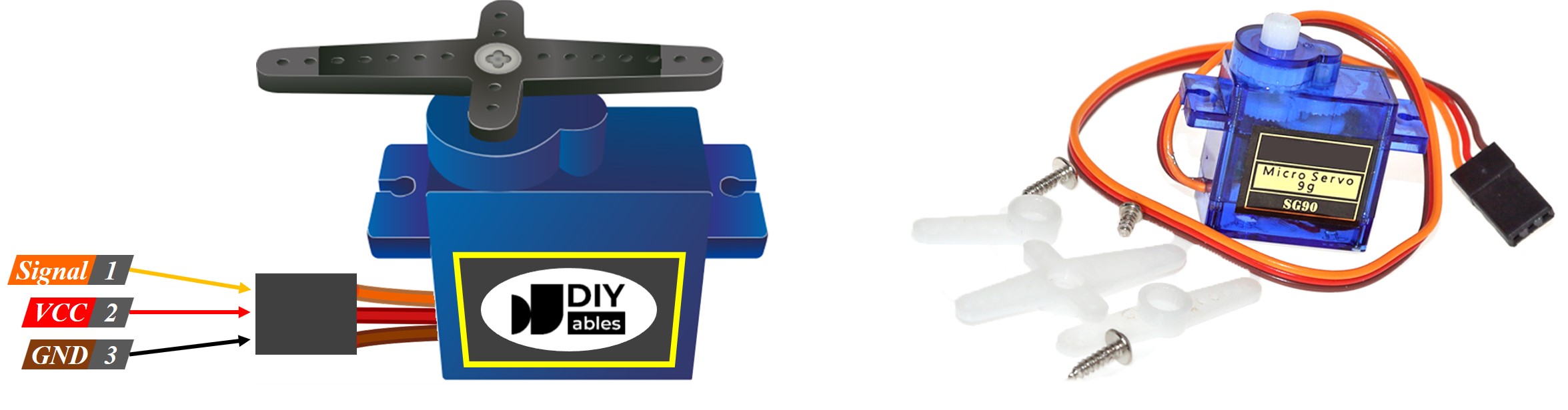
Pin 1 - GND (Ground):
- Wire color: Brown or black
- Connection: Connect to Arduino MKR WiFi 1010 GND pin
- Purpose: Completes the electrical circuit (0V reference)
Pin 2 - VCC (Power Supply):
- Wire color: Red
- Connection: Connect to external 5V power supply (recommended for multiple/high-torque servos)
- Alternative: Arduino 5V pin for small servos (with caution—see power notes below)
- Voltage: Typically 4.8V-6V (5V is standard)
- Current: 100mA-2A depending on servo size and load
Pin 3 - Signal (PWM Control):
- Wire color: Yellow, orange, or white
- Connection: Connect to Arduino MKR WiFi 1010 digital pin (any pin works, commonly D9)
- Purpose: Receives PWM control signal to set servo angle
- Signal type: 50Hz PWM with pulse width 1000-2000µs
Wire Color Variations:
Different manufacturers use slightly different color schemes:
| Manufacturer | GND | VCC | Signal |
|---|---|---|---|
| Standard | Brown | Red | Orange/Yellow |
| Hitec | Black | Red | Yellow |
| Futaba | Black | Red | White |
Important Note: While wire colors vary, the physical pin order on the connector is always standardized (GND, VCC, Signal from left to right when viewing the connector tab-side up).
How Servo Motor Works
Servo motors use a closed-loop feedback system to achieve precise position control. Understanding this mechanism helps you use them effectively.
Internal Components:
- DC Motor: Provides rotational power
- Gearbox: Reduces speed and increases torque (typically 50:1 to 300:1 ratio)
- Potentiometer: Measures actual shaft angle (feedback sensor)
- Control Circuit: Compares commanded position with actual position
- Housing: Protects internals and provides mounting points
PWM Control Signal:
Servos are controlled by a 50Hz PWM signal (pulse every 20ms). The pulse width determines the angle:
| Pulse Width | Servo Angle | Typical Use |
|---|---|---|
| 1000µs (1ms) | 0° | Fully counterclockwise |
| 1500µs (1.5ms) | 90° | Center position |
| 2000µs (2ms) | 180° | Fully clockwise |
| 1250µs | 45° | Quarter rotation |
| 1750µs | 135° | Three-quarter rotation |
How Position Control Works:
- Arduino sends PWM signal with specific pulse width
- Servo's control circuit decodes pulse width into target angle
- Internal potentiometer measures current shaft angle
- If current angle ≠ target angle, motor rotates
- As shaft moves, potentiometer value changes
- When current angle = target angle, motor stops
- Servo actively holds position (resists external forces)
Key Characteristics:
- Proportional control: Pulse width directly maps to angle
- Active holding: Servo applies torque to maintain position
- Self-correcting: If you manually push the shaft, servo fights back to return to commanded angle
- No calibration needed: Works immediately with standard pulse widths
Arduino Servo Library:
The Arduino Servo library handles all PWM timing automatically:
For a deeper dive into servo mechanics, see: How servo motor works
Wiring Diagram between Servo Motor and Arduino MKR WiFi 1010
Configuration 1: USB Power (Small Servos Only)
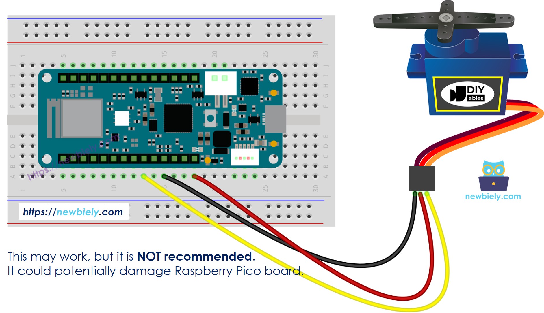
This image is created using Fritzing. Click to enlarge image
Connections:
- Servo GND (brown/black) → Arduino GND
- Servo VCC (red) → External 5V power supply (+)
- Servo Signal (yellow/orange) → Arduino digital pin (e.g., D9)
- External power GND → Arduino GND (common ground essential!)
Use this when:
- Testing with one small servo (SG90, 9g micro servo)
- Servo draws <500mA current
- No heavy loads on servo
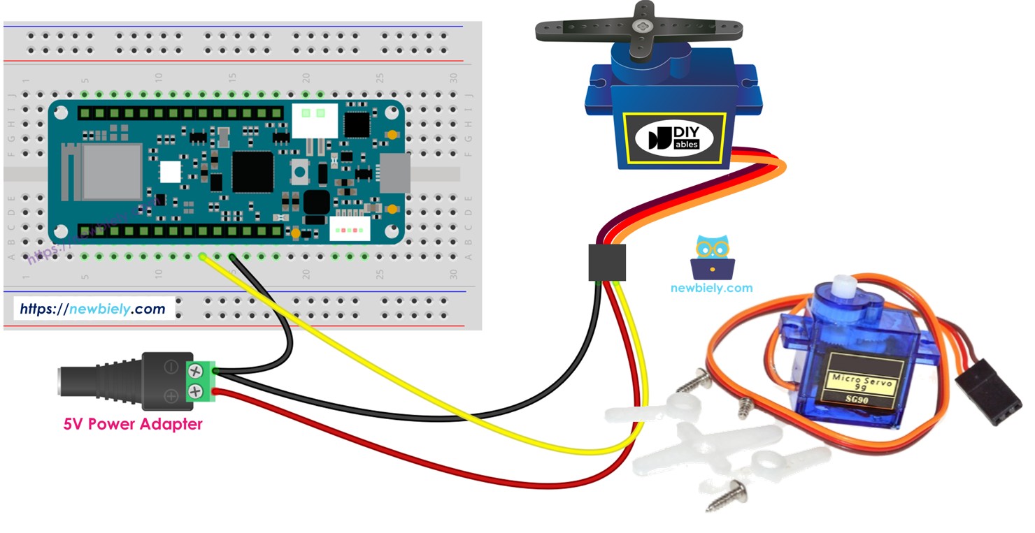
Configuration 2: External Power Supply (Recommended)
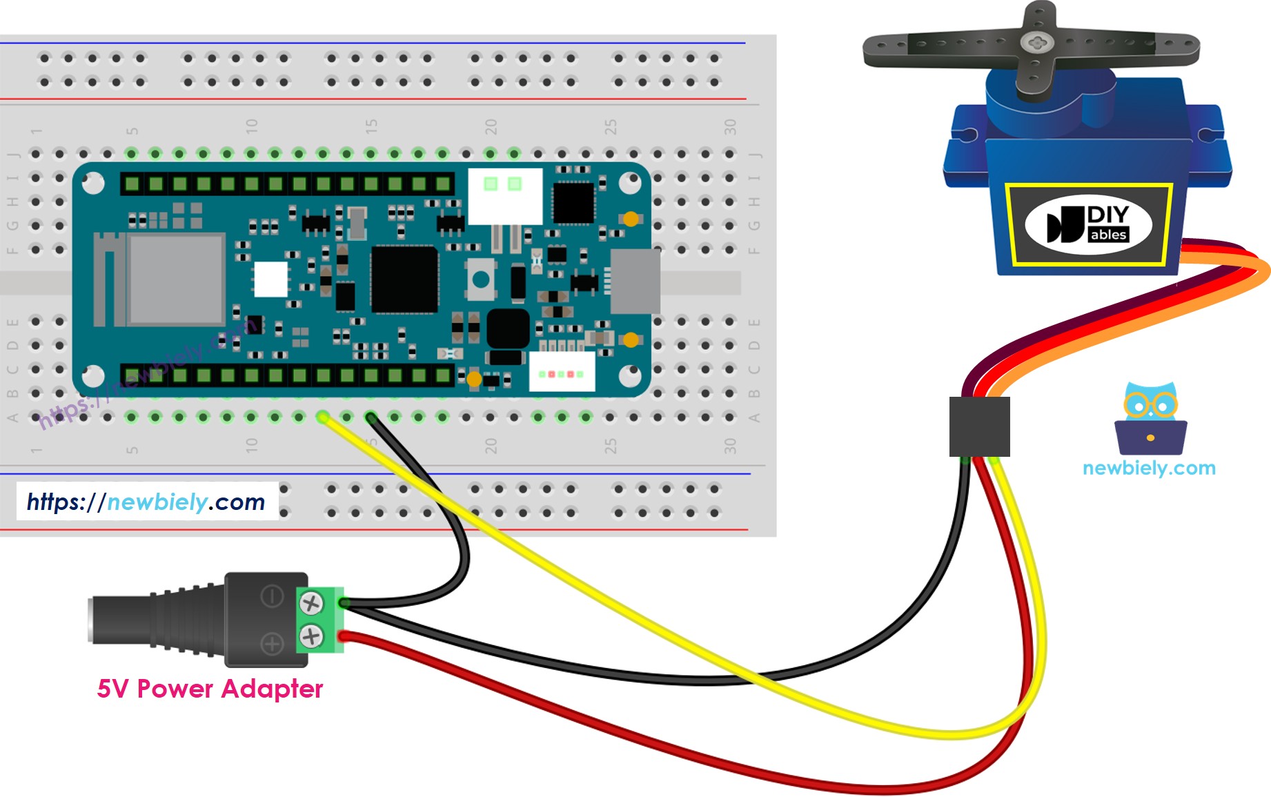
This image is created using Fritzing. Click to enlarge image
Connections:
- Servo GND → External 5V power supply (-)
- Servo VCC → External 5V power supply (+)
- Servo Signal → Arduino digital pin (e.g., D9)
- External power GND → Arduino GND (critical: common ground!)
- Arduino powered separately via USB or Vin
Use this when:
- Using multiple servos (2 or more)
- Using high-torque servos (MG996R, standard-size servos)
- Servos under heavy load
- Professional/reliable projects
※ NOTE THAT:
CRITICAL POWER SAFETY:
⚠ WARNING - Board Damage Risk:
- NEVER power servos from Vin or VBUS pins when Arduino is USB-powered!
- USB ports provide limited current (~500mA max)
- Servos can draw 1-2A, especially under load or during rapid movements
- Exceeding current limit can:
- Damage your computer's USB port
- Burn out Arduino voltage regulator
- Cause Arduino to reset randomly
- Permanently damage the board
- External 5V supply (battery pack, wall adapter) → Safest for servos
- Arduino 5V pin → Only for tiny servos (SG90), no load, testing only
- Common ground mandatory → Always connect power supply GND to Arduino GND
- SG90 micro servo: 100-250mA (can work from Arduino temporarily)
- Standard servo (MG996R): 500mA-2A (needs external power)
- Multiple servos: Add currents, use external supply
- 4× AA battery pack (6V) with 5V regulator
- USB power bank (5V, 2A+)
- 5V wall adapter (2A minimum)
Safe Power Options:
Current Requirements:
Recommended External Supply:
Arduino MKR WiFi 1010 Code
Detailed Instructions
New to Arduino MKR WiFi 1010? Complete our Getting Started with Arduino MKR WiFi 1010 tutorial first to set up your development environment.
Step 1: Wire the Hardware
- Connect servo motor to Arduino MKR WiFi 1010 as shown in wiring diagram above
- Use external 5V power supply for servo VCC (recommended)
- Connect servo Signal wire to Arduino digital pin D9
- Ensure common ground: Connect external power GND to Arduino GND
Step 2: Program the Board
- Plug your Arduino MKR WiFi 1010 into your computer's USB port
- Launch the Arduino IDE on your computer
- Select the Arduino MKR WiFi 1010 board and its COM port
- Copy the code above and paste it into the Arduino IDE
- Click the Upload button to compile and upload the code
Step 3: Observe Servo Movement
- Watch the servo motor sweep smoothly from 0° to 180° (right)
- Then sweep back from 180° to 0° (left)
- Movement repeats continuously
- Notice the smooth incremental motion (not instant jumps)
Troubleshooting:
- Servo jitters/vibrates: Check power supply, ensure sufficient current
- Servo doesn't move: Verify signal wire connection, check power
- Random resets: Servo drawing too much current—use external power
- Servo moves wrong direction: Normal variation—adjust code angles
Code Explanation
Let's break down how the Arduino MKR WiFi 1010 controls the servo motor:
Library and Object Creation:
- Includes Arduino Servo library (handles PWM timing)
- Creates servo object named myServo
- Can create multiple servo objects for multiple servos
Setup - Attach Servo:
- attach(pin) configures pin 14 to output servo PWM signals
- Arduino now sends 50Hz PWM pulses to control servo position
- Pin can be any digital pin on Arduino MKR WiFi 1010
Loop - Sweep Right (0° to 180°):
- Loop increments angle from 0 to 180 (1° per iteration)
- write(angle) commands servo to move to specified angle
- delay(15) creates 15ms pause between steps
- Total sweep time: 180 steps × 15ms = 2.7 seconds
- Creates smooth, slow motion
Loop - Sweep Left (180° to 0°):
- Loop decrements angle from 180 back to 0
- Reverses direction smoothly
- Same timing for symmetrical motion
Key Concepts:
- write() method: Commands servo to move to angle (0-180)
- Incremental movement: Small steps create smooth motion
- Delay controls speed: Smaller delay = faster movement, larger delay = slower
- Continuous loop: Servo sweeps back and forth endlessly
Servo Library Methods:
How to Control Speed of Servo Motor
Servo motors don't have direct speed control—they move as fast as possible to the commanded position. However, you can create the illusion of speed control by moving in small increments with delays:
Slower Movement (Larger Delay):
Faster Movement (Smaller Delay):
Instant Movement (No Loop):
Advanced: Acceleration/Deceleration:
For more advanced speed control techniques, see: How to control speed of servo motor
Challenge Yourself
Ready to explore more with your Arduino MKR WiFi 1010 and servo motors? Try these creative experiments:
- Potentiometer Control: Connect a potentiometer to analog pin—map its value (0-1023) to servo angle (0-180°). Create a manual servo controller.
- Button Positions: Use 3 buttons to move servo to preset positions: Button1=0°, Button2=90°, Button3=180°.
- Smooth Acceleration: Modify the sweep code to accelerate at the start and decelerate at the end (ease-in/ease-out motion).
- Multi-Servo Control: Connect 3 servos to different pins. Create a coordinated dance routine with synchronized movements.
- Sensor-Triggered Servo: Use an ultrasonic distance sensor—servo angle represents distance (close=0°, far=180°). Create a distance indicator.
- Servo Sequencer: Create a sequence of 10 different positions with different speeds. Store in arrays and loop through them.
- Web-Controlled Servo: Combine with WiFi capabilities—control servo angle from a web browser (see video below for inspiration).
- Robotic Gripper: Build a simple gripper mechanism—use servo to open/close based on button press or sensor input.