Arduino MKR WiFi 1010 - Relay
Control high-voltage devices safely with your Arduino MKR WiFi 1010 and relays! This tutorial teaches you how to use relays with Arduino MKR WiFi 1010 to control pumps, lights, motors, and high-power devices. Learn how to wire relays to your Arduino MKR WiFi 1010, understand normally open and normally closed modes, program Arduino MKR WiFi 1010 to switch relays on and off, and build automation projects. Perfect for creating Arduino MKR WiFi 1010 home automation systems, security devices, and smart power control projects.
What You'll Learn
- Connecting relays to your Arduino MKR WiFi 1010 safely
- Understanding relay operation with Arduino MKR WiFi 1010
- Programming Arduino MKR WiFi 1010 to control relays
- Wiring high-voltage devices through Arduino MKR WiFi 1010 relays
- Using normally open and normally closed modes on Arduino MKR WiFi 1010
- Controlling 12V and 24V devices with Arduino MKR WiFi 1010
- Building automation projects using Arduino MKR WiFi 1010 relay control
Real-World Applications
- Home automation: Control lights and fans with Arduino MKR WiFi 1010 relays
- Garden watering: Automate pumps using Arduino MKR WiFi 1010 relay control
- Security systems: Lock control with Arduino MKR WiFi 1010 and relays
- Temperature control: Switch heaters with Arduino MKR WiFi 1010 automation
- Motor control: Start and stop motors using Arduino MKR WiFi 1010
- Smart plugs: WiFi-controlled outlets with Arduino MKR WiFi 1010
- Aquarium control: Manage devices with Arduino MKR WiFi 1010 relay timing
Relays are essential for Arduino MKR WiFi 1010 projects that control real-world devices!
Hardware Preparation
| 1 | × | Arduino MKR WiFi 1010 | |
| 1 | × | Micro USB Cable | |
| 1 | × | Relay | |
| 1 | × | LED Strip | |
| 1 | × | 12V Power Adapter | |
| 1 | × | Breadboard | |
| 1 | × | Jumper Wires | |
| 1 | × | Optionally, DC Power Jack |
Or you can buy the following kits:
| 1 | × | DIYables Sensor Kit (18 sensors/displays) |
Additionally, some of these links are for products from our own brand, DIYables .
Overview of Relay
A relay is an electrically controlled switch that allows your Arduino MKR WiFi 1010 (which operates at low voltage/current) to safely control high-voltage, high-current devices like pumps, motors, heaters, and lights.
SAFETY WARNING:
- High voltage can cause serious injury or death
- Only work with high voltage if you have proper training and experience
- We strongly recommend using DC devices rated at 24V or less
- Never work with AC mains voltage (110V/220V) unless you are a qualified electrician
- Always double-check wiring before applying power
Relay Pinout
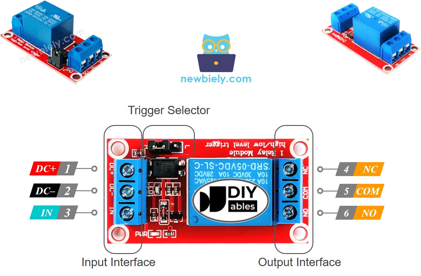
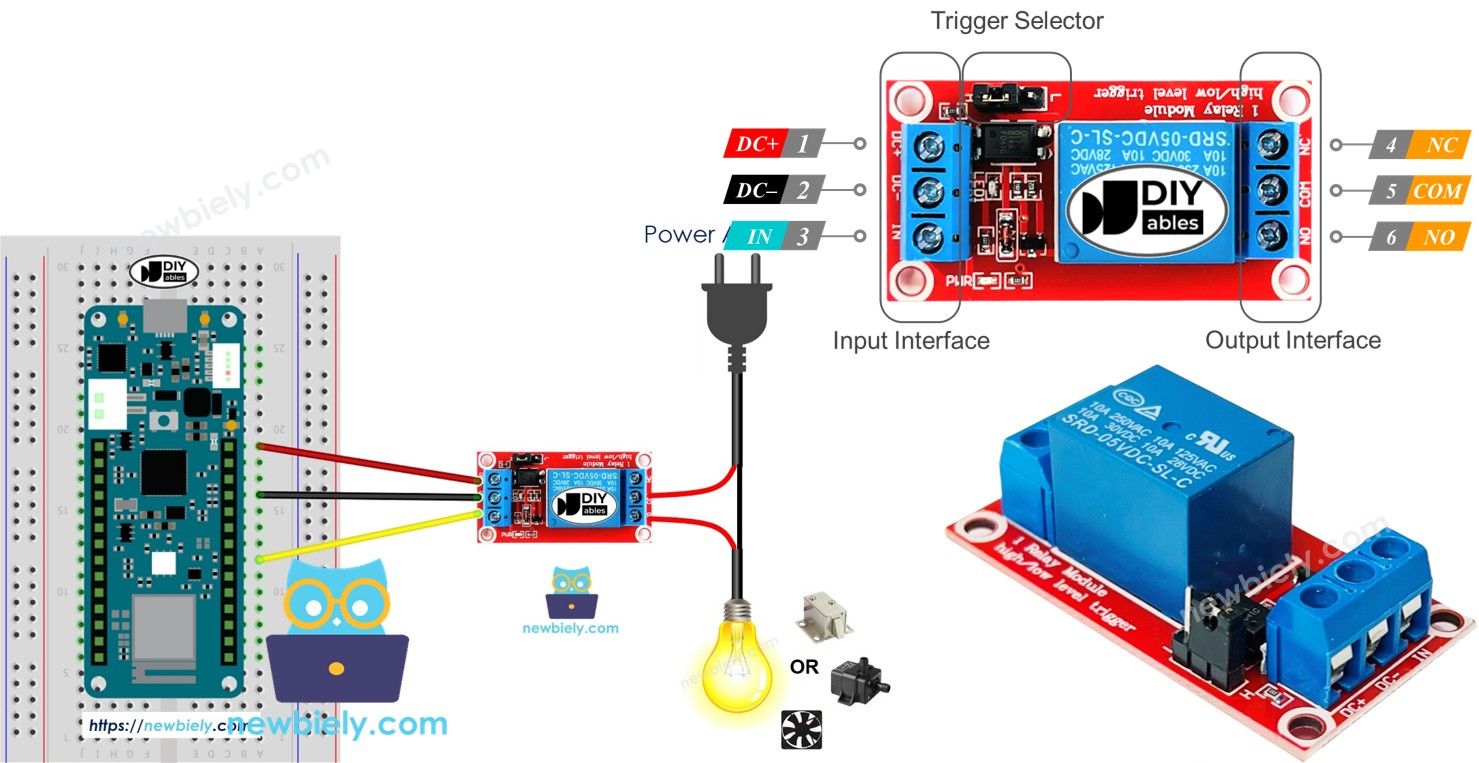
A relay module has two sets of terminals:
Input Terminals (Low Voltage - Connect to Arduino MKR WiFi 1010):
- DC-: Connect to GND (ground)
- DC+: Connect to VCC (5V power)
- IN: Connect to any digital output pin on your Arduino MKR WiFi 1010 for control
Output Terminals (High Voltage - Connect to Device):
- COM (Common): Always used - connects to one side of your device's power
- NO (Normally Open): Disconnected from COM when relay is OFF, connected when relay is ON
- NC (Normally Closed): Connected to COM when relay is OFF, disconnected when relay is ON
Note: Pin order varies by manufacturer - always check the labels on your specific relay module!
Most relay modules also have a jumper to select trigger mode (high-level or low-level trigger).
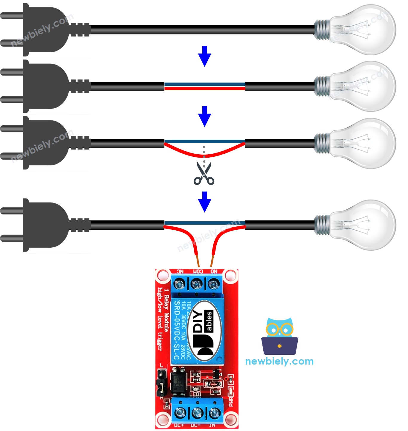
How to Connect a High-Voltage Device to Relay
Connect your device's power wire through the relay terminals:
- Normally Open Mode: Device is OFF by default. Use COM and NO terminals.
- Normally Closed Mode: Device is ON by default. Use COM and NC terminals.
How Relay Works
Relays have two configuration options:
1. Output Mode (Hardware wiring):
- Normally Open (NO): Device is OFF when relay is inactive, ON when relay is activated
- Normally Closed (NC): Device is ON when relay is inactive, OFF when relay is activated
2. Trigger Mode (Signal level):
- Low-Level Trigger: Relay activates when IN pin receives LOW (0V) signal
- High-Level Trigger: Relay activates when IN pin receives HIGH (5V) signal
Important Notes:
- Most relay modules support both NO and NC modes (you choose via wiring)
- Not all relay modules support both trigger modes (check your module's specifications)
- "Normally" refers to the relay state when the IN pin is LOW
- The trigger mode is usually set with a jumper on the relay module
Combining input modes and output modes gives you many ways to use it. If you're just starting out, we suggest using HIGH level trigger mode and normally open mode.
Because the LOW level trigger and HIGH level trigger modes work in opposite directions, we will explain the HIGH level trigger mode in detail next. The LOW level trigger mode works the other way.
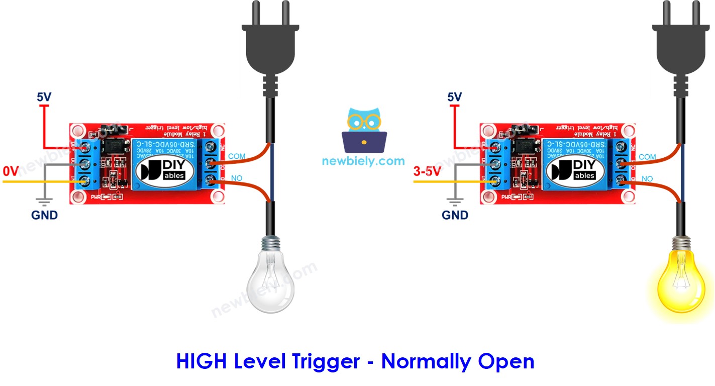
HIGH Level Trigger - Normally Open Mode
Connect the high-power device to the COM pin and the NO pin. It works just like a switch:
- When the IN pin is at LOW (0V), the switch is open and the device is turned off.
- When the IN pin is at HIGH (5V or 3.3V), the switch is closed and the device is turned on.
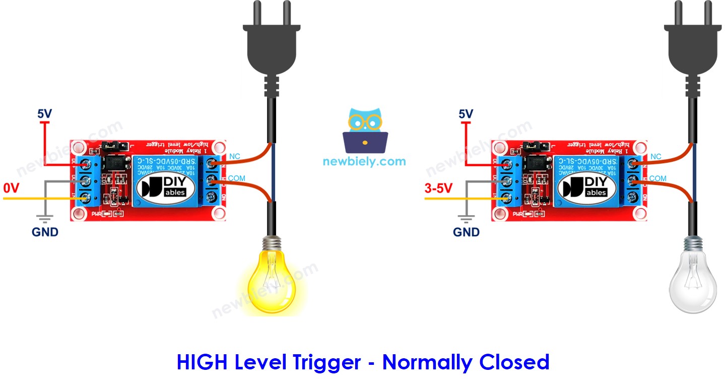
HIGH Level Trigger - Normally Closed Mode
Connect the high-voltage device to the COM pin and the NC pin, just like you would with a switch.
- If the IN pin is set to 0V, the switch closes and turns the device on. If the IN pin is set to 5V or 3.3V, the switch opens and turns the device off.
What option should we choose?
It depends on what you use it for.
Normally Open Mode vs Normally Closed Mode
The relay works like a switch. The table below explains the difference between the two modes in HIGH Level Trigger.
| Pins used | IN pin | Relay state | Device state | |
|---|---|---|---|---|
| Normally Open Mode | COM and NO pin | LOW | ⇒ open | ⇒ OFF |
| Normally Closed Mode | COM and NC pin | LOW | ⇒ closed | ⇒ ON |
| Normally Open Mode | COM and NO pin | HIGH | ⇒ closed | ⇒ ON |
| Normally Closed Mode | COM and NC pin | HIGH | ⇒ open | ⇒ OFF |
Arduino MKR WiFi 1010 - Relay
The Arduino MKR WiFi 1010 can control a high voltage device using a relay.
Controlling a relay is very simple. All we need is:
- Connect a pin from your Arduino MKR WiFi 1010 board to the relay's IN pin. Control the relay by changing the pin's setting to LOW or HIGH.
Wiring Diagram
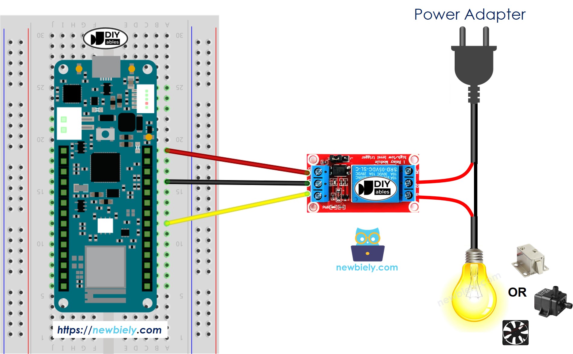
This image is created using Fritzing. Click to enlarge image
How To Program Relay using Arduino MKR WiFi 1010
- Set one of the Arduino MKR WiFi 1010 pins to work as an output by using the pinMode() function. For example, you can set pin D2 as the output pin.
- Use the digitalWrite() function to set the output pin to LOW (0 volts).
- Set the output pin to HIGH (3.3V) using the digitalWrite() function:
Arduino MKR WiFi 1010 Code
Detailed Instructions
New to Arduino MKR WiFi 1010? Complete our Getting Started with Arduino MKR WiFi 1010 tutorial first to set up your development environment.
- Wire the components according to the diagram above
- Connect the Arduino MKR WiFi 1010 to your computer via USB cable
- Open Arduino IDE and select the correct board and COM port
- Copy the code and upload it to your board
- Watch the LED strip blink on/off through relay control
Challenge Yourself
Ready to take your relay control skills further? Try these exciting projects:
- WiFi-Controlled Outlet: Use the MKR WiFi 1010's WiFi to control a relay from your phone or web browser
- Temperature-Controlled Fan: Combine a temperature sensor with a relay to automatically turn a fan on/off based on room temperature
- Automatic Plant Watering: Use a soil moisture sensor to trigger a water pump relay when plants need watering
- Light-Activated Relay: Combine a photoresistor with a relay to turn devices on at sunset and off at sunrise
- Multi-Relay Sequencer: Control 4 or 8 relays in sequence to create complex automation patterns
- Timer-Based Power Control: Create a programmable timer that turns devices on/off at scheduled times
- Remote Door Lock: Build a secure electromagnet lock controller using relay and WiFi connectivity