Arduino MKR WiFi 1010 - Joystick
Control robots, games, and projects with your Arduino MKR WiFi 1010 and a joystick! This tutorial teaches you everything about using joysticks with Arduino MKR WiFi 1010—from basic wiring to advanced movement control. Learn how to read joystick positions with your Arduino MKR WiFi 1010, detect button presses, and convert analog readings into movement commands. Perfect for building Arduino MKR WiFi 1010 robot controllers, game interfaces, or camera pan-tilt systems with intuitive joystick control.
What You'll Learn
- Connecting joysticks to your Arduino MKR WiFi 1010 correctly
- Reading X and Y analog positions with Arduino MKR WiFi 1010
- Programming Arduino MKR WiFi 1010 to detect joystick button presses
- Converting joystick values to movement commands using Arduino MKR WiFi 1010
- Building robot controls with Arduino MKR WiFi 1010 and joystick
- Creating game controllers using Arduino MKR WiFi 1010 joystick input
- Controlling servo motors with Arduino MKR WiFi 1010 joystick movements
Real-World Applications
- Robot control: Build Arduino MKR WiFi 1010 robot cars controlled by joystick movements
- Game controllers: Create custom gaming interfaces with Arduino MKR WiFi 1010 joystick input
- Camera control: Pan-tilt camera systems using Arduino MKR WiFi 1010 and joystick
- Drone controls: Design drone controllers with Arduino MKR WiFi 1010 joystick interface
- RC vehicles: Control remote cars and boats with Arduino MKR WiFi 1010 joystick commands
- Robotic arms: Position robotic arms using Arduino MKR WiFi 1010 joystick control
- Wheelchair control: Assistive devices with Arduino MKR WiFi 1010 joystick navigation
Joysticks provide intuitive 2D control perfect for Arduino MKR WiFi 1010 robotics and interactive projects!
Hardware Preparation
| 1 | × | Arduino MKR WiFi 1010 | |
| 1 | × | Micro USB Cable | |
| 1 | × | Joystick | |
| 1 | × | Breadboard | |
| 1 | × | Jumper Wires | |
| 1 | × | Optionally, DC Power Jack |
Or you can buy the following kits:
| 1 | × | DIYables Sensor Kit (18 sensors/displays) |
Additionally, some of these links are for products from our own brand, DIYables .
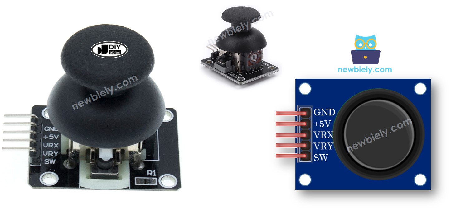
Overview of Joystick Sensor
A joystick is an input device you've probably used in video games, RC controllers, or heavy equipment like excavators. Joysticks provide intuitive 2D control by tilting in any direction—perfect for Arduino MKR WiFi 1010 projects!
How joysticks work:
- Two potentiometers arranged at 90° to each other measure tilt in X and Y directions
- One built-in pushbutton activates when you press down on the joystick
Joystick outputs:
- X-axis: Analog value (0-4095) indicating left-right position
- Y-axis: Analog value (0-4095) indicating up-down position
- Button: Digital value (HIGH/LOW) from the pushbutton
The center position (joystick at rest) produces mid-range values around 2048 for both axes. Your Arduino MKR WiFi 1010 can use all three outputs or just the ones needed for your specific project.
Pinout
Joysticks typically have five pins:
- GND pin: Connect to GND (ground/0V)
- VCC pin: Connect to 3.3V power
- VRX pin: Analog output for horizontal (X-axis) position
- VRY pin: Analog output for vertical (Y-axis) position
- SW pin: Button output (requires pull-up resistor)—HIGH when not pressed, LOW when pressed
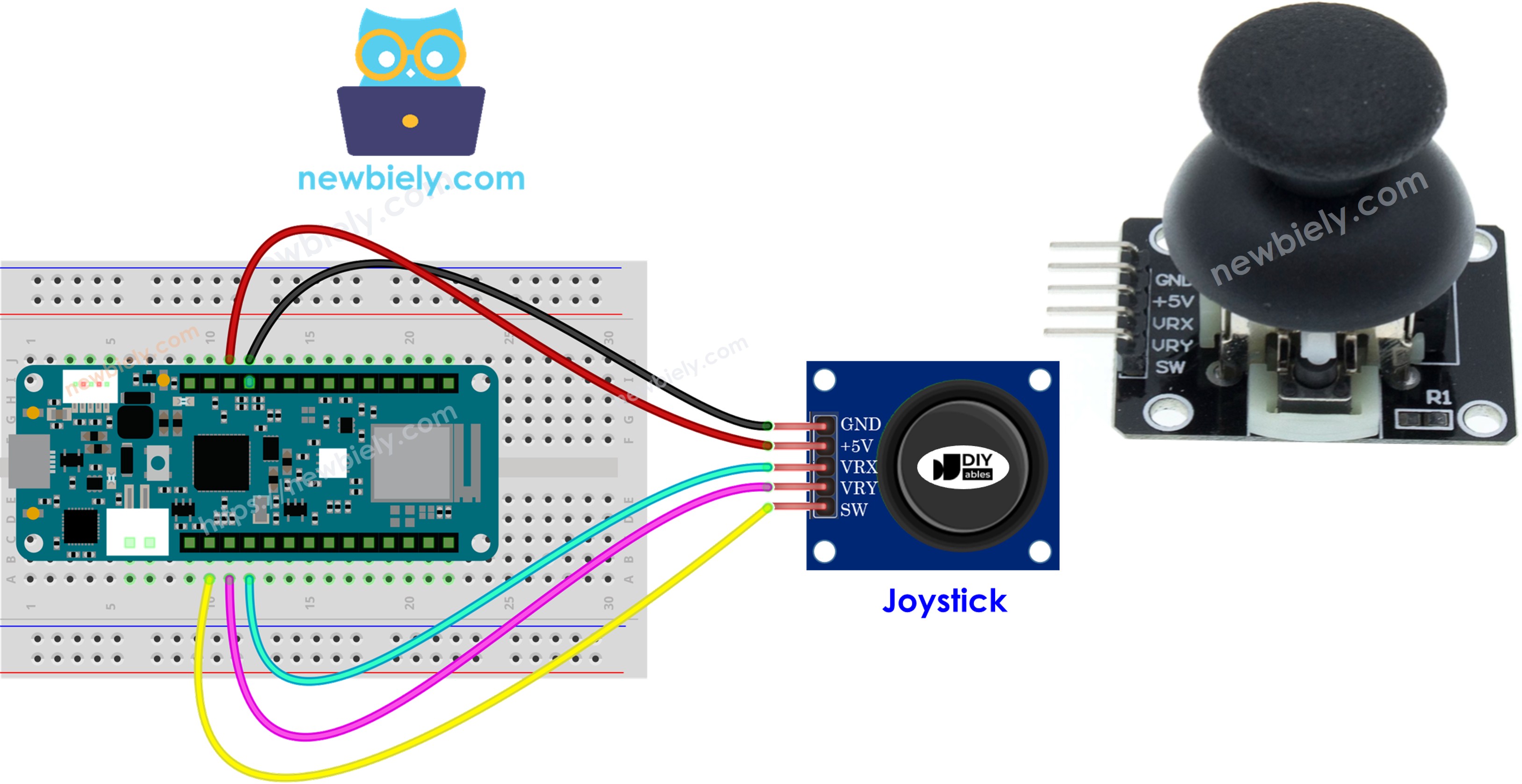
Wiring
Connect the joystick to your Arduino MKR WiFi 1010 as shown in this table:
| Joystick | Arduino MKR WiFi 1010 |
|---|---|
| GND | GND |
| VCC | 3.3V |
| VRX | A2 |
| VRY | A1 |
| SW | A0 |
How It Works
X-axis (left-right):
- Fully left: VRX = 0V → Arduino MKR WiFi 1010 reads 0
- Center: VRX = ~1.65V → Arduino MKR WiFi 1010 reads ~2048
- Fully right: VRX = 3.3V → Arduino MKR WiFi 1010 reads 4095
Y-axis (up-down):
- Fully up: VRY = 0V → Arduino MKR WiFi 1010 reads 0
- Center: VRY = ~1.65V → Arduino MKR WiFi 1010 reads ~2048
- Fully down: VRY = 3.3V → Arduino MKR WiFi 1010 reads 4095
Diagonal movement:
- Both X and Y values change simultaneously based on tilt direction
Button press:
- With pull-up resistor: SW pin goes from HIGH (3.3V) to LOW (0V) when pressed
- Arduino MKR WiFi 1010 digital pin detects the HIGH-to-LOW transition
Wiring Diagram
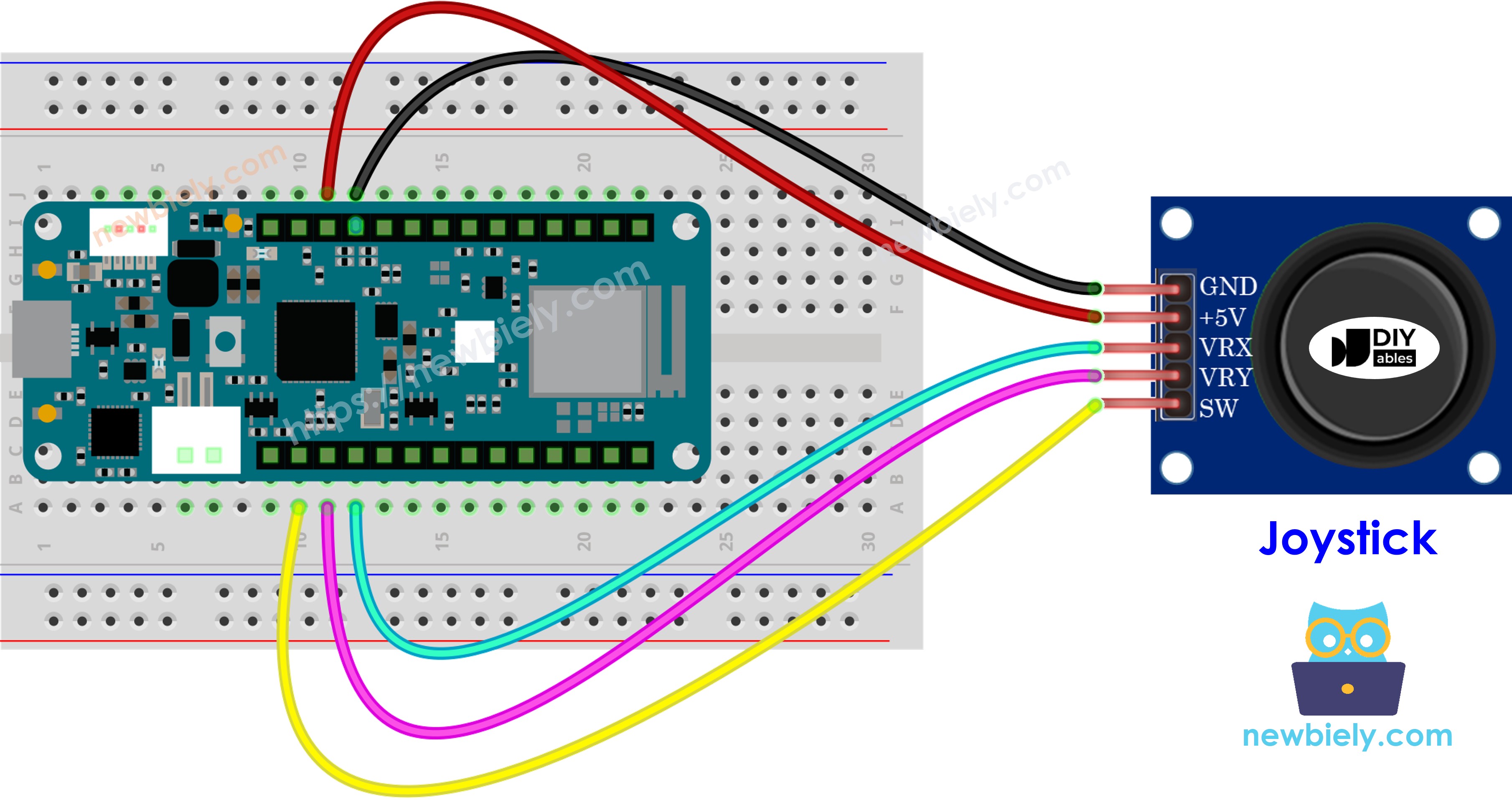
This image is created using Fritzing. Click to enlarge image
How to Program Joystick with Arduino MKR WiFi 1010
Programming a joystick involves reading two analog inputs and one digital input:
Reading analog X and Y positions:
Reading the button: Use the ezButton library for reliable button reading—it handles debouncing and enables the internal pull-up resistor automatically. See the Arduino MKR WiFi 1010 - Button tutorial for more details.
After reading raw values, you'll often convert them into useful control commands (shown in the code examples below).
Arduino MKR WiFi 1010 Code Examples
This section provides four complete examples:
- Example 1: Read raw analog values from joystick
- Example 2: Read analog values and button state
- Example 3: Convert values to movement commands (UP/DOWN/LEFT/RIGHT)
- Example 4: Convert values to servo motor angles (pan-tilt control)
Reads analog values from joystick
Detailed Instructions
New to Arduino MKR WiFi 1010? Start with our Getting Started with Arduino MKR WiFi 1010 tutorial first!
- Wire the joystick to your Arduino MKR WiFi 1010 following the wiring diagram above
- Plug your Arduino MKR WiFi 1010 into your computer's USB port
- Open the Arduino IDE and select Arduino MKR WiFi 1010 and its COM port
- Copy and paste the code above into Arduino IDE
- Click the Upload button
- Move the joystick in a circle (clockwise or counter-clockwise)
- Open the Serial Monitor to see the X and Y values change
Calibrating directions:
- Move the joystick while watching the Serial Monitor
- When X reads 0, that's the LEFT position (opposite side is RIGHT)
- When Y reads 0, that's the UP position (opposite side is DOWN)
※ NOTE THAT:
You may notice values don't exactly match joystick position—this is normal ADC behavior for the Arduino MKR WiFi 1010.
Reads analog values and reads the button state from a joystick
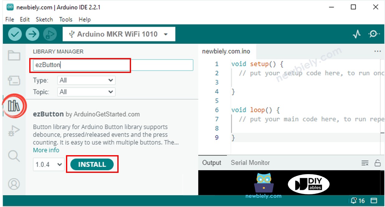
Detailed Instructions
- Open the Library Manager by clicking the icon on the left side of Arduino IDE
- Search for ezButton and find the library by ArduinoGetStarted.com
- Click Install to add the ezButton library
- Copy the code above and paste it into Arduino IDE
- Click Upload to send the code to your Arduino MKR WiFi 1010
- Move the joystick in different directions (left, right, up, down)
- Press down on the joystick to trigger the button
- Check the Serial Monitor for X, Y, and button values
Converts analog value to MOVE LEFT/RIGHT/UP/DOWN commands
Detailed Instructions
- Copy the code above and paste it into Arduino IDE
- Click Upload to send the code to Arduino MKR WiFi 1010
- Move the joystick in any direction (left, right, up, down, or diagonal)
- Check the Serial Monitor for movement commands
※ NOTE THAT:
Depending on joystick position, you may see no command, one command, or two simultaneous commands (e.g., "UP" and "LEFT" together for diagonal movement).
Converting Analog Values to Servo Motor Angles
For controlling pan-tilt systems with servo motors using your joystick, see the complete tutorial: Arduino MKR WiFi 1010 - Joystick Controls Servo Motor.
Challenge Yourself
Once you have your joystick working, try these advanced projects:
- Robot car control: Use joystick X-axis for steering and Y-axis for speed control
- LED matrix cursor: Move a pixel cursor across an LED matrix display with the joystick
- Multiple modes: Use the button to switch between different control modes
- Speed control: Map joystick distance from center to motor speed (farther = faster)
- Cursor smoothing: Add averaging to make joystick control smoother and less jittery
- Dual joysticks: Connect two joysticks for tank-style robot control (left/right tracks)
- Menu navigation: Create an LCD menu system controlled by joystick movements