Arduino MKR WiFi 1010 - Buzzer
Welcome to this guide on controlling a 12V active buzzer with your Arduino MKR WiFi 1010! Learn how to create loud, attention-grabbing alarm sounds perfect for security systems, emergency alerts, and industrial applications.
What You'll Learn:
- Understanding 12V active buzzer operation and capabilities
- Why a relay is required (and how it works)
- Proper wiring for high-voltage buzzer control
- Programming the Arduino to create alarm patterns
12V Buzzer vs 5V Piezo Buzzer - Which to Use?
- 12V Active Buzzer (this tutorial):
- Volume: Very loud (90-110 dB)
- Power: Requires 12V external supply
- Control: Needs relay switching
- Best for: Alarms, security systems, outdoor warnings, industrial alerts
- Sound: Single fixed frequency, very piercing
- 5V Piezo Buzzer (see this tutorial):
- Volume: Moderate (70-85 dB)
- Power: Works directly from Arduino
- Control: Direct connection, no relay needed
- Best for: Button feedback, simple alerts, indoor notifications
- Sound: Can play tones and melodies
- High volume: Typically 90-110 decibels (comparable to a car horn or chainsaw)
- Fixed frequency: Built-in oscillator produces one tone (cannot play melodies)
- 12V operation: Requires external power supply
- High current: Typically 30-100mA (too much for Arduino pins)
- Immediate response: Sound starts instantly when powered
- Security alarms: Intruder detection, door/window alerts
- Fire alarms: Smoke detector audible warnings
- Industrial safety: Equipment malfunction alerts
- Emergency signals: Panic buttons, evacuation warnings
- Vehicle alarms: Backup warnings, horn systems
- Positive (+) pin (red wire): Connects to the +12V output of your DC power supply. This is where the power flows in.
- Negative (-) pin (black wire): Connects to the ground (GND) of your DC power supply. This completes the circuit.
- Low-power side: Arduino controls the relay with a 3.3V signal (low current)
- High-power side: Relay switches the 12V power to the buzzer (high current)
- Arduino sends LOW signal to relay → Relay opens → Buzzer OFF
- Arduino sends HIGH signal to relay → Relay closes → Buzzer ON
- Relay control: Arduino digital pin → Relay IN (signal) pin
- Relay power: Arduino 5V → Relay VCC, Arduino GND → Relay GND
- Buzzer circuit: 12V power supply (+) → Relay COM terminal
- Buzzer connection: Relay NO (Normally Open) → Buzzer (+) red wire
- Return path: Buzzer (-) black wire → 12V power supply GND
- Common ground: Connect Arduino GND and 12V supply GND together
- Assemble the circuit - Connect all components following the wiring diagram above. Triple-check power connections before applying power!
- Connect to computer - Use a Micro USB cable to connect the Arduino MKR WiFi 1010 to your computer.
- Open Arduino IDE - Launch the Arduino IDE application.
- Select board and port - Choose Arduino MKR WiFi 1010 and select the appropriate COM port.
- Load the code - Copy the complete code above and paste it into the Arduino IDE.
- Upload - Click the Upload button to transfer the code.
- Test the buzzer - The buzzer should start beeping loudly in the programmed pattern. Warning: It's LOUD! Have your fingers ready to disconnect power if needed in a quiet environment.
- Setup: Configure the relay control pin as OUTPUT
- Loop:
- Change timing for different alarm patterns (rapid beep: 100ms on, 100ms off)
- Add button control to activate/deactivate the alarm
- Combine with sensors (motion, door, temperature) for automatic triggering
- Create Morse code patterns by varying on/off durations
- Implement different patterns for different alert types
Rule of Thumb: Need to wake someone across the house or outdoors? Use 12V. Need simple UI feedback? Use 5V piezo.
Hardware Preparation
| 1 | × | Arduino MKR WiFi 1010 | |
| 1 | × | Micro USB Cable | |
| 1 | × | Relay | |
| 1 | × | 12V Active Buzzer | |
| 1 | × | 12V Power Adapter | |
| 1 | × | Optionally, DC Power Jack | |
| 1 | × | Breadboard | |
| 1 | × | Jumper Wires |
Or you can buy the following kits:
| 1 | × | DIYables Sensor Kit (18 sensors/displays) |
Additionally, some of these links are for products from our own brand, DIYables .
Overview of 12V Active Buzzer
A 12V active buzzer is a high-power audio output device designed for applications requiring loud, attention-grabbing sound. The term "active" means it has internal oscillator circuitry—you simply apply power, and it produces a loud, continuous tone at a fixed frequency.
Key Characteristics:
Common Applications:
Pinout
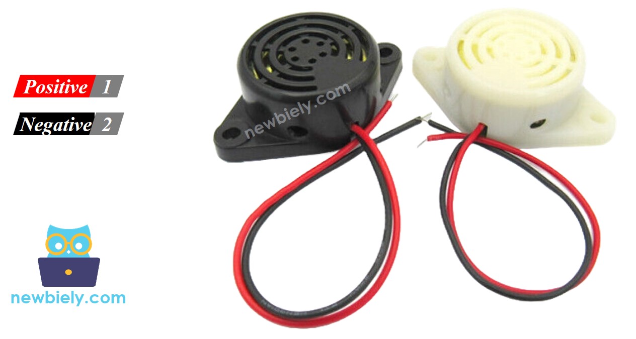
The 12V active buzzer has two clearly marked terminals:
Polarity Matters: Unlike passive buzzers, active buzzers require correct polarity. Reversing the connections can damage the internal electronics. Always double-check: red to +12V, black to GND!
How to Control 12V Active Buzzer
The Challenge: The buzzer requires 12V and substantial current (30-100mA). Arduino pins provide only 3.3V and a maximum of 15mA. Direct connection is impossible and would damage your Arduino!
The Solution: Use a relay as an electronic switch. The relay acts as a bridge:
How It Works:
The relay physically separates the low-voltage Arduino circuit from the high-voltage buzzer circuit, ensuring safety.
New to Relays? If you're unfamiliar with relay operation, pinout, and programming, start with our comprehensive Arduino MKR WiFi 1010 - Relay tutorial. Understanding relays is essential for this project!
Wiring Diagram
Carefully follow this wiring diagram. Pay special attention to the power connections—mixing up 12V and 3.3V connections can damage components!
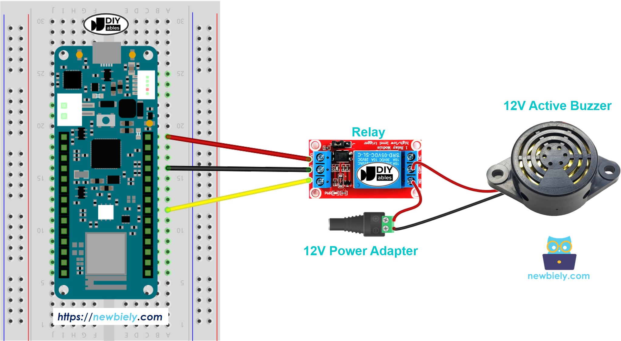
This image is created using Fritzing. Click to enlarge image
Critical Wiring Points:
Safety Reminder: Never connect the 12V supply directly to Arduino pins! The relay isolates the high-voltage buzzer circuit from the low-voltage Arduino.
Arduino MKR WiFi 1010 Code
This program creates a repeating alarm pattern: the buzzer sounds for one second, then stays silent for two seconds. This on-off pattern continues indefinitely.
Pattern: BEEP (1s) - silence (2s) - BEEP (1s) - silence (2s) - repeat...
This timing pattern is easily customizable—adjust the delay values to create different alarm patterns (rapid beeping, slow pulses, etc.).
Detailed Instructions
New to Arduino MKR WiFi 1010? Start with our Getting Started with Arduino MKR WiFi 1010 tutorial for board setup.
Follow these steps:
Safety Note: The 12V buzzer is significantly louder than phone or computer speakers. Test in an appropriate environment and protect your hearing during initial testing!
Code Explanation
The code is well-commented, but here's the logic flow:
- Send HIGH to relay (buzzer turns ON)
- Wait 1000ms (buzzer sounds for 1 second)
- Send LOW to relay (buzzer turns OFF)
- Wait 2000ms (silence for 2 seconds)
- Repeat forever
Customization Ideas: