Arduino MKR WiFi 1010 - Flame Sensor
Build fire detection and safety systems! Flame sensors detect infrared radiation from fire, enabling your Arduino MKR WiFi 1010 to respond to flames for safety alarms, automatic suppression systems, or fire monitoring. This tutorial teaches you how to connect a flame sensor to your Arduino MKR WiFi 1010 and program it to detect flames using both digital and analog readings.
What You'll Learn:
- Connecting flame sensor to Arduino MKR WiFi 1010 digital and analog pins
- Programming Arduino MKR WiFi 1010 to detect fire using flame sensor digital output
- Using Arduino MKR WiFi 1010 to measure flame intensity with flame sensor analog output
- Adjusting flame sensor sensitivity with Arduino MKR WiFi 1010 projects
- Understanding infrared flame detection with Arduino MKR WiFi 1010
- Creating fire alarm systems using Arduino MKR WiFi 1010 and flame sensors
- Implementing flame threshold detection on Arduino MKR WiFi 1010
Real-World Applications:
- Fire alarms: Use Arduino MKR WiFi 1010 with flame sensor to trigger emergency alerts
- Automatic suppression: Arduino MKR WiFi 1010 flame sensor activating fire extinguisher systems
- Kitchen safety: Arduino MKR WiFi 1010 and flame sensor monitoring stove flames
- Industrial monitoring: Arduino MKR WiFi 1010 with flame sensors detecting furnace fires
- Robot fire-fighting: Arduino MKR WiFi 1010 flame sensor guiding autonomous firefighting robots
- Camp safety: Arduino MKR WiFi 1010 and flame sensor monitoring campfire status
- Laboratory safety: Arduino MKR WiFi 1010 flame sensor detecting Bunsen burner flames
- Home automation: Arduino MKR WiFi 1010 with flame sensors for candle monitoring
Safety Applications:
You can extend this Arduino MKR WiFi 1010 flame sensor project by adding buzzers or relays to create automated fire response systems that alert people or activate suppression equipment when flames are detected.
Hardware Preparation
| 1 | × | Arduino MKR WiFi 1010 | |
| 1 | × | Micro USB Cable | |
| 1 | × | Flame Sensor | |
| 1 | × | 5-in-1 5-way Flame Sensor | |
| 1 | × | Breadboard | |
| 1 | × | Jumper Wires |
Or you can buy the following kits:
| 1 | × | DIYables Sensor Kit (18 sensors/displays) |
Additionally, some of these links are for products from our own brand, DIYables .
Overview of Flame Sensor
What is a Flame Sensor?
A flame sensor (also called infrared flame sensor, fire sensor, or IR flame detector) is a sensor designed to detect the presence of fire by sensing the infrared radiation emitted by flames.
How Flame Sensors Work:
- Flames emit infrared (IR) radiation in the wavelength range of 760-1100nm
- Flame sensors contain IR photodiodes or phototransistors sensitive to this range
- The sensor detects IR radiation and converts it to electrical signals
- Built-in comparator converts analog signal to digital output
Why Use Flame Sensors?
- Fast response: Detects flames instantly (faster than smoke detectors)
- Direct fire detection: Responds to actual flames, not just heat or smoke
- Dual outputs: Provides both digital (detected/not detected) and analog (intensity) signals
- Adjustable sensitivity: Built-in potentiometer allows threshold adjustment
- Wide detection angle: Typically 60-degree cone of detection
- Cost-effective: Inexpensive solution for fire detection projects
Important Limitations:
- False positives possible: Can be triggered by sunlight, hot objects, or other IR sources
- False negatives possible: May miss fires if flames are blocked or outside detection range
- Line-of-sight required: Cannot detect fire through walls or obstacles
- Limited range: Effective detection typically 0.8-1.5 meters
- Not a safety device: Suitable for projects but not certified for life-safety applications
Common Applications:
- Fire alarm and detection systems
- Automatic fire suppression triggers
- Robot fire-fighting competitions
- Industrial furnace monitoring
- Stove and burner flame monitoring
- Laboratory safety systems
- Educational fire detection projects
Flame Sensor Outputs
Flame sensors provide two types of outputs that can be used independently or together:
1. Digital Output (DO Pin):
- Simple fire detection: HIGH when no flame, LOW when flame detected
- Adjustable threshold: Use built-in potentiometer to set sensitivity
- LED indicator: Built-in LED shows detection status
- Perfect for: Alarms, binary detection, triggering actions
2. Analog Output (AO Pin):
- Flame intensity measurement: Value increases with stronger IR radiation
- Variable readings: Typically 0-1023 range on Arduino
- Distance sensing: Higher values when closer to flame
- Perfect for: Measuring flame strength, distance estimation, gradual responses
Pinout
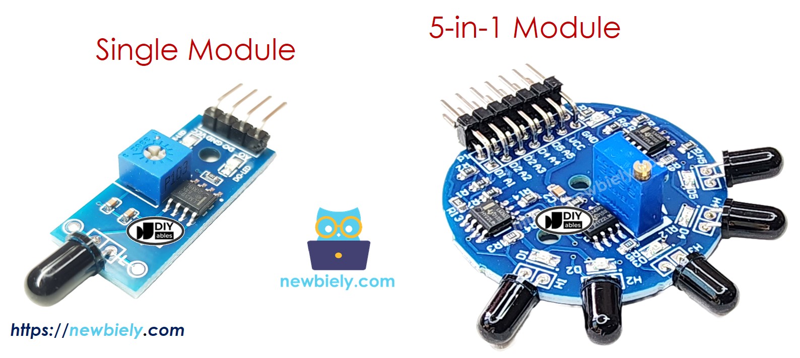
Flame sensors come in two common configurations:
Available Modules:
- Single Flame Sensor Module: One directional sensor
- 5-in-1 5-way Detection Flame Sensor Module: Five sensors in different directions
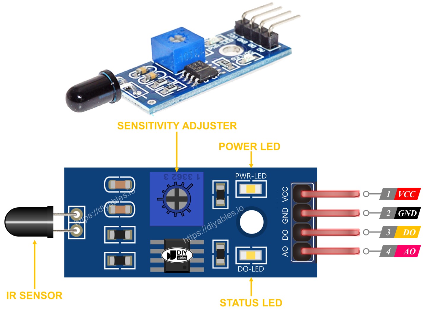
Single Flame Sensor Pinout
A standard single flame sensor module has four pins:
Power Pins:
- VCC pin: Connect to power supply (3.3V or 5V)
- 5V recommended for best performance
- Module includes voltage regulator
- GND pin: Connect to ground (0V)
- Common ground with Arduino
- DO pin (Digital Output): Digital flame detection signal
- HIGH: No flame detected (pulled up internally)
- LOW: Flame detected (above threshold)
- Threshold adjustable via potentiometer
- Can connect directly to Arduino digital input
- AO pin (Analog Output): Analog IR intensity signal
- Higher values: Stronger IR radiation (closer/bigger flame)
- Lower values: Weaker IR radiation (farther/smaller flame)
- Range: 0-1023 on Arduino (10-bit ADC)
- Not affected by potentiometer adjustment
- Power LED (usually red):
- Lights up when module is powered
- Indicates module is receiving power
- Always on when VCC connected
- Status LED (usually green/blue):
- Connected to DO pin
- Lights up when flame detected (DO goes LOW)
- Visual confirmation of detection
- Helps during sensitivity adjustment
- Small blue or white adjustment screw on module
- Turn clockwise: Decrease sensitivity (requires stronger/closer flame)
- Turn counterclockwise: Increase sensitivity (detects weaker/farther flames)
- Affects DO pin threshold only (AO pin unaffected)
- Test and adjust while pointing at flame
- One potentiometer controls all five sensors
- Common VCC and GND connections
- Power LED indicator
- Separate DO pin (5 total)
- Separate AO pin (5 total)
- Each sensor faces different direction
- Independent detection for each angle
- 360-degree coverage (when mounted properly)
- Redundancy - multiple sensors reduce false negatives
- Directional fire localization
- Perfect for robot fire-fighting applications
- Flame sensor continuously measures IR radiation
- Converts IR intensity to analog voltage
- Compares voltage against threshold set by potentiometer
- Outputs digital signal based on comparison
- Power on the module
- Point sensor at target flame (at desired detection distance)
- Adjust potentiometer while watching status LED:
- Test at various distances and flame sizes
- Fine-tune until detection range matches requirements
- Potentiometer adjustment only affects DO pin
- AO pin remains unaffected by potentiometer
- Over-sensitivity causes false positives (sunlight, heat sources)
- Under-sensitivity causes missed detections
- High IR radiation (strong/close flame) → High analog value (close to 1023)
- Low IR radiation (weak/far flame) → Low analog value (close to 0)
- No flame → Low baseline value (typically 50-200)
- Distance estimation: Approximate distance to flame
- Flame strength: Measure fire intensity
- Gradual response: Adjust fan speed based on flame proximity
- Multiple thresholds: Different actions for different intensities
- Data logging: Record flame intensity over time
Output Pins:
LED Indicators:
Most flame sensor modules include two LEDs:
Potentiometer (Sensitivity Adjustment):
5-in-1 Flame Sensor Configuration
The 5-in-1 module combines five flame sensors on one board:
Shared Components:
Individual Components (per sensor):
Advantages:
How It Works
Digital Output (DO Pin) Operation
The digital output provides simple YES/NO flame detection:
Internal Comparator Circuit:
Detection States:
Sensitivity Adjustment Process:
- Turn clockwise if LED doesn't light (increase threshold - less sensitive)
- Turn counterclockwise if LED lights too easily (decrease threshold - more sensitive)
Important Notes:
Analog Output (AO Pin) Operation
The analog output provides flame intensity measurement:
Behavior:
Typical Value Ranges:
Use Cases for Analog Output:
Key Insight:
The potentiometer does not affect the AO pin. If you need adjustable analog thresholds, implement them in your Arduino code, not via the potentiometer.
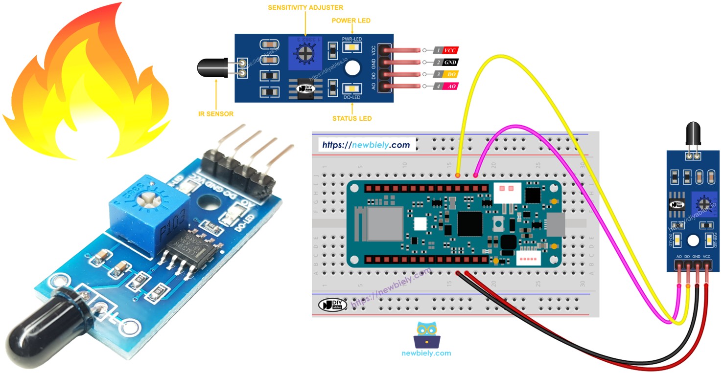
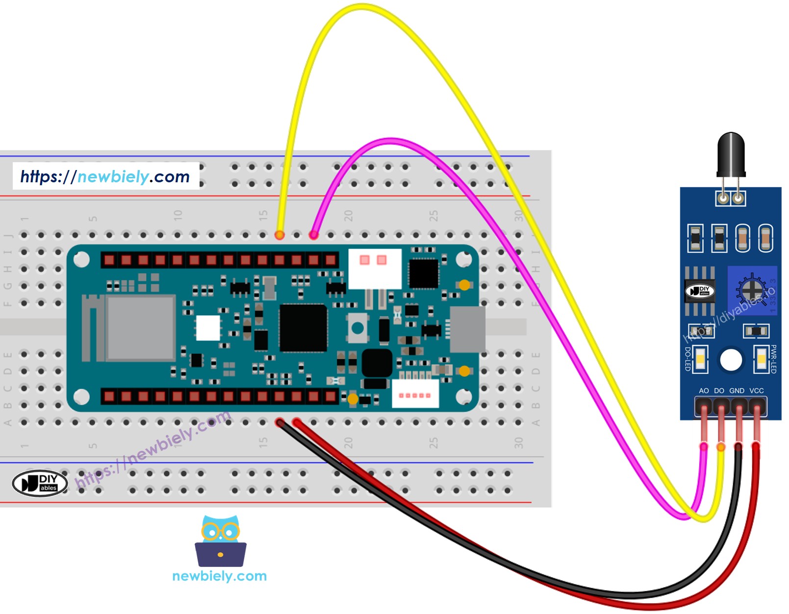
Wiring Diagram
The flame sensor module provides two outputs (DO and AO). You can use either one or both depending on your project requirements.
This configuration uses both DO and AO pins for complete flame detection and intensity measurement:
This image is created using Fritzing. Click to enlarge image
Connections:
- Flame Sensor VCC → Arduino 5V
- Provides power to sensor module
- 5V recommended for optimal performance
- Flame Sensor GND → Arduino GND
- Common ground connection
- Flame Sensor DO → Arduino D2 (digital input)
- Digital flame detection signal
- Configure as INPUT in code
- Flame Sensor AO → Arduino A0 (analog input)
- Analog flame intensity signal
- Read with analogRead() function
- Simple fire alarm (detected/not detected)
- Triggering relay or buzzer
- Binary fire detection
- Fewer Arduino pins needed
- Measuring flame intensity
- Distance-based responses
- Gradual flame strength monitoring
- Custom threshold in software
- Need both detection confirmation and intensity measurement
- Want to compare digital threshold with analog value
- Testing and calibration purposes
- Advanced fire detection algorithms
- Sensor orientation: Point IR detector toward expected flame location
- Mounting: Use stable mount to prevent vibration affecting readings
- Distance: Keep wires short (under 50cm) to minimize noise
- Testing: Test with real flame (candle, lighter) during setup
- Safety: Never leave flame unattended during testing
When to Use Digital Only:
When to Use Analog Only:
When to Use Both Outputs:
Wiring Tips:
Power Supply:
For This Project: Simply plug your Arduino MKR WiFi 1010 into your computer's USB port. The flame sensor module draws minimal current (<50mA), well within USB power limits.
Arduino MKR WiFi 1010 Code - Read Value from DO Pin
This first example uses the digital output for simple flame detection. Perfect for fire alarms, automated suppression triggers, or any application requiring YES/NO flame detection.
What the Code Does:
- Configures digital pin D2 as input for flame sensor DO pin
- Continuously reads digital state (HIGH = no flame, LOW = flame detected)
- Displays clear "DETECTED" or "NOT DETECTED" messages
- Updates readings every 500ms for real-time monitoring
- Simple binary detection - no analog complexity
Code Explanation - Digital Detection
Pin Configuration:
Configures D2 as digital input. No pull-up needed - flame sensor has active output driver.
Reading Digital State:
Reads current DO pin state:
- LOW: Flame detected (IR level above threshold)
- HIGH: No flame detected (IR level below threshold)
Interpreting Results:
Important: LOW means detected (inverse logic due to sensor design).
Practical Applications:
1. Fire Alarm:
2. Automatic Suppression:
3. Safety Cutoff:
Detailed Instructions
New to Arduino MKR WiFi 1010? Complete our Getting Started with Arduino MKR WiFi 1010 tutorial first to set up your development environment.
Step 1: Hardware Setup
- Connect flame sensor to Arduino MKR WiFi 1010 following wiring diagram:
- VCC to 5V
- GND to GND
- DO to D2
- Mount sensor pointing toward test area
Step 2: Connect and Configure
- Use USB cable to connect Arduino MKR WiFi 1010 to your computer
- Launch Arduino IDE
- Select Arduino MKR WiFi 1010 board and COM port
Step 3: Upload Code
- Copy the code above
- Open in Arduino IDE
- Click Upload button
- Wait for "Done uploading" message
Step 4: Adjust Sensitivity
- Open Serial Monitor (baud rate: 9600)
- Light a candle or use lighter
- Place flame about 30-50cm from sensor
- Observe Serial Monitor:
- If flame not detected, turn potentiometer counterclockwise (increase sensitivity)
- If false positives occur, turn potentiometer clockwise (decrease sensitivity)
- Find optimal setting where flame reliably detected at desired distance
Step 5: Test Flame Detection
- Point sensor at flame - should see "DETECTED" messages
- Remove flame - should see "NOT DETECTED" messages
- Watch status LED on sensor module (lights when flame detected)
- Test at various distances to verify detection range
Expected Serial Monitor Output:
Sensitivity Adjustment Tips:
- LED stays on constantly: Too sensitive - turn clockwise
- LED never lights: Not sensitive enough - turn counterclockwise
- Intermittent false triggers: Reduce sensitivity or shield from sunlight
- Optimal setting: Detects flame at desired distance without false positives
Arduino MKR WiFi 1010 Code - Read Value from AO Pin
This second example uses the analog output to measure flame intensity. Perfect for distance estimation, gradual responses, or analyzing flame characteristics.
What the Code Does:
- Configures analog pin A0 as input for flame sensor AO pin
- Continuously reads analog value (0-1023 range)
- Displays raw analog readings for analysis
- Higher values indicate stronger IR radiation (closer/bigger flame)
- Updates readings every 200ms for smooth data flow
- Potentiometer adjustment does NOT affect these readings
Code Explanation - Analog Intensity Measurement
Reading Analog Value:
Reads 10-bit ADC value (0-1023):
- Low values (0-200): No flame or very distant
- Medium values (200-600): Flame detected at moderate distance
- High values (600-1023): Strong flame or very close
Understanding the Values:
Practical Applications:
1. Distance-Based Response:
2. Variable Fan Speed:
3. Fire-Fighting Robot:
4. Data Logging:
Detailed Instructions
New to Arduino MKR WiFi 1010? Complete our Getting Started with Arduino MKR WiFi 1010 tutorial first to set up your development environment.
Step 1: Hardware Setup
- Connect flame sensor to Arduino MKR WiFi 1010:
- VCC to 5V
- GND to GND
- AO to A0 (analog input)
- Position sensor pointing toward test area
Step 2: Upload and Test
- Copy the code above into Arduino IDE
- Select Arduino MKR WiFi 1010 board and COM port
- Click Upload button
- Open Serial Monitor (baud rate: 9600)
Step 3: Observe Analog Values
- With no flame, note baseline value (typically 50-200)
- Light a candle
- Slowly move flame closer to sensor
- Watch values increase as flame gets closer
- Move flame away and watch values decrease
Expected Serial Monitor Output:
Understanding Your Readings:
- Low consistent values (50-200): No flame present
- Sudden increase (300+): Flame entering detection range
- High values (700-1000): Flame very close
- Gradual decrease: Flame moving away
- Fluctuating values: Normal - flames are dynamic
Calibration Tips:
- Note maximum value at desired detection distance
- Set software threshold slightly below maximum
- Test with different flame sizes (candle vs lighter)
- Account for ambient IR sources (sunlight)
- Remember: Potentiometer does NOT affect analog readings
Troubleshooting Common Issues
Problem: Sensor Always Detects Flame (DO LED Always On)
Possible Causes:
- Potentiometer set too sensitive
- Strong ambient IR sources (sunlight, hot objects)
- Sensor pointing at heat source
- Faulty sensor module
Solutions:
- Turn potentiometer clockwise to decrease sensitivity
- Shield sensor from direct sunlight
- Point sensor away from hot surfaces (computers, lamps)
- Test in controlled lighting conditions
- Verify sensor in dark room first
Problem: Sensor Never Detects Flame
Possible Causes:
- Potentiometer set not sensitive enough
- Flame outside detection range (>1.5m)
- Sensor not pointed at flame
- Wiring error
- Dead sensor
Solutions:
- Turn potentiometer counterclockwise to increase sensitivity
- Move sensor closer to flame (30-50cm)
- Check sensor orientation - IR detector faces flame
- Verify wiring: VCC to 5V, GND to GND, DO to D2
- Test DO pin voltage with multimeter
- Try different flame sensor module
Problem: Analog Values Always Read Low (~50-150)
Possible Causes:
- AO pin not connected properly
- Wrong pin in code
- Sensor not powered
- Faulty AO circuit
Solutions:
- Verify AO pin connected to A0 on Arduino
- Check code: analogRead(A0) matches your wiring
- Confirm VCC and GND connected
- Test sensor with known-good flame (candle)
- Try different analog pin and update code
Problem: Erratic or Noisy Readings
Possible Causes:
- Electrical interference
- Long or poor quality wires
- Unstable power supply
- Ambient IR fluctuations
Solutions:
- Use shorter wires (<30cm) between sensor and Arduino
- Add 100μF capacitor between VCC and GND (near sensor)
- Average multiple readings in code:
- Shield wires from motors and power lines
- Use filtered power supply
Problem: False Positives from Sunlight
Cause: Sunlight contains IR radiation that triggers sensor.
Solutions:
- Shield sensor from direct sunlight
- Reduce sensitivity with potentiometer
- Mount sensor indoors away from windows
- Add IR filter in front of sensor (flame wavelengths only)
- Use dual confirmation (multiple sensors)
Problem: DO and AO Give Conflicting Results
Cause: Potentiometer threshold doesn't match your analog threshold in code.
Solution: Remember that potentiometer only affects DO pin. Set thresholds independently:
- DO threshold: Adjust with potentiometer
- AO threshold: Set in code based on observed values
Challenge Yourself - Creative Extensions
Once you have the basic flame sensor working, try these enhancements:
1. Complete Fire Alarm System
Combine flame sensor with buzzer and LED:
2. WiFi Fire Alert Notifications
Send alerts to your phone using Arduino MKR WiFi 1010's WiFi:
3. Automatic Fire Suppression
Activate water pump or CO2 system:
4. Multi-Zone Fire Detection
Monitor multiple rooms with multiple sensors:
5. Fire-Fighting Robot
Create autonomous fire-fighting robot:
6. LCD Fire Status Display
Show detection status on LCD:
7. Temperature-Compensated Detection
Combine with temperature sensor for better accuracy:
8. Data Logging to SD Card
Log all flame events with timestamps:
9. Safety Interlock System
Prevent false activations with confirmation delay:
10. Integration with Home Automation
Control home systems based on fire detection:
Experiment and learn - but always prioritize safety!