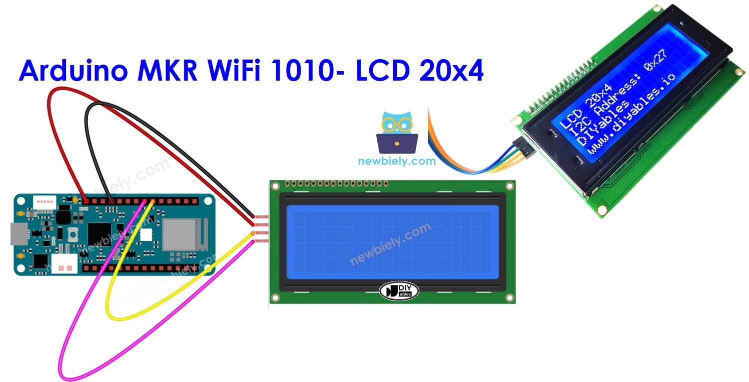
Arduino MKR WiFi 1010 - LCD 20x4
The 20x4 LCD display is one of the most versatile and information-rich output devices you can connect to your Arduino MKR WiFi 1010. With 80 characters of display space (20 columns × 4 rows), this LCD provides significantly more room than the standard 16x2 display, making it perfect for creating comprehensive status dashboards, multi-line menus, data logging displays, and complex user interfaces with your Arduino MKR WiFi 1010.
This comprehensive Arduino MKR WiFi 1010 LCD 20x4 tutorial teaches you everything you need to display text, numbers, and custom characters on a large 20x4 LCD screen using the I2C communication protocol. The I2C interface means you only need 2 pins (SDA and SCL) on your Arduino MKR WiFi 1010 regardless of LCD size, leaving plenty of GPIO pins free for sensors, buttons, and other components. The Arduino MKR WiFi 1010's built-in WiFi capability combined with a 20x4 LCD lets you create IoT devices that display real-time data from the internet, weather information, social media notifications, or system status across four informative lines.
In this tutorial, you'll learn how to wire a 20x4 I2C LCD to your Arduino MKR WiFi 1010, find and configure the correct I2C address, understand the LCD coordinate system for precise text placement, use the DIYables_LCD_I2C library to control the display, position text on any of the 80 character locations, create multi-line displays with properly aligned information, and build practical projects that take advantage of the 20x4 LCD's spacious display area. The Arduino MKR WiFi 1010's powerful processor handles LCD updates smoothly even when displaying dynamic content across all four rows.
Whether you're building a WiFi-connected weather station that shows temperature, humidity, pressure, and forecast on separate lines, creating an IoT device dashboard that monitors multiple sensors with labeled readings, designing a menu-driven control system for home automation, or developing a data logger that displays timestamps and multiple sensor values simultaneously, the 20x4 LCD with your Arduino MKR WiFi 1010 provides the perfect display solution for information-rich applications.
Hardware Preparation
| 1 | × | Arduino MKR WiFi 1010 | |
| 1 | × | Micro USB Cable | |
| 1 | × | LCD 20x4 | |
| 1 | × | Jumper Wires | |
| 1 | × | Optionally, DC Power Jack |
Or you can buy the following kits:
| 1 | × | DIYables Sensor Kit (18 sensors/displays) |
Additionally, some of these links are for products from our own brand, DIYables .
Buy Note: Alternatively, you can assemble the LCD I2C display using LCD 1602 Display and PCF8574 I2C Adapter Module.
Overview of LCD I2C 20x4
Why Choose a 20x4 LCD?
The 20x4 LCD display offers 80 character positions (20 columns × 4 rows), providing 2.5 times more display space than the standard 16x2 LCD (which has only 32 characters). This extra space is invaluable for applications that need to display multiple pieces of information simultaneously:
More Information at a Glance: Display sensor readings with labels, status indicators, timestamps, and instructions all on one screen without scrolling or switching screens. For example, a weather station can show "Temp: 25.3C", "Humidity: 65%", "Pressure: 1013mb", and "Status: Normal" all at once.
Better Organization: Four rows let you create clear visual hierarchy - use the first row for titles/headers, middle rows for data, and the last row for status messages or instructions. This creates professional-looking interfaces that users can understand at a glance.
Multi-Parameter Monitoring: Perfect for projects monitoring multiple sensors or system parameters. Display temperature, humidity, light levels, motion status, WiFi connection state, and more - all visible simultaneously without cycling through screens.
Complex Menus: Create sophisticated menu systems with multiple visible options. Users can see more menu items at once (up to 4), making navigation more intuitive than single-line displays that require more scrolling.
20x4 vs 16x2 LCD Comparison
| Feature | 16x2 LCD | 20x4 LCD | Advantage |
|---|---|---|---|
| Display Size | 16 columns × 2 rows | 20 columns × 4 rows | 20x4 has 2.5x more space |
| Total Characters | 32 characters | 80 characters | 20x4 shows much more data |
| Physical Size | Typically 80mm × 36mm | Typically 98mm × 60mm | 20x4 is larger but not bulky |
| I2C Pins Required | 4 pins (VCC, GND, SDA, SCL) | 4 pins (VCC, GND, SDA, SCL) | Same - no extra pins needed |
| Power Consumption | ~25mA (backlight off) | ~35mA (backlight off) | Similar power usage |
| Current Draw | ~120mA (backlight on) | ~150mA (backlight on) | 20x4 slightly higher |
| Price | Lower cost (~$3-5) | Higher cost (~$6-10) | 16x2 more economical |
| Best For | Simple status displays, basic projects | Dashboards, data logging, complex menus | Depends on information needs |
| Arduino Memory | ~1KB RAM usage | ~1KB RAM usage | Same memory footprint |
When to Use 20x4 Instead of 16x2:
- You need to display more than 2-3 labeled values simultaneously
- Building a dashboard or monitoring system with multiple parameters
- Creating menu systems where seeing 4 options at once improves usability
- Displaying formatted tables or multi-line information
- Projects where screen real estate matters more than cost or size
- Applications showing timestamps, labels, and data together
When 16x2 is Sufficient:
- Displaying simple single-value readings (like temperature only)
- Budget-constrained projects
- Space-limited enclosures
- Single-line status messages or basic menus
- Projects for beginners learning LCD basics
How I2C Makes Large LCDs Easy
Without I2C, a 20x4 LCD would require 16 GPIO pins on your Arduino MKR WiFi 1010 (8 data pins + 3 control pins + backlight control + power/ground). The I2C backpack adapter reduces this to just 2 pins (SDA and SCL), making it practical to use large displays without running out of available GPIO pins.
The I2C protocol handles all communication serially - your Arduino MKR WiFi 1010 sends characters and commands over the SDA (data) line, synchronized by the SCL (clock) line. The I2C backpack converts these serial commands into the parallel signals the LCD needs. This means:
- No pin shortage - you still have plenty of GPIO pins for sensors, buttons, motors, etc.
- Simpler wiring - only 4 wires total (VCC, GND, SDA, SCL)
- Multiple I2C devices - you can connect other I2C devices (OLED displays, sensors, RTCs) on the same two pins
- Longer cable runs possible - I2C can work over several feet of cable with proper wiring
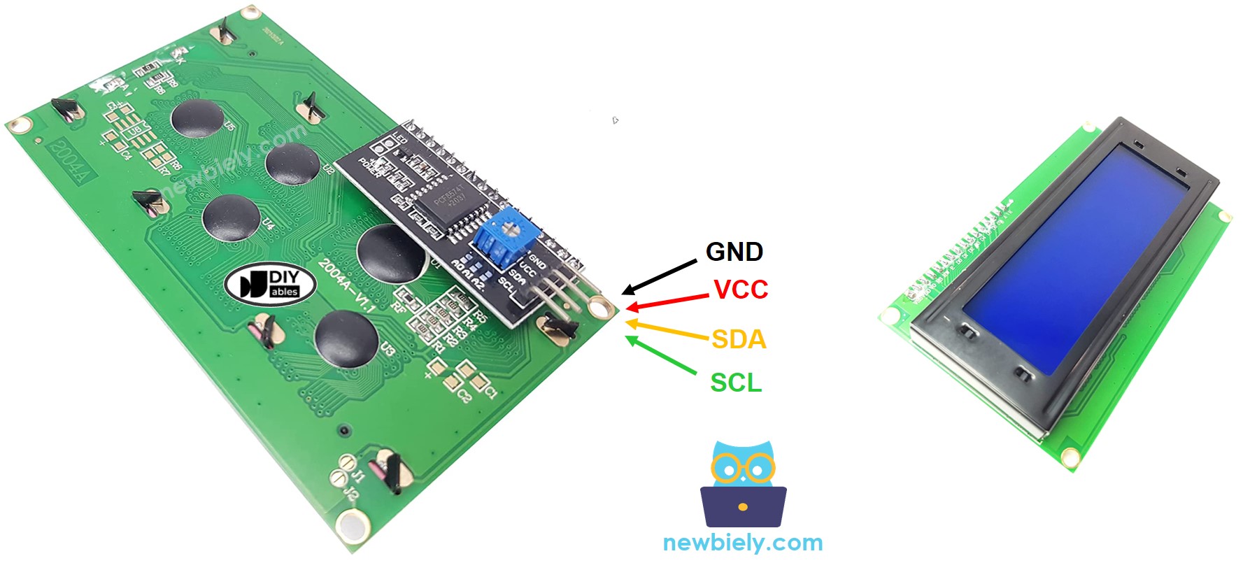
Pinout
The 20x4 LCD with I2C backpack has four pins - the same as any I2C device regardless of display size:
- GND pin: Connect this to ground (0 volts) - provides the ground reference for the LCD
- VCC pin: Connect this to the power supply (5 volts) - powers both the LCD and backlight LEDs
- SDA pin: This is the I2C data line - carries the actual character data and commands from Arduino MKR WiFi 1010
- SCL pin: This is the I2C clock line - provides timing synchronization for data transfer
Important Notes About the I2C Backpack:
- The small blue board attached to the back of your LCD is the I2C adapter (also called I2C backpack or I2C module)
- This adapter has a contrast potentiometer (small blue box with screw adjustment) - if your display shows no text or only blue rectangles, adjust this with a small screwdriver
- Most I2C backpacks use address 0x27 or 0x3F - you may need to determine yours using an I2C scanner
- The backpack should be firmly soldered to the LCD pins - loose connections cause display problems
- Some backpacks have a jumper to disable the backlight (saves power) - check documentation if your backlight won't turn on
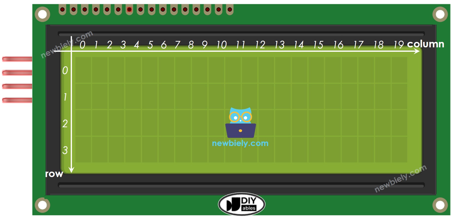
LCD Coordinate System
Understanding the LCD coordinate system is essential for positioning text exactly where you want it on the 20x4 display. The coordinate system uses two values: column (horizontal position) and row (vertical position).
Coordinate Numbering (CRITICAL - this trips up many beginners!):
- Columns are numbered 0 to 19 (not 1 to 20) - there are 20 columns total
- Rows are numbered 0 to 3 (not 1 to 4) - there are 4 rows total
- The top-left position is (column=0, row=0)
- The top-right position is (column=19, row=0)
- The bottom-left position is (column=0, row=3)
- The bottom-right position is (column=19, row=3)
Using lcd.setCursor(column, row):
Common Mistakes to Avoid:
- ❌ Wrong: lcd.setCursor(20, 4); - These coordinates are OUT OF BOUNDS (column 20 and row 4 don't exist)
- ❌ Wrong: lcd.setCursor(1, 1); thinking it's the "first position" - this is actually the second column, second row
- ✅ Correct: lcd.setCursor(0, 0); for the very first position
- ✅ Correct: Count from 0, not from 1, for both columns and rows
Practical Layout Examples:
Result on LCD:
Tips for Centering Text:
- To center text, calculate: column = (20 - text_length) / 2
- Example: "Hello" is 5 characters → column = (20-5)/2 = 7.5 → use column 7
- lcd.setCursor(7, 1); lcd.print("Hello"); centers "Hello" on row 1
Tips for Right-Aligning Text:
- To right-align, calculate: column = 20 - text_length
- Example: "99.9C" is 5 characters → column = 20-5 = 15
- lcd.setCursor(15, 0); lcd.print("99.9C"); right-aligns the temperature
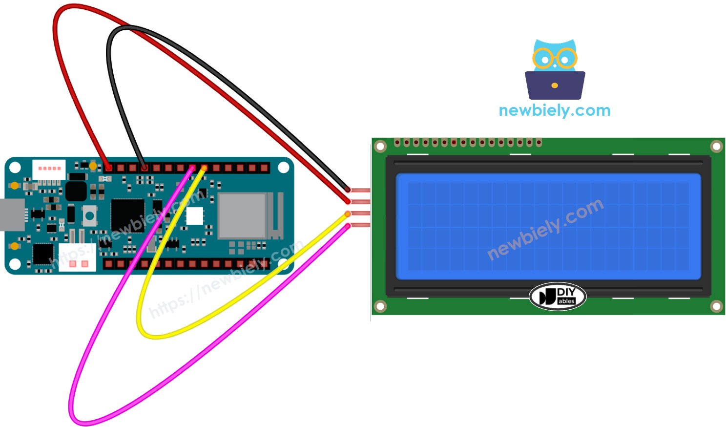
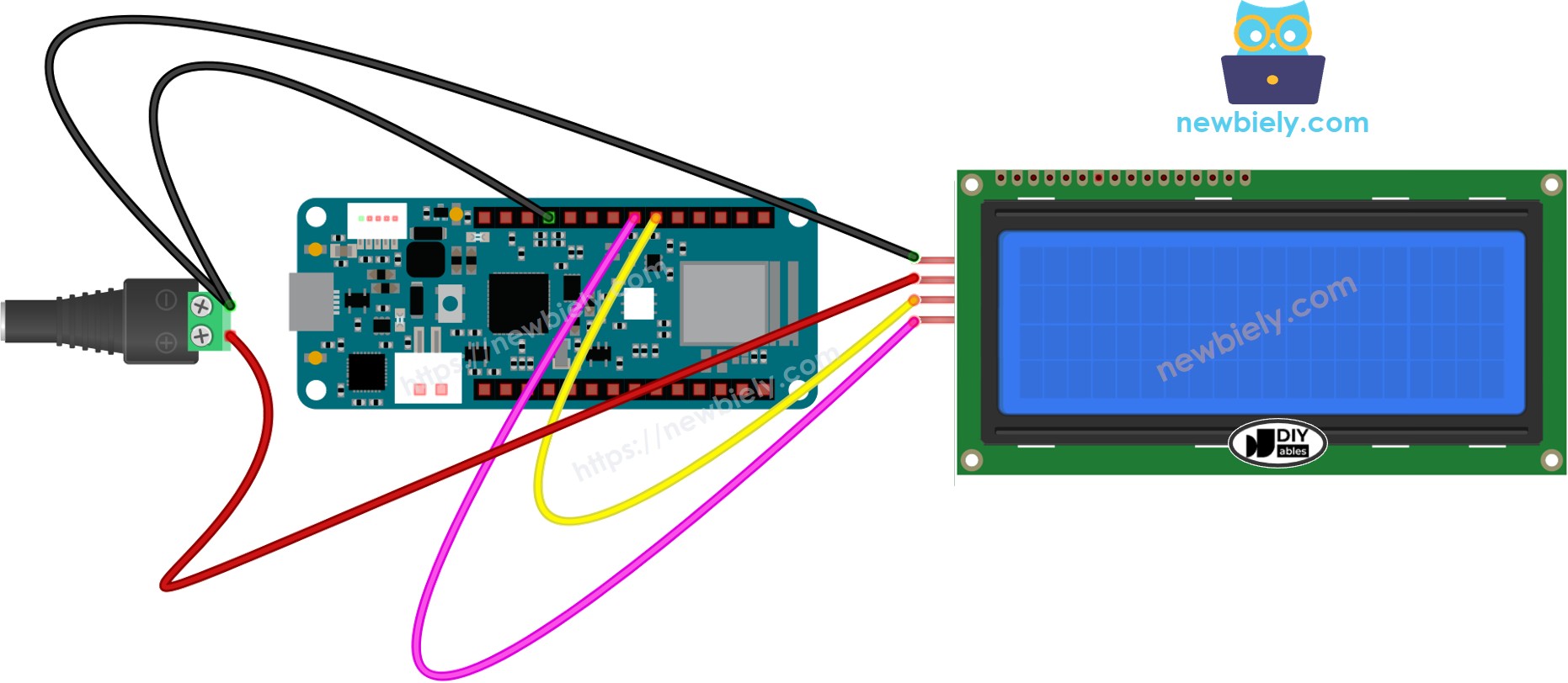
Wiring Diagram
Connecting a 20x4 LCD to your Arduino MKR WiFi 1010 is straightforward thanks to the I2C interface, but proper power connections are critical due to the larger display's higher current requirements.
Two Power Options
Option 1: USB Power Only (shown in first diagram):
- Suitable for development and testing
- Arduino MKR WiFi 1010 powered via USB from computer
- LCD gets 5V power from Arduino's 5V pin
- Limitation: USB may not provide enough current if backlight is at full brightness or if you add many other components
- Symptom of insufficient power: LCD backlight dims, display flickers, or shows corrupted characters
This image is created using Fritzing. Click to enlarge image
Option 2: External Power Supply (shown in second diagram):
- Required for permanent installations or battery-powered projects
- External 5V power supply (1A or more) connects to Arduino's Vin pin
- LCD gets stable 5V power from the external supply via Arduino
- Advantage: Stable power prevents flickering and ensures reliable operation
- Note: Ground (GND) must be common between Arduino, LCD, and external power supply
This image is created using Fritzing. Click to enlarge image
Important Power Notes
※ NOTE THAT:
USB Power Limitations: If you power the Arduino MKR WiFi 1010 using the USB port, you can use the VBUS pin to power the LCD display without needing a separate power source. However, be aware that USB power through a computer port is typically limited to 500mA, and the VBUS pin might not provide enough current for the LCD display to work correctly, especially with the backlight at full brightness.
Symptoms of Insufficient Power:
- LCD backlight is very dim or doesn't turn on
- Display shows random characters or garbled text
- Display works initially but fails after a few seconds
- Characters flicker or disappear
- Arduino resets unexpectedly when LCD is connected
Solution: Use an external 5V power supply (1A minimum, 2A recommended) connected to the Arduino's Vin pin and GND. This ensures both the Arduino MKR WiFi 1010 and the 20x4 LCD receive stable, adequate power.
Connection Table
| LCD I2C Pin | Arduino MKR WiFi 1010 Pin | Notes |
|---|---|---|
| VCC | 5V | Provides 5V power to LCD - ensure adequate current supply |
| GND | GND | Ground reference - must be common with all components |
| SDA | A4 (pin 11) | I2C data line - this pin is dedicated for I2C communication |
| SCL | A5 (pin 12) | I2C clock line - this pin is dedicated for I2C communication |
Wiring Tips:
- Use short jumper wires (under 6 inches/15cm) for I2C connections to minimize interference
- Keep I2C wires (SDA and SCL) away from high-current wires (motor connections, relays)
- If using long I2C cables (over 1 foot), add 4.7kΩ pullup resistors on SDA and SCL lines
- Double-check VCC goes to 5V (not 3.3V) - the LCD requires 5V to operate correctly
- Ensure GND connections are solid - loose ground causes random display behavior
- The Arduino MKR WiFi 1010 is 3.3V logic but tolerates 5V on I2C pins - no level shifters needed
How To Program For LCD I2C
Programming the 20x4 LCD with your Arduino MKR WiFi 1010 is straightforward using the DIYables_LCD_I2C library. This library handles all the complex I2C communication, letting you focus on what to display rather than how to communicate with the LCD.
Step 1: Include the Library
First, include the DIYables_LCD_I2C library at the top of your sketch:
This library provides all the functions you need to control the LCD: initializing, printing text, positioning the cursor, clearing the screen, and more.
Step 2: Create LCD Object
Create a DIYables_LCD_I2C object by specifying three parameters: I2C address, number of columns, and number of rows:
Understanding the Parameters:
- First parameter (0x27): This is the I2C address of your LCD module. Common addresses are:
- 0x27 - Most common, used by DIYables, DFRobot, and many generic modules
- 0x3F - Alternative address used by some manufacturers
- If unsure, use an I2C scanner sketch to detect the correct address
- Second parameter (20): Number of columns - this is always 20 for a 20x4 LCD
- Third parameter (4): Number of rows - this is always 4 for a 20x4 LCD
Important: If your LCD doesn't work, the I2C address is the most common issue. Try changing 0x27 to 0x3F or vice versa.
Step 3: Initialize the LCD
In your setup() function, initialize the LCD hardware and turn on the backlight:
What These Functions Do:
- lcd.init() - Initializes the I2C communication, configures the LCD controller chip, clears the display, and prepares it for text
- lcd.backlight() - Turns on the LED backlight (white or blue LEDs behind the LCD) so you can see the characters. Without this, the display would be too dark to read
- Optional: Use lcd.noBacklight() if you want to turn off the backlight (saves power)
Step 4: Position the Cursor
Before printing text, move the cursor to the desired position using column and row coordinates (both start from 0):
Examples:
Important: Always call setCursor() before print() to ensure text appears where you intend. If you don't set the cursor, text continues from wherever the cursor was last positioned.
Step 5: Display Text
After positioning the cursor, print text, numbers, or variables to the LCD:
What You Can Print:
- Strings: lcd.print("Temperature");
- Numbers: lcd.print(25); or lcd.print(25.3);
- Variables: lcd.print(temperature); or lcd.print(sensorValue);
- Formatted text: lcd.print("Temp: "); lcd.print(temp); lcd.print("C");
Advanced Printing:
Additional Useful Functions
Clear the entire display:
Note: clear() is slow (takes ~2ms) - don't call it repeatedly in loop() or display will flicker. Instead, overwrite text with spaces or only clear when necessary.
Control the cursor display:
Control display on/off:
Scroll text:
Common Programming Pattern
A typical LCD program follows this pattern:
※ NOTE THAT:
Critical I2C Address Note: The LCD's I2C address might be different depending on who manufactured it. In our code examples, we use address 0x27, which is recommended by the DIYables manufacturer and is the most common. However, if your LCD doesn't display anything:
- Try changing the address to 0x3F: DIYables_LCD_I2C lcd(0x3F, 20, 4);
- Or use an I2C scanner sketch to detect your LCD's actual address
- Some rare LCDs use other addresses like 0x20 or 0x38 - scanning will find them
Arduino MKR WiFi 1010 Code
Detailed Instructions
New to Arduino MKR WiFi 1010? Complete our Getting Started with Arduino MKR WiFi 1010 tutorial first to set up your development environment.
Step 1: Check Your Hardware
- Verify you have a 20x4 LCD (not 16x2) - count the rows: there should be 4 visible rows
- Confirm the I2C backpack is attached to the back of the LCD (small blue/green PCB with 4 pins)
- Locate the contrast adjustment potentiometer (small blue box with screw slot) on the I2C backpack - you'll need this if text doesn't appear
- Check that your Arduino MKR WiFi 1010 is genuine - look for the official Arduino branding
Step 2: Wire the Components Carefully
- Connect LCD VCC to Arduino 5V pin (NOT 3.3V - the LCD requires 5V to function)
- Connect LCD GND to Arduino GND pin
- Connect LCD SDA to Arduino A4 pin (pin 11 on MKR WiFi 1010)
- Connect LCD SCL to Arduino A5 pin (pin 12 on MKR WiFi 1010)
- Double-check all connections match the wiring diagram exactly - reversed power can damage the LCD
- If using external power supply, connect supply GND to Arduino GND (common ground is essential)
Step 3: Connect Arduino to Computer
- Plug the Micro USB cable into your Arduino MKR WiFi 1010
- Connect the other end to your computer's USB port
- Wait for Windows to recognize the device (you may hear a connection sound)
- The green power LED on the Arduino should illuminate, and the LCD backlight should turn on (may be very dim without code)
Step 4: Configure Arduino IDE
- Open Arduino IDE on your computer
- Go to Tools → Board and select Arduino MKR WiFi 1010
- Go to Tools → Port and select the COM port with "Arduino MKR WiFi 1010" label
- If you don't see the port, try a different USB cable or port - some cables are power-only and can't transfer data
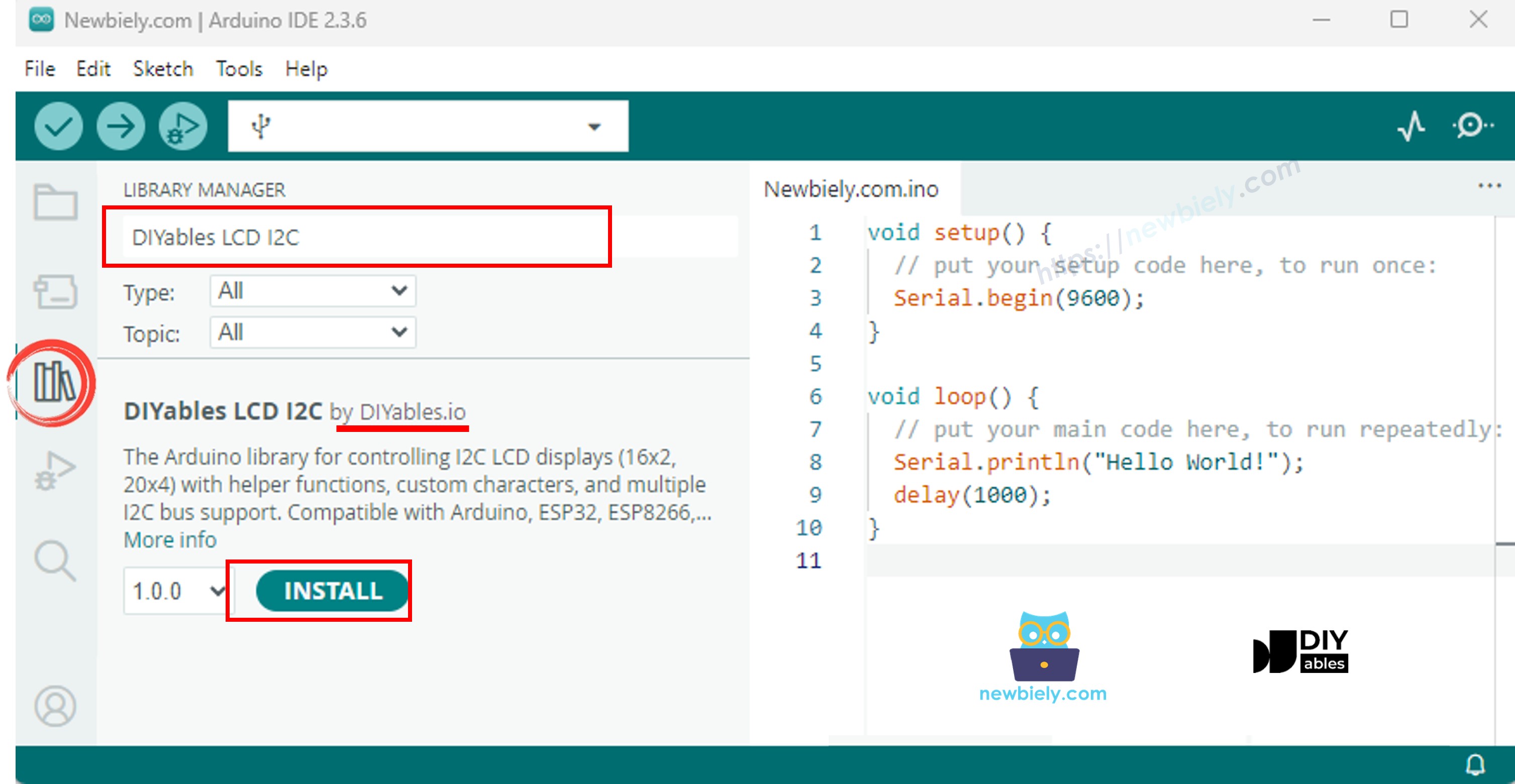
Step 5: Install Required Library
- Click the Library Manager icon (book icon) on the left sidebar of Arduino IDE
- Type DIYables LCD I2C into the search box at the top
- Look for DIYables_LCD_I2C by DIYables in the results (this is the correct library - there are several with similar names)
- Click the Install button next to it
- Wait for "INSTALLED" to appear, then close the Library Manager
Step 6: Upload and Test the Code
- Copy the complete code from the "Arduino MKR WiFi 1010 Code" section above
- Paste it into a new Arduino IDE sketch window (replace any existing code)
- Verify the LCD I2C address in the code is 0x27: DIYables_LCD_I2C lcd(0x27, 20, 4);
- Check the LCD dimensions are correct: 20, 4 means 20 columns and 4 rows
- Click the Upload button (right arrow icon) in Arduino IDE
- Wait for "Done uploading" message to appear
Step 7: Verify Display and Troubleshoot
- Look at your LCD screen - you should see text on all 4 rows:
- Row 0: "LCD 20x4"
- Row 1: "I2C Address: 0x27"
- Row 2: "DIYables"
- Row 3: "www.diyables.io"
- If backlight is on but you see no text or only blue rectangles: Use a small flathead screwdriver to gently turn the contrast potentiometer on the I2C backpack. Turn it clockwise or counterclockwise until text becomes visible - this is the most common issue!
- If nothing appears at all: The I2C address might be wrong. Change 0x27 to 0x3F in the code: DIYables_LCD_I2C lcd(0x3F, 20, 4); and upload again
- If successful: Try modifying the text in the code and uploading again to see your changes appear
- Experiment with lcd.setCursor(column, row) to position text at different locations on the 4 rows
Troubleshooting
Problem 1: LCD Backlight On But No Text Visible
Symptoms: The LCD backlight is illuminated (blue or white glow), but no characters appear, or you see only blue rectangles on all positions.
Causes:
- Contrast potentiometer incorrectly adjusted (most common issue - happens with almost all new LCDs)
- Wrong I2C address in code (0x27 vs 0x3F)
- Incorrect LCD dimensions specified in code
Solutions:
- Adjust contrast first (fixes 90% of cases): Locate the small blue potentiometer on the I2C backpack (small box with Phillips screw slot). Using a small flathead or Phillips screwdriver, gently turn it clockwise about 1/4 turn while watching the LCD. If nothing appears, turn counterclockwise instead. Continue adjusting until text becomes clearly visible. Don't force it - potentiometers have limited rotation
- Try alternate I2C address: Change your code from DIYables_LCD_I2C lcd(0x27, 20, 4); to DIYables_LCD_I2C lcd(0x3F, 20, 4); and upload. Some manufacturers use 0x3F instead of 0x27
- Verify LCD dimensions: Ensure your code specifies the correct size: lcd(address, 20, 4) - not lcd(address, 16, 2). Wrong dimensions cause display errors
- Run I2C scanner: Upload an I2C scanner sketch to detect the actual address of your LCD, then use that exact address in your code
Problem 2: LCD Completely Blank (No Backlight)
Symptoms: The LCD screen is completely dark with no backlight illumination. Nothing is visible even in bright light.
Causes:
- No power reaching the LCD (wiring error)
- Insufficient power supply
- Backlight jumper removed or backlight disabled in code
- Defective LCD or I2C backpack
Solutions:
- Check power connections carefully: Verify VCC is connected to Arduino's 5V pin (NOT 3.3V). Verify GND is connected to Arduino's GND. Use a multimeter to measure voltage at LCD's VCC pin - should read 4.5-5.5V
- Test with external power: If powered via USB, try an external 5V power supply (1A minimum) connected to Arduino's Vin pin. USB might not provide enough current
- Check for backlight disable jumper: Some I2C backpacks have a jumper (small connector that can be removed) to disable the backlight. Look for a 2-pin header labeled "BL" or "LED" - ensure the jumper is in place
- Verify backlight() command: Ensure your code includes lcd.backlight(); in setup(). Try adding lcd.noBacklight(); delay(1000); lcd.backlight(); to toggle it
- Test I2C communication: If the Arduino Serial Monitor shows errors like "LCD not found at address 0x27", the I2C backpack may be defective or not soldered properly
Problem 3: Garbled Characters or Random Symbols
Symptoms: LCD displays random characters, symbols, or scrambled text instead of your intended message. Characters may change randomly or flicker.
Causes:
- I2C communication errors (loose wires, interference)
- Insufficient power causing voltage drops
- I2C clock speed too high for long wires
- Ground connection problems
Solutions:
- Check I2C wire connections: Firmly press all jumper wires into place. Try replacing SDA and SCL wires with fresh ones - intermittent connections cause garbled display
- Ensure solid ground connection: Connect an additional GND wire between Arduino and LCD GND pins. Poor ground is a common cause of display corruption
- Add power filtering capacitor: Solder a 100µF electrolytic capacitor across the LCD's VCC and GND pins (observe polarity: negative stripe to GND). This stabilizes power and reduces display errors
- Reduce I2C speed for long wires: If using wires longer than 1 foot, add this line before lcd.init() in setup: Wire.setClock(50000); (reduces I2C speed from default 100kHz to 50kHz)
- Use external power supply: USB power may have noise or insufficient current. Switch to a dedicated 5V 1-2A power supply
- Shorten wire length: Keep I2C wires (SDA and SCL) under 6 inches (15cm) if possible. Long wires pick up interference
Problem 4: Text Appears in Wrong Position
Symptoms: Text appears but not where you expected it. Characters may be cut off, overlap, or appear on the wrong row.
Causes:
- Incorrect coordinate calculations (forgetting 0-indexing)
- Wrong LCD dimensions in code
- Cursor not positioned before printing
- Text longer than row width
Solutions:
- Remember 0-indexing: Columns are 0-19 (not 1-20) and rows are 0-3 (not 1-4). The first position is lcd.setCursor(0, 0); not lcd.setCursor(1, 1);
- Verify LCD dimensions in constructor: Your code MUST specify DIYables_LCD_I2C lcd(0x27, 20, 4); - if it says 16, 2, change it to 20, 4
- Always call setCursor before print: Add lcd.setCursor(column, row); immediately before every lcd.print(). Example:
- Calculate text centering correctly: To center text, use: column = (20 - text_length) / 2. For "Hello" (5 chars): column = (20-5)/2 = 7.5 → use column 7
- Handle long text: If text is longer than 20 characters, it wraps to the next row unexpectedly. Break long text into multiple lines with separate print() calls
- Clear old text with spaces: Before printing new text, overwrite old characters: lcd.print(" "); then reposition and print new text
Problem 5: LCD Display Freezes or Stops Updating
Symptoms: LCD shows text initially but stops responding to updates. Display "freezes" on old information even though Arduino continues running.
Causes:
- I2C communication lost (loose connection)
- Power supply voltage dropping
- I2C bus stuck or hung
- LCD backpack overheating
Solutions:
- Use external power supply: Connect a dedicated 5V 1-2A power supply to Arduino's Vin pin. USB power may be unstable, especially during WiFi transmission
- Re-initialize LCD on errors: Add error checking in your loop:
- Add delays between updates: Don't update LCD too rapidly. Add delay(100); between LCD operations to give I2C bus time to settle
- Solder connections: If using solderless breadboard, I2C backpack pins may make poor contact. Solder header pins to the backpack and use quality jumper wires
- Check for loose backpack: Ensure I2C backpack is firmly attached to LCD pins. If it's loose, carefully press it on or consider soldering
Problem 6: Compilation Error - Library Not Found
Symptoms: Arduino IDE shows error message "fatal error: DIYables_LCD_I2C.h: No such file or directory" when trying to upload code.
Causes:
- DIYables_LCD_I2C library not installed
- Wrong library installed (there are multiple similar libraries)
- Library installation failed
Solutions:
- Install correct library: Open Library Manager (book icon on left), search "DIYables LCD I2C", install the one by DIYables (not other versions)
- Restart Arduino IDE: Close and reopen Arduino IDE after installing library. Sometimes IDE doesn't recognize newly installed libraries until restarted
- Verify library installation: Go to Sketch → Include Library and look for "DIYables_LCD_I2C" in the list. If not present, library isn't installed correctly
- Manual installation if needed: Download library ZIP from GitHub, go to Sketch → Include Library → Add .ZIP Library and select the downloaded file
- Check Arduino libraries folder: Look in Documents/Arduino/libraries/ folder - you should see a "DIYables_LCD_I2C" folder. If missing or empty, reinstall
Problem 7: LCD Backlight Flickers or Dims
Symptoms: LCD backlight illumination flickers on and off, dims noticeably, or brightens/dims repeatedly. Text may remain visible but lighting is unstable.
Causes:
- Insufficient power supply current (most common with USB power)
- Voltage drop from other components (motors, servos)
- Poor USB cable quality
- Brownout caused by WiFi radio transmission
Solutions:
- Use external power supply (best solution): Connect a 5V 1-2A wall adapter to Arduino's Vin pin. This provides stable, sufficient current for both Arduino and LCD
- Disconnect other high-current devices: Remove motors, servos, or relays temporarily to test. If flickering stops, those devices are drawing too much current - power them separately
- Try different USB cable: Some cheap cables have high resistance causing voltage drop. Use a quality USB cable rated for data transfer (not just charging cables)
- Add capacitor for filtering: Solder a 470µF or 1000µF electrolytic capacitor between Arduino's 5V and GND pins (observe polarity). This provides extra current during demand spikes
- Reduce backlight current: Some I2C backpacks have a current-limiting resistor you can replace with higher value to dim backlight and reduce power consumption
- Power LCD directly from supply: If using external 5V supply, connect LCD VCC directly to the supply's positive terminal (not through Arduino) - reduces load on Arduino's regulator
Problem 8: Only First Two Rows Display Text
Symptoms: Text appears correctly on rows 0 and 1, but rows 2 and 3 remain blank even when code attempts to print on them. The display appears to be a 16x2 instead of 20x4.
Causes:
- LCD dimensions incorrectly specified in code (declared as 16x2 instead of 20x4)
- Wrong I2C address causing partial initialization
- Defective LCD hardware (rare but possible)
Solutions:
- Verify LCD dimensions in constructor: Check your code's LCD object creation. It MUST read: DIYables_LCD_I2C lcd(0x27, 20, 4); - ensure the last two parameters are 20 and 4, not 16 and 2
- Test rows 2 and 3 explicitly: Add this test code in setup after lcd.init():
If text appears, your LCD is fine but original code had positioning errors
- Try different I2C address: Change from 0x27 to 0x3F or vice versa. Wrong address can cause incomplete initialization affecting only some rows
- Check physical LCD model: Verify your LCD actually has 4 rows visible. Count the rows physically - some LCDs look large but are actually 16x2. A true 20x4 has 4 distinct rows of characters visible
- Test with minimal code: Upload the simple example code provided in this tutorial (not custom code) to rule out programming errors
Challenge
The following challenges will help you master the 20x4 LCD display and explore its capabilities for displaying rich, multi-line information on your Arduino MKR WiFi 1010 projects.
Challenge 1: Multi-Sensor Dashboard with DHT22
Create a comprehensive environmental monitoring dashboard that displays temperature, humidity, and heat index readings with professional formatting across all 4 rows.
Requirements:
- Display labeled sensor readings on separate rows
- Right-align numerical values for clean appearance
- Update readings every 2 seconds
- Show units (°C, %)
Complete Code:
Challenge 2: WiFi-Connected Weather Station
Build an internet-connected weather station that fetches current weather from OpenWeatherMap API and displays city name, temperature, humidity, and conditions.
Requirements:
- Connect to WiFi network
- Fetch weather data from API
- Display current weather on 4 rows
- Update every 10 minutes
Complete Code:
Challenge 3: Scrolling Text Display with Multiple Speeds
Create a text scroller that displays long messages across all 4 rows, with each row scrolling at a different speed for visual interest.
Requirements:
- Display different messages on each row
- Each row scrolls independently at different speed
- Use millis() for non-blocking timing
- Messages wrap around continuously
Complete Code:
Challenge 4: Real-Time Clock Display with DS1307
Build a comprehensive clock display showing day of week, date, time, and system uptime on separate rows using an RTC module.
Requirements:
- Display day name, date, time, and uptime
- Update display every second
- Format time with leading zeros (08:05:03 not 8:5:3)
- Show uptime in days:hours:minutes:seconds
Complete Code:
Challenge 5: Progress Bar Animation with Custom Characters
Create animated progress bars on all 4 rows showing different completion percentages using custom LCD characters for smooth graphics.
Requirements:
- Define custom characters for progress bar segments
- Display 4 independent progress bars
- Each bar shows different percentage (0-100%)
- Animate bars filling up smoothly
Complete Code:
Challenge 6: Hierarchical Menu Navigation System
Create a multi-level menu system with categories and sub-items, navigable with buttons, showing current path and available options.
Requirements:
- 3 buttons: UP, DOWN, SELECT
- Multiple menu levels (main menu, sub-menus)
- Show current path on row 0
- Display 3 visible menu options on rows 1-3
- Highlight selected item with ">" marker
Complete Code:
Challenge 7: Data Logger with Statistics Display
Create a temperature logger that stores readings and displays current value, minimum, maximum, and average on the 20x4 LCD.
Requirements:
- Store last 10 temperature readings
- Display current, min, max, and average temperatures
- Update every 5 seconds
- Show reading count
Complete Code:
Challenge 8: Custom Character Animation Creator
Design animated sprites using custom characters and create moving graphics across the LCD display showing character-based animation.
Requirements:
- Create custom character patterns
- Animate character movement across screen
- Multiple animation frames
- Smooth motion on all 4 rows
Complete Code:
Challenge 9: System Monitor Dashboard with Icons
Build a system monitoring dashboard displaying CPU, RAM, disk, and network usage with percentage bars and status icons.
Requirements:
- Display 4 system metrics (simulated or real if using sensors)
- Show percentage values
- Use progress bars for visual representation
- Update metrics independently
Complete Code:
Challenge 10: Interactive Number Guessing Game
Create a fun guessing game where the player tries to guess a random number, with the LCD providing hints and tracking attempts across multiple rows.
Requirements:
- Generate random number (1-100)
- Accept guesses via Serial Monitor
- Display hints (too high/too low)
- Show attempt count and best score
- Display game status on all 4 rows
Complete Code: