Arduino MKR WiFi 1010 - TCS3200D/TCS230 Color Sensor
This guide demonstrates how to interface the TCS3200D/TCS230 color recognition sensor with your Arduino MKR WiFi 1010. Learn calibration techniques and RGB value extraction for accurate color measurement in your projects.
What you'll learn:
- Wiring the TCS3200D/TCS230 sensor to Arduino MKR WiFi 1010
- Performing sensor calibration for accurate color readings
- Programming Arduino MKR WiFi 1010 to measure and display RGB values
Hardware Preparation
| 1 | × | Arduino MKR WiFi 1010 | |
| 1 | × | Micro USB Cable | |
| 1 | × | TCS3200D/TCS230 Color Recognition Sensor Module | |
| 1 | × | Breadboard | |
| 1 | × | Jumper Wires | |
| 1 | × | Optionally, 5V Power Adapter for Arduino MKR WiFi 1010 |
Or you can buy the following kits:
| 1 | × | DIYables Sensor Kit (18 sensors/displays) |
Additionally, some of these links are for products from our own brand, DIYables .
Overview of TCS3200D/TCS230 Color Sensor
The TCS3200D/TCS230 color sensor features an 8×8 array of photodiodes configured for color detection via optical filtering. This 64-diode array contains 16 red-filtered photodiodes, 16 green-filtered photodiodes, 16 blue-filtered photodiodes, and 16 unfiltered (clear) photodiodes. Color sensing operates by selecting specific filter groups and measuring the resulting square wave frequency output.
Most TCS3200D modules include integrated white LEDs that illuminate the target surface, ensuring consistent measurements independent of ambient lighting conditions and improving accuracy in low-light scenarios.
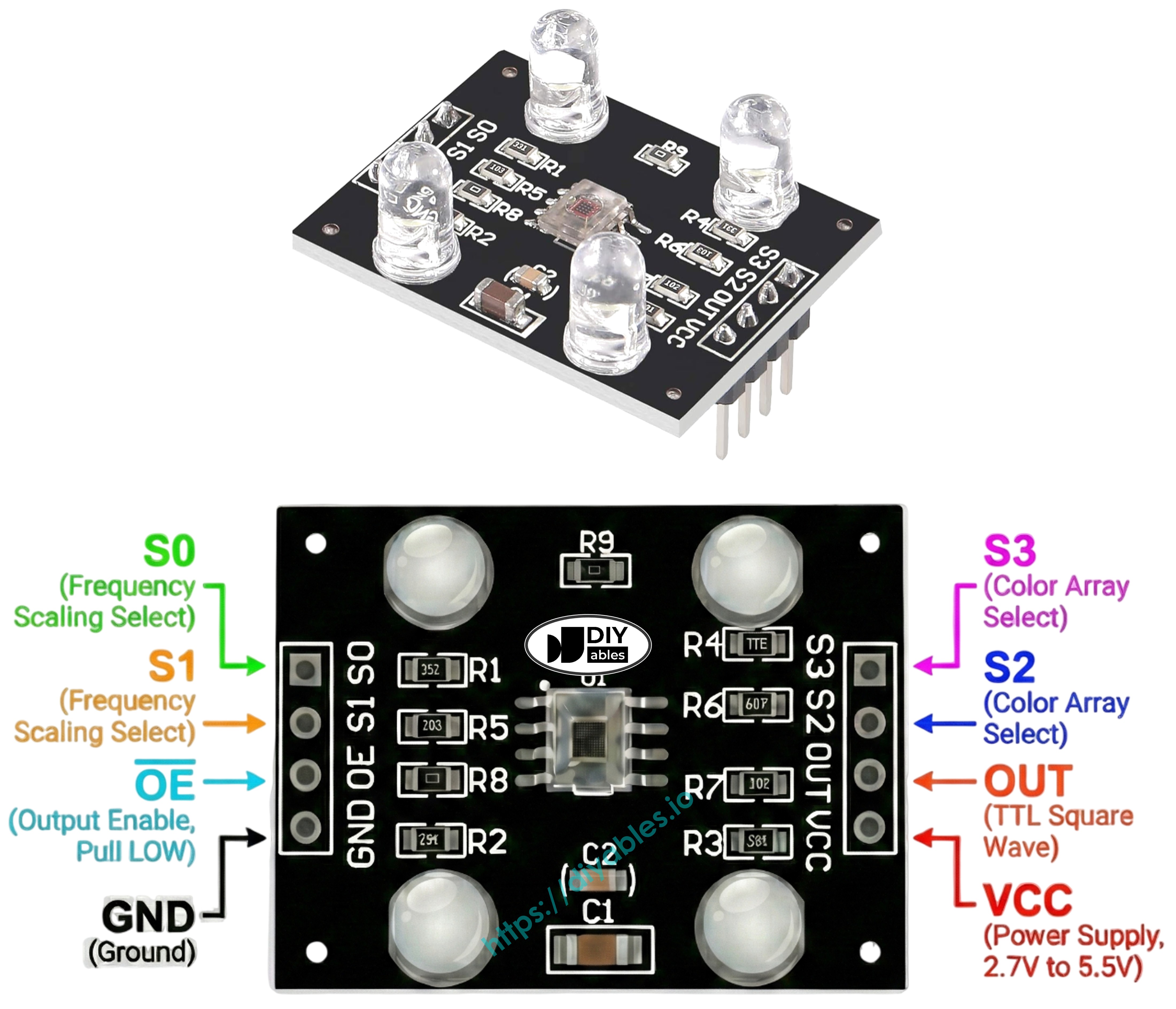
Pinout
The TCS3200D/TCS230 module provides the following connections:
- VCC pin: Power supply input (+5V).
- GND pin: Ground connection (0V).
- S0, S1 pins: Output frequency scaling control.
- S2, S3 pins: Photodiode color filter selection.
- OUT pin: Square wave frequency output.
- OE pin: Output enable control (active LOW). Most modules pre-wire this to GND. If unconnected, wire to GND manually.
How It Works
The sensor's operation depends on two control mechanisms: selecting which color channel to measure and setting the output frequency scaling. These are controlled by two pin pairs:
Output frequency scaling (S0 and S1 pins):
- S0=LOW, S1=LOW: Power down mode
- S0=LOW, S1=HIGH: 2% frequency scaling
- S0=HIGH, S1=LOW: 20% frequency scaling
- S0=HIGH, S1=HIGH: 100% frequency scaling (maximum)
Color filter selection (S2 and S3 pins):
- S2=LOW, S3=LOW: Red filter activated
- S2=LOW, S3=HIGH: Blue filter activated
- S2=HIGH, S3=LOW: Clear filter (no filtering)
- S2=HIGH, S3=HIGH: Green filter activated
The OUT pin outputs a square wave with frequencies typically ranging from 2 Hz to 500 kHz. Higher light intensity produces higher frequency output. The Arduino's pulseIn() function measures pulse width (duration), which varies inversely—stronger light creates shorter pulses. After calibration, these measurements convert to standard 0-255 RGB values.
Best Practices for Accuracy
- Maintain consistent sensor-to-target distance (1-3 cm) and angle.
- Use the built-in white LEDs for stable illumination.
- Minimize exposure to varying ambient light sources.
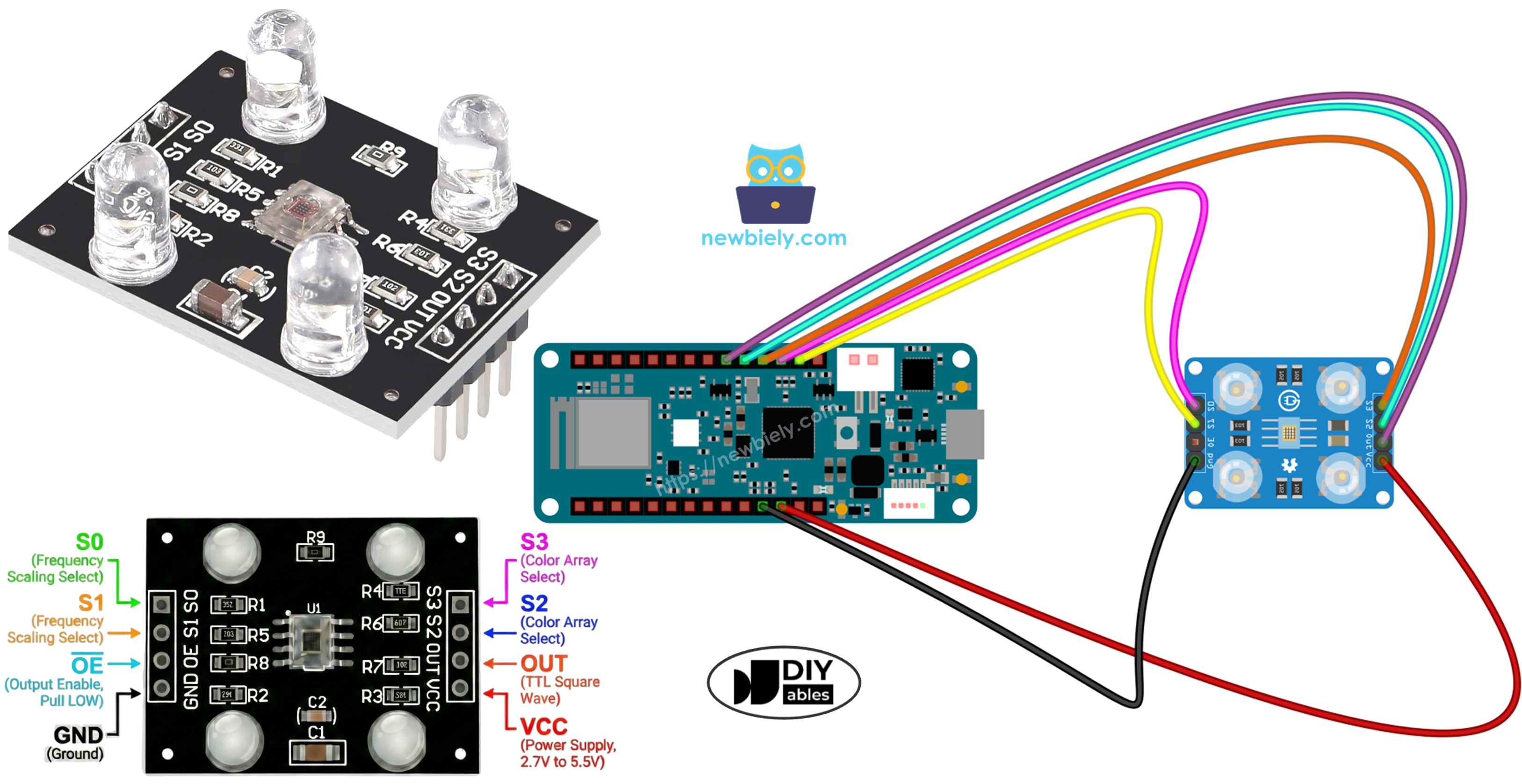
Wiring Diagram
Connect the TCS3200 color sensor to Arduino MKR WiFi 1010 as follows:
| TCS3200 Color Sensor | Arduino MKR WiFi 1010 |
|---|---|
| VCC | VCC (5V) |
| GND | GND |
| S0 | D16 |
| S1 | D15 |
| S2 | D18 |
| S3 | D17 |
| OUT | D19 |
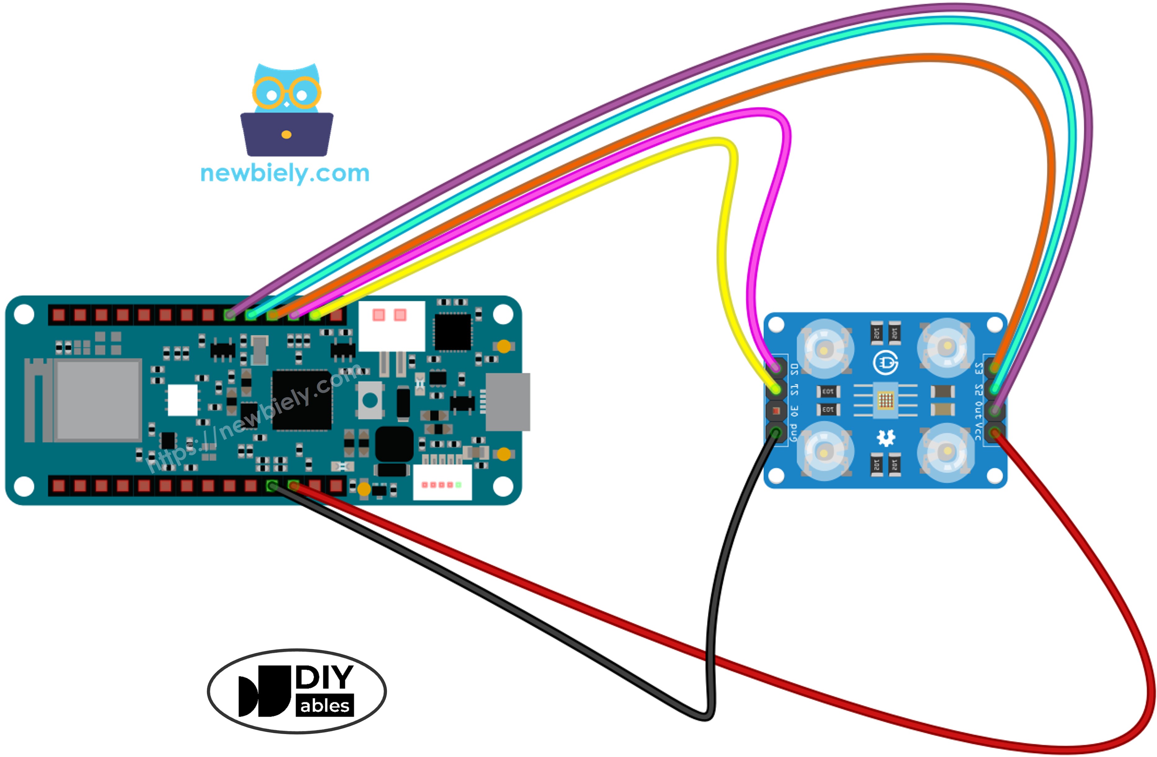
This image is created using Fritzing. Click to enlarge image
Arduino MKR WiFi 1010 Code - Calibration
Calibration compensates for environmental variations that affect sensor readings. Factors like LED brightness, target distance, surface reflectivity, and ambient lighting all influence raw measurements. The calibration process measures the minimum and maximum pulse widths for each color channel, establishing reference points that enable accurate conversion of raw sensor data to standardized 0–255 RGB values for your specific setup.
Detailed Instructions
- Open the calibration code in Arduino IDE
- Connect your Arduino MKR WiFi 1010 and click the Upload button
- Open Serial Monitor to view live calibration data
- Point the sensor at various surfaces: white (paper), black, and different colors
- Observe as the Min/Max values update automatically
- After readings stabilize (typically 10-20 seconds), record all six calibration values
Example calibration values from the output above:
- RedMin = 42, redMax = 210
- GreenMin = 55, greenMax = 185
- BlueMin = 60, blueMax = 172
Arduino MKR WiFi 1010 Code - Reading RGB Values
Detailed Instructions
- Locate the calibration variables at the top of the code:
- Replace the zero values with your actual calibration data. For example, using redMin = 42, redMax = 210, greenMin = 55, greenMax = 185, blueMin = 60, blueMax = 172:
- Upload the modified code to your Arduino MKR WiFi 1010
- Position a colored object in front of the sensor
- View the RGB values in Serial Monitor
The displayed RGB values follow the standard 0-255 range. Lower pulse widths (brighter colors) produce higher RGB values, while higher pulse widths (darker colors) produce lower values.
Project Applications
With RGB color detection working, you can create:
- Color sorting machine: Separate objects by color (red/green/blue detection)
- Color matching system: Compare colors between different objects
- Line following robot: Track colored lines or markers
- Color quality control: Detect color variations in manufacturing
- Color-based triggers: Activate different actions based on detected colors