Arduino MKR WiFi 1010 - LDR Module
Bring light detection to your Arduino MKR WiFi 1010 projects! The LDR light sensor module is a versatile component that detects light presence and measures brightness levels. Unlike simple photoresistors, this module offers both digital and analog outputs, giving you flexibility in how you work with light data in your Arduino MKR WiFi 1010 projects.
This comprehensive tutorial teaches you everything needed to interface an LDR module with Arduino MKR WiFi 1010. You'll learn how to read both output types from the LDR sensor using your Arduino MKR WiFi 1010, understand how the sensitivity adjustment works, and see practical examples of light detection with Arduino MKR WiFi 1010.
What You'll Learn:
- Wiring an LDR light sensor module to Arduino MKR WiFi 1010
- Programming Arduino MKR WiFi 1010 to detect light presence using the LDR module's digital output
- Using Arduino MKR WiFi 1010 to measure brightness levels with the LDR module's analog output
- Calibrating the LDR module's sensitivity for Arduino MKR WiFi 1010 projects
- Understanding how the LDR module works with Arduino MKR WiFi 1010
- Reading light sensor data on Arduino MKR WiFi 1010 Serial Monitor
Real-World Applications:
- Automatic lighting systems: Use Arduino MKR WiFi 1010 with LDR module to control lights based on ambient brightness
- Energy saving projects: Arduino MKR WiFi 1010 and LDR module for automated power management
- Security systems: Arduino MKR WiFi 1010 LDR sensor for detecting room entry via light changes
- Plant growth monitoring: Track sunlight exposure using Arduino MKR WiFi 1010 with LDR module
- Smart curtains: Arduino MKR WiFi 1010 and LDR module to automate window coverings
- Photography lighting: Monitor studio brightness with Arduino MKR WiFi 1010 LDR sensor
- Learning projects: Perfect LDR module project for Arduino MKR WiFi 1010 beginners
Once you master the basics, you can expand your Arduino MKR WiFi 1010 project by controlling LEDs, activating relays for larger appliances, or triggering servo motors based on light levels detected by the LDR module.
Looking for simpler alternatives? Check out the Arduino MKR WiFi 1010 - Light Sensor tutorial to learn about basic photoresistors with Arduino MKR WiFi 1010.
Hardware Preparation
| 1 | × | Arduino MKR WiFi 1010 | |
| 1 | × | Micro USB Cable | |
| 1 | × | LDR Light Sensor Module | |
| 1 | × | Breadboard | |
| 1 | × | Jumper Wires |
Or you can buy the following kits:
| 1 | × | DIYables Sensor Kit (18 sensors/displays) |
Additionally, some of these links are for products from our own brand, DIYables .
Overview of LDR Light Sensor Module
The LDR light sensor module is a ready-to-use breakout board that simplifies light detection in your Arduino MKR WiFi 1010 projects. Unlike bare photoresistors, this module includes built-in circuitry for signal conditioning and provides both digital and analog outputs, making it incredibly versatile for different applications.
Key Features:
- Dual output modes: Digital (HIGH/LOW) and analog (0-1023 range)
- Adjustable sensitivity: Built-in potentiometer for threshold calibration
- Visual indicators: Two LEDs show power status and detection state
- Wide voltage range: Works with 3.3V or 5V systems
- Easy interfacing: No external components needed
Pinout
The LDR light sensor module has four pins for easy connection to your Arduino MKR WiFi 1010:
- VCC pin: Connect to power supply (3.3V-5V). For Arduino MKR WiFi 1010, connect to the 3.3V or 5V pin.
- GND pin: Connect to ground (0V). Use any GND pin on your Arduino MKR WiFi 1010.
- DO pin: Digital output pin. Outputs HIGH in darkness, LOW in light. The threshold is adjustable via the onboard potentiometer.
- AO pin: Analog output pin. Provides values from 0-1023, where lower values indicate brighter light and higher values indicate dimmer conditions.
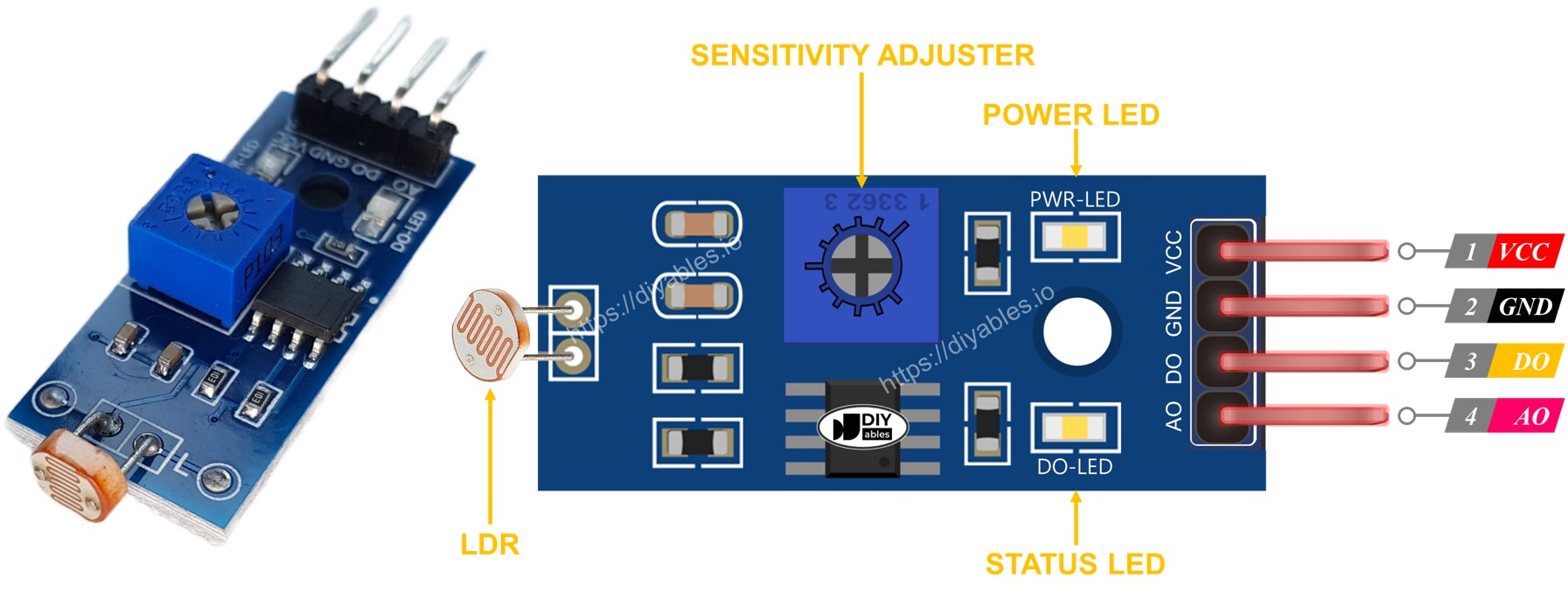
LED Indicators:
- PWR-LED (Power LED): Illuminates when the module receives power, confirming proper voltage connection.
- DO-LED (Detection LED): Mirrors the DO pin state - lights up when ambient light exceeds the threshold (DO pin LOW), turns off in darkness (DO pin HIGH).
How It Works
Understanding the two output modes helps you choose the right approach for your Arduino MKR WiFi 1010 project.
Digital Output (DO Pin):
The DO pin provides simple on/off light detection - perfect for triggering actions when light conditions cross a threshold.
- Adjustable threshold: Turn the onboard potentiometer to set your desired light level trigger point
- HIGH output: Sent when ambient light is below the threshold (dark conditions)
- LOW output: Sent when ambient light is above the threshold (bright conditions)
- Visual feedback: The DO-LED mirrors this output - it lights up when DO is LOW (bright), and turns off when DO is HIGH (dark)
Practical tip: Start by setting the potentiometer to mid-position, then adjust while observing the DO-LED response to your lighting conditions.
Analog Output (AO Pin):
The AO pin provides continuous brightness measurements ranging from 0 to 1023, ideal for precise light monitoring or creating smooth lighting responses.
- Inverse relationship: Higher light intensity = lower AO values, lower light intensity = higher AO values
- Full range: Typically ranges from ~50-100 in bright light to 800-1023 in darkness
- Independent operation: The potentiometer adjustment does not affect AO values - only the DO threshold
Why the inverse relationship? The photoresistor's resistance decreases with more light, which results in lower voltage (and thus lower ADC readings) on the analog pin. This is normal behavior for LDR modules.
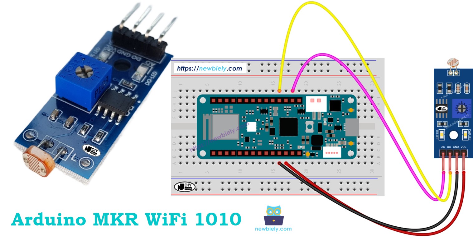
Wiring Diagram
The LDR module offers flexible connection options depending on your project needs. You can use just the digital output for simple light detection, just the analog output for precise measurements, or both outputs simultaneously for maximum versatility.
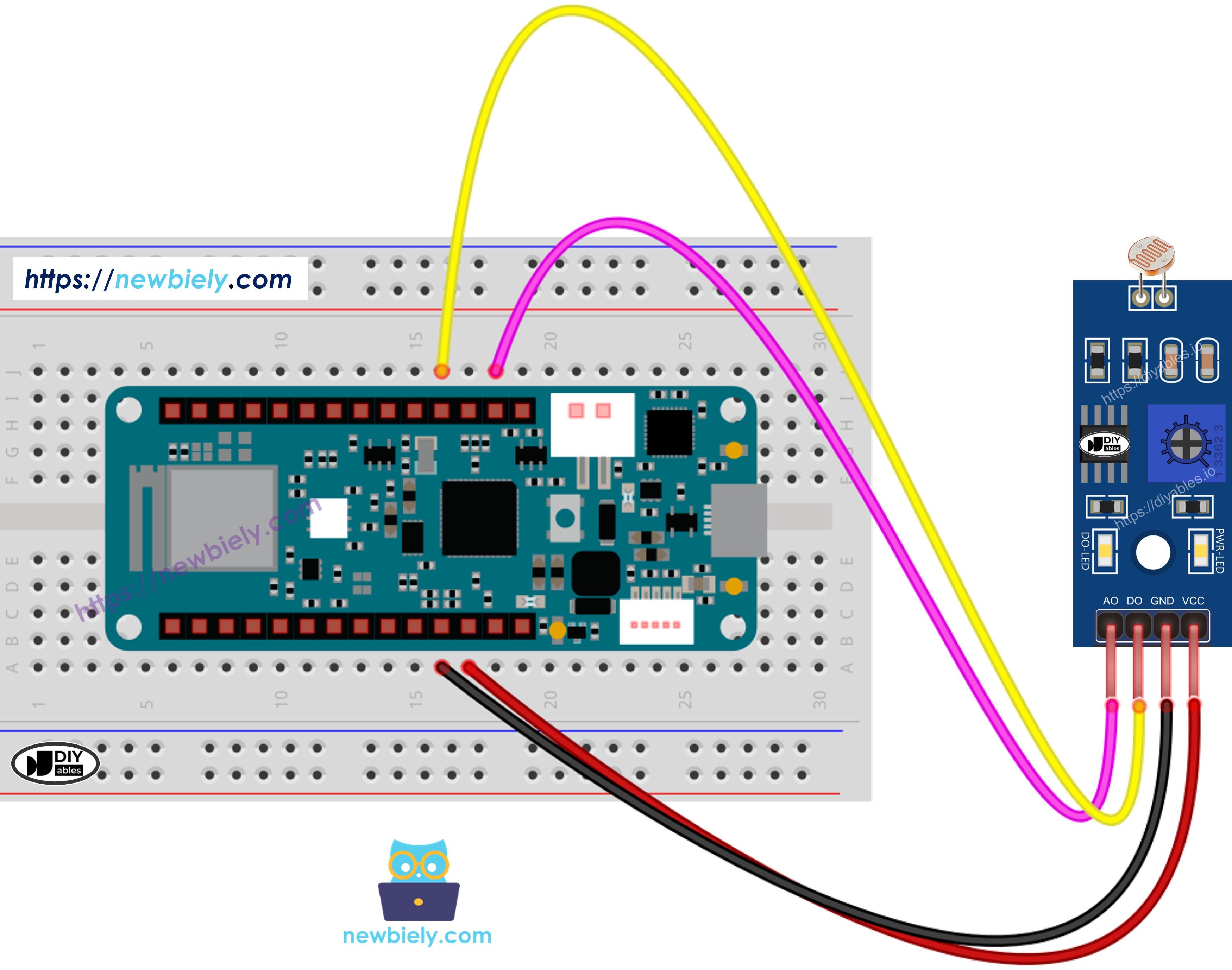
This image is created using Fritzing. Click to enlarge image
Connection tips:
- Always connect VCC and GND first before signal pins
- Double-check your connections before powering up
- Use the breadboard to keep connections organized
- The DO-LED provides instant visual feedback for testing
Arduino MKR WiFi 1010 Code - Read value from DO pin
This example demonstrates how to use the digital output of the LDR module with your Arduino MKR WiFi 1010. The code reads the DO pin and reports whether light is detected or not - perfect for triggering automatic actions based on lighting conditions.
Detailed Instructions
New to Arduino MKR WiFi 1010? Complete our Getting Started with Arduino MKR WiFi 1010 tutorial first to set up your development environment.
- Wire the LDR module to your Arduino MKR WiFi 1010 following the wiring diagram above (at minimum, connect VCC, GND, and DO pins)
- Connect your Arduino MKR WiFi 1010 to your computer using the Micro USB cable
- Open the Arduino IDE on your computer
- Select the correct board and COM port:
- Go to Tools > Board and select Arduino MKR WiFi 1010
- Go to Tools > Port and select the COM port your Arduino is connected to
- Copy the code above and paste it into a new Arduino IDE sketch
- Click the Upload button (right arrow icon) to compile and upload the code to your Arduino MKR WiFi 1010
- Open the Serial Monitor by clicking the magnifying glass icon or pressing Ctrl+Shift+M
- Test the sensor by covering and uncovering the LDR with your hand or any object
- Watch the Serial Monitor to see the light detection results
Troubleshooting tip: If the DO-LED stays constantly on or off regardless of lighting conditions, you need to adjust the sensitivity. Grab a small Phillips screwdriver and gently turn the potentiometer on the module while observing the LED. Turn clockwise to increase sensitivity (trigger in brighter conditions) or counterclockwise to decrease sensitivity (trigger only in darker conditions).
Next steps: Now that you have light detection working, you can expand your project! Control an LED to create automatic lighting, trigger a relay to switch larger appliances, or activate a servo motor for automated blinds. The digital output makes it easy to add light-based automation to any project.
Arduino MKR WiFi 1010 Code - Read value from AO pin
This example shows how to read the analog output of the LDR module with your Arduino MKR WiFi 1010. The code continuously reads brightness levels as numerical values (0-1023), perfect for data logging, creating smooth lighting responses, or monitoring ambient light conditions over time.
Detailed Instructions
- If you haven't already, wire the LDR module's AO pin to an analog pin on your Arduino MKR WiFi 1010 (as shown in the analog wiring diagram)
- Copy the code above and paste it into a new Arduino IDE sketch
- Click the Upload button to send the code to your Arduino MKR WiFi 1010
- Open the Serial Monitor (Ctrl+Shift+M or click the magnifying glass icon)
- Test the sensor by covering and uncovering the LDR with your hand or another object
- Observe the changing values in the Serial Monitor
Understanding the values:
- Low values (0-300): Bright light conditions
- Medium values (300-700): Normal indoor lighting
- High values (700-1023): Dim lighting or darkness
Remember that lower numbers mean brighter light! This inverse relationship is normal for LDR modules.
Project ideas with analog readings:
- Create a brightness graph by plotting values over time in the Arduino Serial Plotter
- Build a data logger that records light levels throughout the day
- Make smooth LED dimming that responds proportionally to ambient light
- Develop a smart window blind controller that adjusts based on sunlight intensity
- Design an alert system that notifies you when brightness falls below a certain level
Troubleshooting
Having issues with your LDR module? Here are solutions to common problems:
Problem: DO-LED stays always on or always off
- Cause: Potentiometer threshold not calibrated for your lighting conditions
- Solution: Use a small screwdriver to adjust the potentiometer while observing the DO-LED response. Turn slowly until it triggers at your desired light level
Problem: AO readings don't change much
- Cause: LDR not receiving enough light variation, or wiring issue
- Solution: Test by shining a flashlight directly on the LDR and completely covering it with your hand. Values should swing from very low to very high. If not, check your wiring connections
Problem: Erratic or unstable readings
- Cause: Loose connections, electrical noise, or fluctuating ambient light
- Solution:
- Check all wire connections are secure
- Keep wires short and away from power cables
- Add a small capacitor (0.1µF) between VCC and GND if noise persists
- Average multiple readings in code for stability
- Cause: No power or reversed polarity
- Solution: Verify VCC connected to 3.3V or 5V, GND to GND. Check polarity is correct
- Cause: This is normal! LDR modules output higher values in darkness
- Solution: No fix needed - this is expected behavior. Adjust your code logic accordingly
Problem: Module not powering on (no PWR-LED)
Problem: Sensor works but values seem inverted
Challenge Yourself - Creative Customizations
Now that your LDR module works, try these enhancements to build your skills:
Threshold-Based Actions
Expand the digital output example to trigger real-world actions:
Multi-Level Light Detection
Create zones instead of just light/dark:
Data Logging with Timestamps
Track light levels over time (requires RTC module):
Advanced Features to Try
- Sunrise/Sunset Alarm: Detect when room brightness crosses morning/evening thresholds and trigger actions
- Smart LED dimming: Use analogWrite() to dim LED inversely proportional to ambient light
- Plant growth monitoring: Log daily light exposure for houseplants
- Security system: Alert when light detected in room that should be dark
- Combine with DHT sensor: Create a complete environmental monitoring station
- LCD display: Show current light level and min/max values on 16x2 LCD
- Web dashboard: Send light data to cloud for remote monitoring
Related Tutorials:
- Arduino MKR WiFi 1010 - LED Control - Add automatic lighting
- Arduino MKR WiFi 1010 - Relay Module - Switch larger appliances
- Arduino MKR WiFi 1010 - Servo Motor - Automate blinds