Arduino MKR WiFi 1010 - LED - Blink
Welcome to the foundational Arduino MKR WiFi 1010 LED blink tutorial! This guide teaches you how to control an LED with your Arduino MKR WiFi 1010 board using simple digital output commands. Blinking an LED is the classic first project that every Arduino MKR WiFi 1010 beginner starts with - it's like the "Hello World" of electronics! In this tutorial, you'll learn to connect an LED to your Arduino MKR WiFi 1010, write code to control it, and understand the fundamental concepts of digital output that you'll use in virtually every Arduino MKR WiFi 1010 project you build.
What You'll Learn:
- Connecting an LED to Arduino MKR WiFi 1010 digital output pins
- Programming Arduino MKR WiFi 1010 to control LED on/off states
- Using pinMode() to configure Arduino MKR WiFi 1010 pins as outputs
- Understanding digitalWrite() for Arduino MKR WiFi 1010 digital control
- Implementing timing with delay() function on Arduino MKR WiFi 1010
- Building your first Arduino MKR WiFi 1010 circuit with LED and resistor
- Reading Arduino MKR WiFi 1010 code to control LED blinking patterns
Real-World Applications:
- Status indicators: Use Arduino MKR WiFi 1010 with LED to show system status (WiFi connected, data received, errors)
- Visual alarms: Arduino MKR WiFi 1010 LED blinking as warning signals for temperature alerts, motion detection
- Prototyping: Learning LED control with Arduino MKR WiFi 1010 before controlling more complex devices
- Device control: The same Arduino MKR WiFi 1010 code controls relays to switch motors, lights, or appliances on/off
- Robot indicators: Arduino MKR WiFi 1010 with LED showing robot states (searching, moving, found target)
- Home automation: Arduino MKR WiFi 1010 LED indicators for smart home device status
- Testing circuits: Use Arduino MKR WiFi 1010 LED for quick circuit testing and debugging
Hardware Preparation
| 1 | × | Arduino MKR WiFi 1010 | |
| 1 | × | Micro USB Cable | |
| 1 | × | LED Kit | |
| 1 | × | LED (red) | |
| 1 | × | LED Module | |
| 1 | × | Alternatively, Button and LED Kit | |
| 1 | × | 220Ω Resistor | |
| 1 | × | Breadboard | |
| 1 | × | Jumper Wires | |
| 1 | × | Optionally, DC Power Jack |
Or you can buy the following kits:
| 1 | × | DIYables Sensor Kit (18 sensors/displays) |
Additionally, some of these links are for products from our own brand, DIYables .
Buy Note: Use the LED Module for easier wiring. It includes an integrated resistor.
Overview of LED
An LED (Light Emitting Diode) is a semiconductor device that emits light when electrical current flows through it. LEDs are perfect for Arduino MKR WiFi 1010 projects because they're inexpensive, energy-efficient, and easy to control.
Why Use LEDs?
- Visual feedback: See when your Arduino MKR WiFi 1010 is running, processing, or detecting events
- Low power: LEDs consume very little current (typically 10-20mA)
- Long lasting: Can last for years of continuous operation
- Fast response: Turn on/off instantly for blinking or PWM brightness control
- Safe voltage: Work perfectly with Arduino MKR WiFi 1010's 3.3V logic levels
LED Pinout
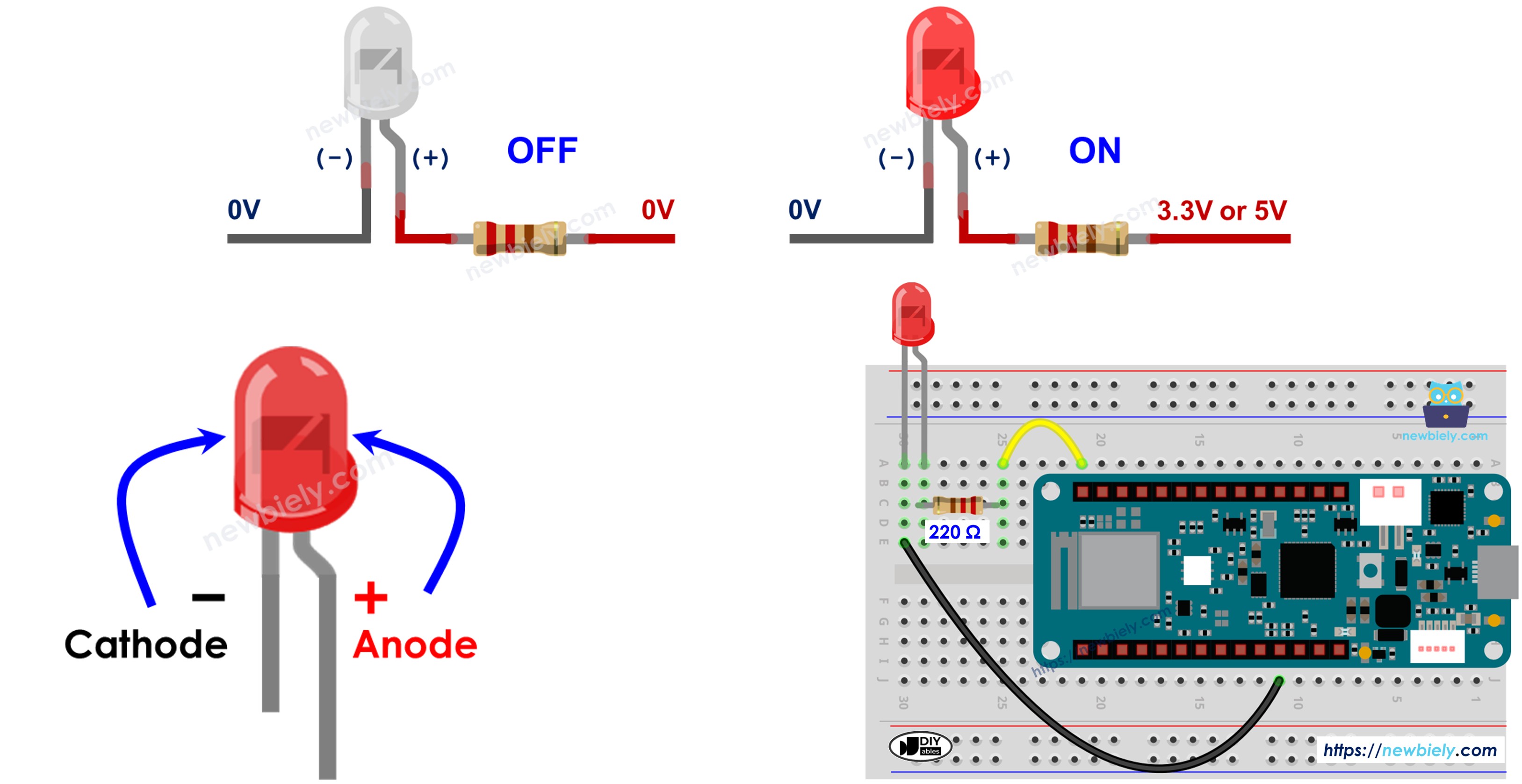
An LED has two pins that you need to identify correctly:
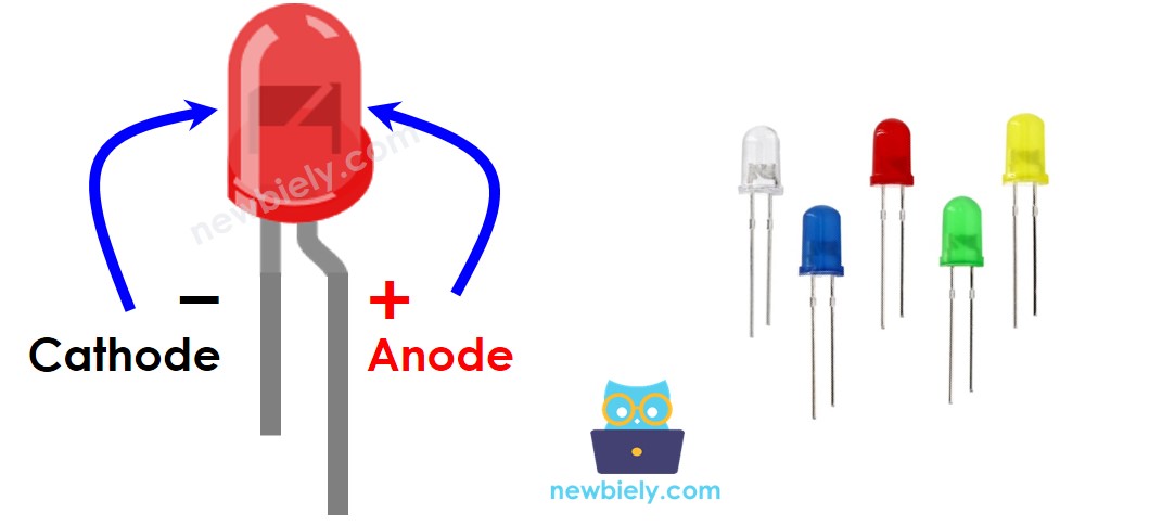
- Cathode (-) pin: The shorter leg, connects to ground (0 volts)
- Also indicated by flat edge on LED housing
- Anode (+) pin: The longer leg, connects to power source
- Use this pin to control the LED on/off state from your Arduino MKR WiFi 1010
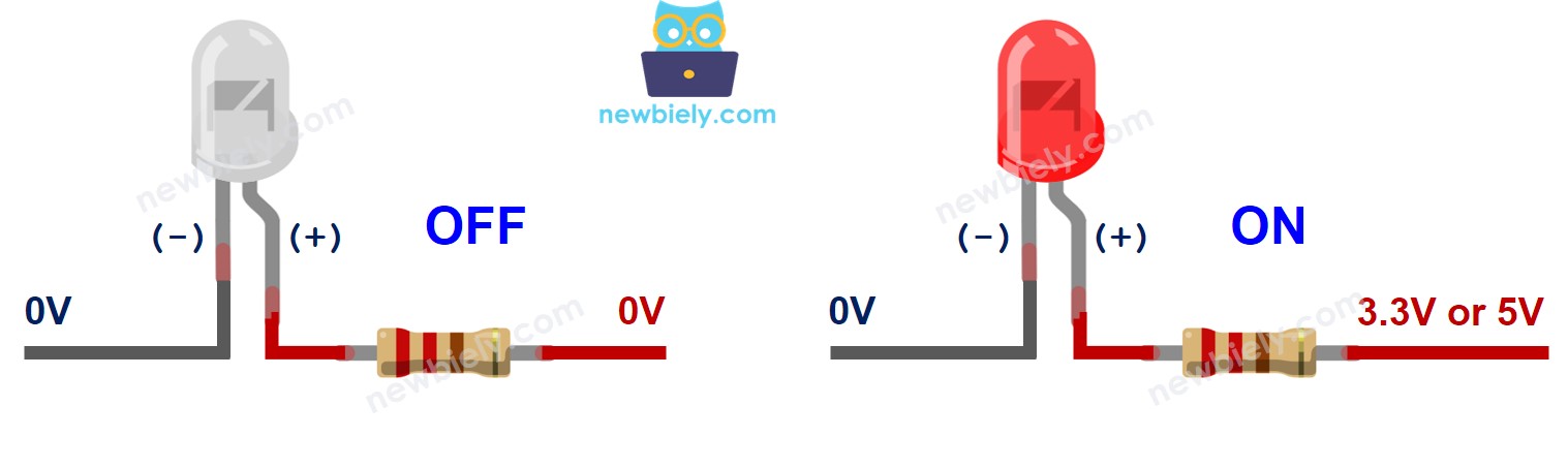
- Cathode connected to ground (GND)
- Anode receives HIGH signal (3.3V or 5V) → LED turns ON
- Anode receives LOW signal (0V/GND) → LED turns OFF
- Current-limiting resistor required: LEDs can burn out if they receive too much current. Always use a resistor (typically 220Ω-1kΩ) in series with your LED. The resistor can go between the LED anode (+) and power, or between the cathode (-) and ground - both work!
- Resistor value: The exact value depends on your LED's specifications and supply voltage. 220Ω is a safe value for most standard LEDs with Arduino MKR WiFi 1010.
- Built-in resistors: Some LED modules already have resistors built in, so you can connect them directly to Arduino MKR WiFi 1010 pins.
- digitalWrite(pin, HIGH): Pin outputs voltage → LED turns ON
- digitalWrite(pin, LOW): Pin outputs 0V (ground) → LED turns OFF
Important Tip: LEDs are polarity-sensitive - they only work when connected correctly. If your LED doesn't light up, try reversing it!
How LED Works
An LED lights up when current flows from the anode (+) to the cathode (-):
Basic Operation:
Brightness Control:
You can also control LED brightness by sending PWM (Pulse Width Modulation) signals to the anode. The LED brightness varies based on the PWM duty cycle. For details, see the Arduino MKR WiFi 1010 - Fade LED tutorial.
※ NOTE THAT:
Arduino MKR WiFi 1010 - LED Control
The Arduino MKR WiFi 1010 can control LEDs using its digital output pins. When you set a digital pin to OUTPUT mode, you can then control its voltage level:
By toggling between HIGH and LOW with delays in between, you create a blinking effect!
Wiring Diagram
Connect your LED to the Arduino MKR WiFi 1010 as shown in the diagram below:
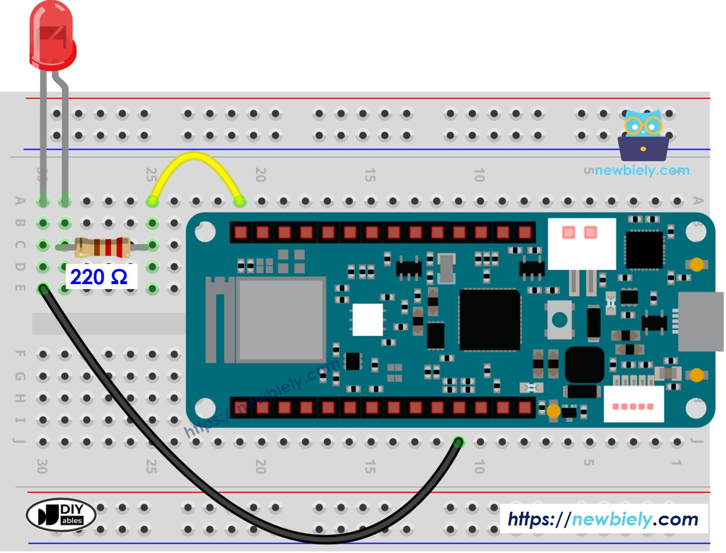
This image is created using Fritzing. Click to enlarge image
Connection Details:
- LED Anode (longer leg, +) → 220Ω Resistor → Arduino Pin D5
- The resistor limits current to protect the LED
- LED Cathode (shorter leg, -) → Arduino GND
- Provides return path for current
- Double-check the LED polarity - longer leg is positive (+)
- Make sure the resistor is in series with the LED (between pin and LED)
- Use the breadboard to make connections secure
- Keep wires short and neat for a cleaner circuit
Wiring Tips:
How To Program
Controlling an LED with Arduino MKR WiFi 1010 requires three simple steps:
Step 1: Configure Pin as Output
Set an Arduino MKR WiFi 1010 pin to work as a digital output using the pinMode() function. For example, configure pin D5:
This tells the Arduino MKR WiFi 1010 that pin 5 will send signals out, not receive them.
Step 2: Turn LED OFF
Set the pin to LOW (0V, same as ground) using digitalWrite() to turn the LED off:
When the pin is at 0V, no current flows through the LED.
Step 3: Turn LED ON
Set the pin to HIGH (3.3V) using digitalWrite() to turn the LED on:
When the pin outputs 3.3V, current flows through the resistor and LED, making it light up!
Creating a Blink Pattern:
To make the LED blink, alternate between HIGH and LOW states with delays in between. This is exactly what the code below demonstrates.
Arduino MKR WiFi 1010 Code
Detailed Instructions
New to Arduino MKR WiFi 1010? Complete our Getting Started with Arduino MKR WiFi 1010 tutorial first to set up your development environment.
Step 1: Build the Circuit
- Connect the components to the Arduino MKR WiFi 1010 board following the wiring diagram
- Double-check LED polarity (longer leg to resistor, shorter leg to GND)
Step 2: Connect Arduino
- Plug your Arduino MKR WiFi 1010 into your computer's USB port
- Wait for your computer to recognize the board
Step 3: Prepare Arduino IDE
- Launch the Arduino IDE on your computer
- Select the Arduino MKR WiFi 1010 board from Tools > Board menu
- Select the correct COM port from Tools > Port menu
Step 4: Upload Code
- Click the Upload button (right arrow icon) in the Arduino IDE
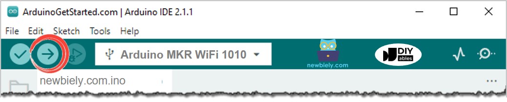
- Wait for "Done uploading" message
Step 5: See the Result
- Watch your LED blink on and off!
- The LED should flash once per second (500ms on, 500ms off)
- If the LED doesn't light up, check your wiring and LED polarity
Experiment with Timing:
Try changing the delay values in the code to create different blink patterns:
- delay(100) - Fast blink (5 times per second)
- delay(1000) - Slow blink (once every 2 seconds)
- delay(250) and delay(750) - Uneven blink (quick flash, long pause)
Code Explanation
The code above demonstrates a simple LED blink pattern:
setup() Function:
- Runs once when Arduino MKR WiFi 1010 powers on
- Configures digital pin D5 as an output
- Prepares the pin to control the LED
loop() Function:
- Repeats continuously as long as the Arduino MKR WiFi 1010 is powered
- Sets pin HIGH → LED lights up → waits 500ms
- Sets pin LOW → LED turns off → waits 500ms
- Result: LED blinks on and off every half second
※ NOTE THAT:
Important Note about delay(): The code above uses the delay() function, which pauses all Arduino MKR WiFi 1010 operations. This is fine for simple projects, but can be a problem if you need your Arduino MKR WiFi 1010 to do multiple tasks at once. For a non-blocking alternative, see Arduino MKR WiFi 1010 - Blink Without Delay.
Challenge Yourself - Creative Customizations
Once you have the basic LED blinking, try these variations to enhance your skills:
1. Different Blink Patterns
Create unique patterns by varying the delays:
2. Multiple LEDs
Connect and control multiple LEDs at different pins:
3. Brightness Fading
Use PWM to create a pulsing effect:
4. Button-Controlled LED
Add a button to turn the LED on/off:
5. Random Blinking
Create unpredictable patterns:
Experiment with these ideas and create your own unique LED projects!