Arduino MKR WiFi 1010 - Water Sensor
Learn how to use the Arduino MKR WiFi 1010 with a water sensor to detect water leaks, monitor rainfall, prevent tank overflows, and measure water levels in your projects. Water sensors are essential components for building smart home systems, flood detection alarms, automatic plant watering, aquarium monitoring, basement leak detection, rain gauges, washing machine overflow protection, and agricultural irrigation control. In this comprehensive tutorial, you'll discover how to connect a water sensor to your Arduino MKR WiFi 1010 board, read analog water level values, detect water presence, calibrate sensitivity, implement corrosion-resistant power control, set up leak alerts with LEDs and buzzers, and create multi-level monitoring systems. This guide includes complete wiring diagrams, working example code with detailed explanations, troubleshooting tips for sensor corrosion and inaccurate readings, and 10 creative challenge projects to expand your Arduino MKR WiFi 1010 water sensor applications. Whether you're building a basement flood alarm, plant watering system, water tank monitor, rain gauge, or leak detector for your Arduino MKR WiFi 1010, this tutorial provides everything you need to work with water sensors effectively.
Hardware Preparation
| 1 | × | Arduino MKR WiFi 1010 | |
| 1 | × | Micro USB Cable | |
| 1 | × | Water level sensor | |
| 1 | × | Breadboard | |
| 1 | × | Jumper Wires | |
| 1 | × | Optionally, DC Power Jack |
Or you can buy the following kits:
| 1 | × | DIYables Sensor Kit (18 sensors/displays) |
Additionally, some of these links are for products from our own brand, DIYables .
Overview of Water Level Sensor
A water sensor (also called water level sensor or water detector) is an analog sensor that detects the presence and level of water by measuring electrical conductivity between exposed traces on its circuit board. When water bridges these conductive traces, it creates electrical pathways that produce a proportional voltage output. Water sensors are commonly used in leak detection systems, flood alarms, rain gauges, aquarium monitors, plant watering automation, and tank overflow prevention. The Arduino MKR WiFi 1010 reads this analog voltage through its ADC (Analog-to-Digital Converter) to determine water presence and approximate depth.
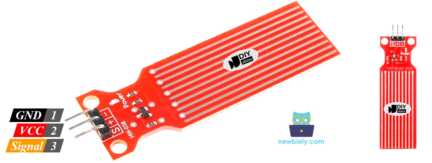
Water Level Sensor Pinout
The water level sensor has 3 pins:
- S (Signal) pin: Analog output that provides voltage proportional to water level
- Voltage increases as more traces are submerged
- Range: 0V (dry) to ~5V (fully submerged)
- Connect to any Arduino MKR WiFi 1010 analog pin (A0-A6)
- Arduino reads as 0-1023 value (10-bit ADC)
- + (VCC) pin: Power supply input
- Accepts 3.3V or 5V power
- Current consumption: ~20mA when active
- Important: Control power with digital pin to prevent corrosion
- Constant power causes rapid sensor degradation
- - (GND) pin: Ground connection
- Connect to Arduino GND pin
- Completes circuit for measurements
- Dry state: Traces are separated by air (insulator), minimal current flows → Output: 0V
- Water contact: Water bridges conductive traces, creating electrical pathways
- Increasing depth: More traces get submerged → More parallel pathways → Higher conductivity
- Voltage output: Signal voltage increases proportionally to water coverage area
- Arduino reads: ADC converts analog voltage (0-5V) to digital value (0-1023)
- Level interpretation: Software maps reading to water levels (empty, low, medium, high)
- Detection range: 0-40mm water depth on sensing area
- Response time: ~50ms (nearly instant detection)
- Sensitivity: Proportional to trace coverage (not absolute depth)
- Limitations: Detects presence and approximate level, not precise depth
- Water quality: Readings vary with conductivity (pure water vs. tap water vs. saltwater)
- Corrosion issue: Electrolysis occurs when continuously powered in water → Trace degradation
How Water Level Sensor Works
The water sensor operates using conductivity-based detection:
Detection Process:
Key Characteristics:
Wiring Diagram
Power Options:
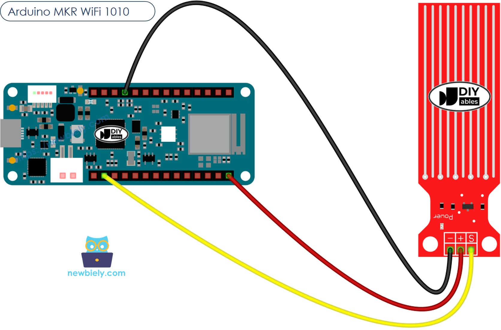
You can power the water sensor by connecting its VCC pin to the 3.3V or 5V pin and its GND pin to GND on the Arduino MKR WiFi 1010.
⚠️ Important - Prevent Corrosion:
Constantly powering the water sensor causes rapid corrosion and sensor failure. When VCC is connected continuously, electrolysis degrades the conductive traces within hours to days, especially in tap water or saltwater. Best practice: Connect the sensor's VCC pin to a digital pin on the Arduino MKR WiFi 1010 (instead of the 3.3V pin). Program that pin HIGH only when taking readings, then LOW immediately after. This extends sensor lifespan from days to months.
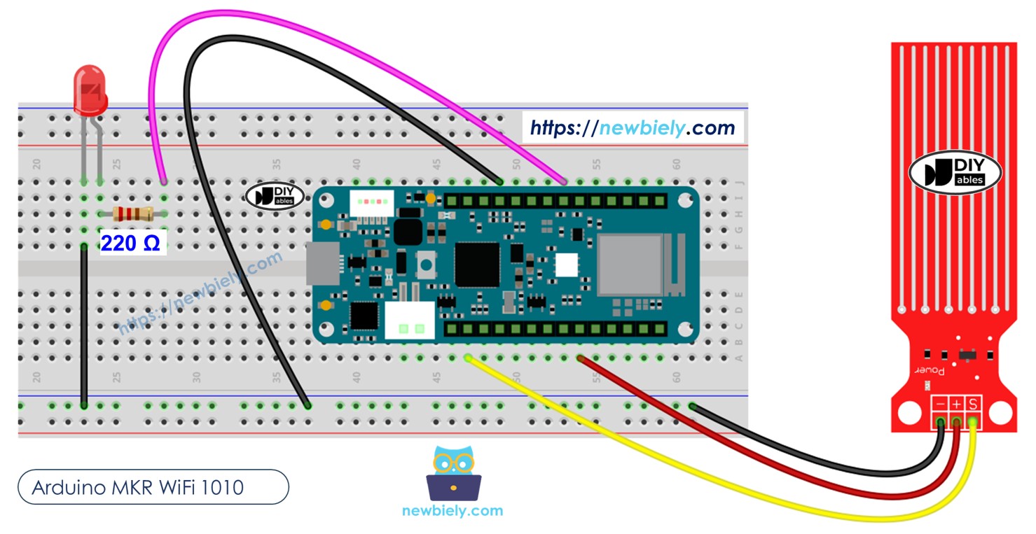
Corrosion-Resistant Wiring:
Simple Wiring (Not Recommended for Long-Term):
For quick testing only, you can connect VCC directly to 3.3V, but expect sensor degradation.
This image is created using Fritzing. Click to enlarge image
Power Supply Notes:
- Simply plug your Arduino MKR WiFi 1010 into your computer's USB port
- The water sensor draws only 20mA when active, well within USB power limits
- Use 5V power for maximum sensitivity (wider voltage range)
- 3.3V power works but provides lower maximum readings
Arduino MKR WiFi 1010 Code - Reading Value from Water Sensor
Detailed Instructions
New to Arduino MKR WiFi 1010? Complete our Getting Started with Arduino MKR WiFi 1010 tutorial first to set up your development environment.
- Connect the components to the Arduino MKR WiFi 1010 board as depicted in the diagram
- Plug your Arduino MKR WiFi 1010 into your computer's USB port
- Launch the Arduino IDE on your computer
- Select the Arduino MKR WiFi 1010 board and its COM port
- Copy the code above and paste it into the Arduino IDE
- Click the Upload button to compile and upload
- Slowly lower the sensor into a glass of water (do not fully submerge the circuit board)
- Watch the Serial Monitor as readings change from 0 (dry) to higher values (wet)
※ NOTE THAT:
The water sensor is not meant to be completely underwater. Only the parts that are meant to be wet on the circuit board can touch the water. Please be careful when installing it.
How To Detect Water Leakage
To find water leaks, rain, or a tank overflow, you only need to compare the sensor reading with a set limit. This limit is chosen during the calibration step of this guide.
Let's program the Arduino MKR WiFi 1010 to turn on an LED when it detects a water leak.
Wiring Diagram
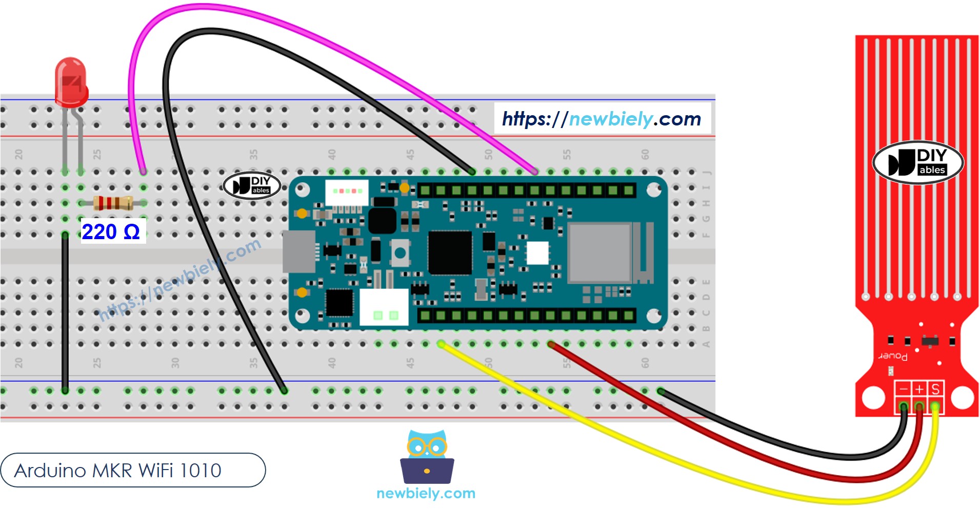
This image is created using Fritzing. Click to enlarge image
Arduino MKR WiFi 1010 Code - Detecting Water Leakage
How To Measure The Water Level
The following code splits the water level into four parts.
※ NOTE THAT:
SENSOR_MIN and SENSOR_MAX are set during the calibration process. The mapping method above is not perfectly accurate, but it works well for many uses.
Water Level Sensor Calibration
Check out this guide to learn how to adjust the water level sensor: https://arduinogetstarted.com/tutorials/arduino-water-sensor#content_water_level_sensor_calibration
Troubleshooting
Problem: Sensor always reads 0 even when in water
- Check wiring: Verify S pin is connected to analog pin (A1 not D1)
- Check power: If using controlled power, ensure digitalWrite(powerPin, HIGH) before reading
- Verify analog pin: Use A0-A6 (not digital pins) for analogRead()
- Test with Serial Monitor:
- Check dry reading: Should be 0-50 when completely dry
- Test with wet finger: Touch sensor traces, value should increase
Problem: Readings are erratic or jumping around
- Use averaging: Take multiple readings and calculate average:
- Add stabilization delay: Wait 10-50ms after power-on before reading
- Check water quality: Pure distilled water conducts poorly (add tiny pinch of salt)
- Electromagnetic interference: Keep away from motors, relays during reading
Problem: Sensor stops working after a few days
- Corrosion damage: Traces oxidized from constant power
- Solution: Use controlled power (HIGH only during reading, LOW after)
- Prevention code:
- Coating option: Apply clear nail polish to traces (reduces sensitivity but prevents corrosion)
- Replacement: Keep spare sensors if used in critical applications
Problem: Readings don't reach maximum value (stuck at 200-400)
- Insufficient submersion: Lower sensor deeper into water
- Power issue: Use 5V instead of 3.3V for higher voltage range:
- Recalibrate: Adjust SENSOR_MAX value in code to match your actual maximum reading
- Water conductivity: Tap water gives higher readings than distilled water
Problem: False triggers (detects water when dry)
- Add threshold: Set minimum detection value (ignore noise):
- Humidity issue: High humidity can cause low readings even when dry
- Test in target environment: Calibrate threshold for your specific conditions
- Dry thoroughly: Ensure sensor is completely dry for baseline reading
Challenge Extensions
Ready to take your water sensor project to the next level? Try these challenges:
Challenge 1: Basement Flood Alarm
Create a loud alarm system that activates when water is detected:
Challenge 2: Automatic Plant Watering System
Control a water pump based on soil moisture:
Challenge 3: Multi-Level Water Tank Monitor
Use multiple sensors at different heights to monitor tank levels:
Challenge 4: WiFi-Connected Leak Notifier
Send notifications to your phone when leaks are detected:
Challenge 5: Rain Gauge with LCD Display
Measure rainfall and display accumulation on LCD:
Challenge 6: Water Level Bar Graph with LEDs
Display water level visually using LED strip:
Challenge 7: Data Logger to SD Card
Log water level readings with timestamps:
Challenge 8: Washing Machine Overflow Protection
Shut off water valve when overflow detected:
Challenge 9: Aquarium Auto-Top-Off System
Maintain constant water level in aquarium:
Challenge 10: Smart Sump Pump Controller
Activate sump pump based on water level with safety features: