Arduino MKR WiFi 1010 - Rotary Encoder
Arduino MKR WiFi 1010 - Rotary Encoder
Want to add a rotary encoder to your Arduino MKR WiFi 1010 project for precise control? In this tutorial, you’ll connect a rotary encoder to an Arduino MKR WiFi 1010, upload code to the Arduino MKR WiFi 1010, and track the rotary encoder’s direction and position in the Serial Monitor.
What you’ll learn (Arduino MKR WiFi 1010 + rotary encoder):
- Connecting a rotary encoder to the Arduino MKR WiFi 1010
- Programming the Arduino MKR WiFi 1010 to read rotary encoder direction and position
- Using interrupts on the Arduino MKR WiFi 1010 for better rotary encoder performance
- Detecting button presses on the rotary encoder with the Arduino MKR WiFi 1010
Real-world uses for Arduino MKR WiFi 1010 and rotary encoder:
- Volume controls (Arduino MKR WiFi 1010 + rotary encoder for audio)
- Menu navigation (Arduino MKR WiFi 1010 reads rotary encoder clicks)
- Motor speed adjustment (Arduino MKR WiFi 1010 + rotary encoder)
- Learning input devices on Arduino MKR WiFi 1010
You’ll see the Arduino MKR WiFi 1010 print rotary encoder data as you turn the knob clockwise or counterclockwise.
Hardware Preparation
| 1 | × | Arduino MKR WiFi 1010 | |
| 1 | × | Micro USB Cable | |
| 1 | × | Rotary Encoder | |
| 1 | × | Breadboard | |
| 1 | × | Jumper Wires |
Or you can buy the following kits:
| 1 | × | DIYables Sensor Kit (18 sensors/displays) |
Additionally, some of these links are for products from our own brand, DIYables .
Overview of Rotary Encoder
A rotary encoder is like a knob that tells your Arduino MKR WiFi 1010 exactly how it’s being turned. Unlike a simple button, it detects direction and how many “clicks” you’ve made.
There are two main types:
- Incremental encoder: Tracks relative movement (like steps up or down).
- Absolute encoder: Remembers its position even after power off.
This tutorial focuses on the incremental rotary encoder, which is perfect for most Arduino MKR WiFi 1010 projects.
Rotary Encoder Module Pinout
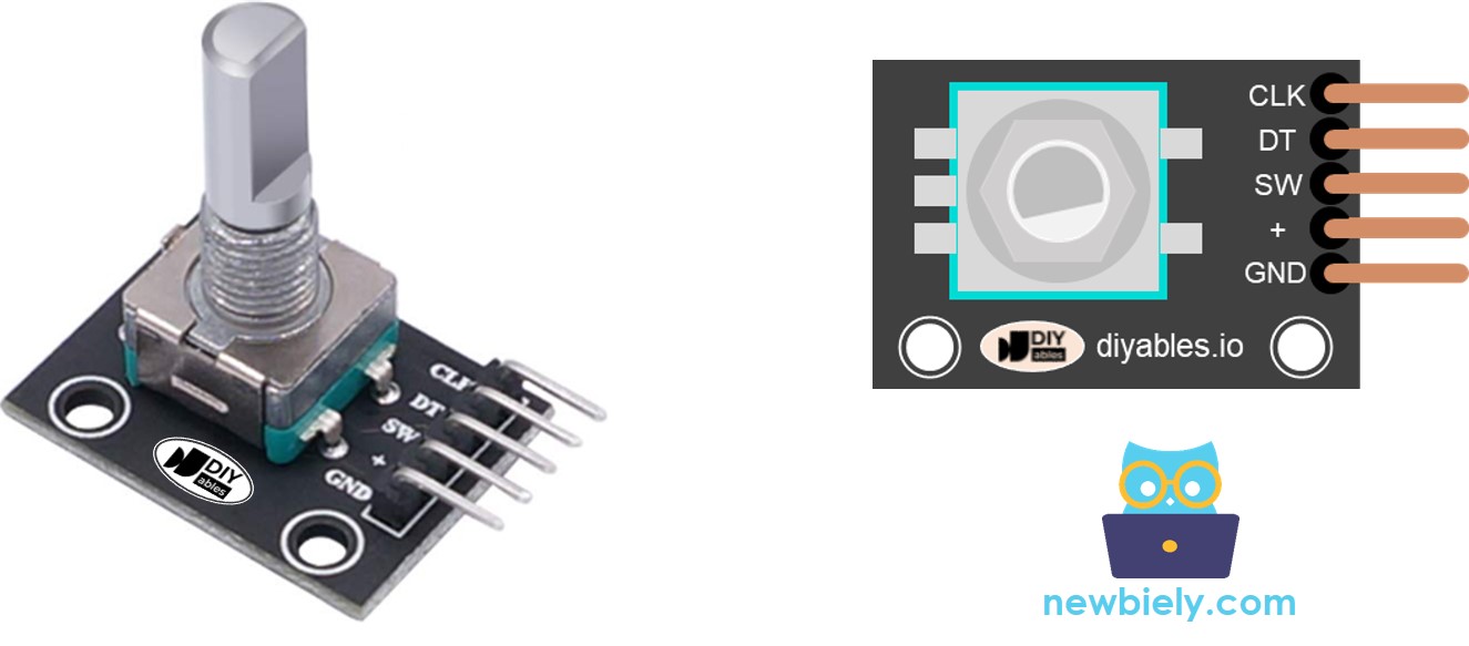
The rotary encoder has these pins:
- CLK (Output A): Sends pulses as you turn the knob.
- DT (Output B): Helps detect the direction of rotation.
- SW: The button pin (HIGH when not pressed, LOW when pressed).
- VCC: Power (3.3V to 5V).
- GND: Ground.
Rotary Encoder vs Potentiometer
| Feature | Rotary Encoder | Potentiometer |
|---|---|---|
| Rotation | Unlimited (full circle) | Limited (quarter to half circle) |
| Output | Digital pulses | Analog voltage |
| Position tracking | Relative (steps) | Absolute (exact angle) |
| Best for | Counting turns | Precise positioning |
How Rotary Encoder Works
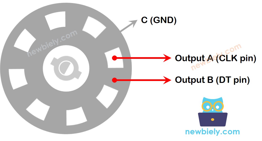
Inside, a disk with slots creates signals as you turn it. The Arduino MKR WiFi 1010 reads these to figure out direction and steps.
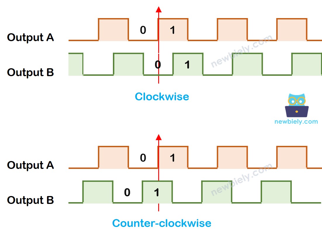
When CLK goes from LOW to HIGH:
- If DT is HIGH, it’s counterclockwise.
- If DT is LOW, it’s clockwise.
※ NOTE THAT:
Pin A and Pin B are connected to the CLK and DT pins. However, some manufacturers might use a different order. The code below has been tested with the rotary encoder from DIYables.
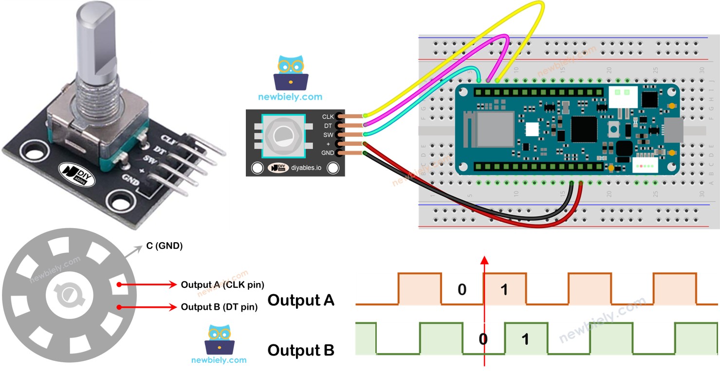
Wiring Diagram
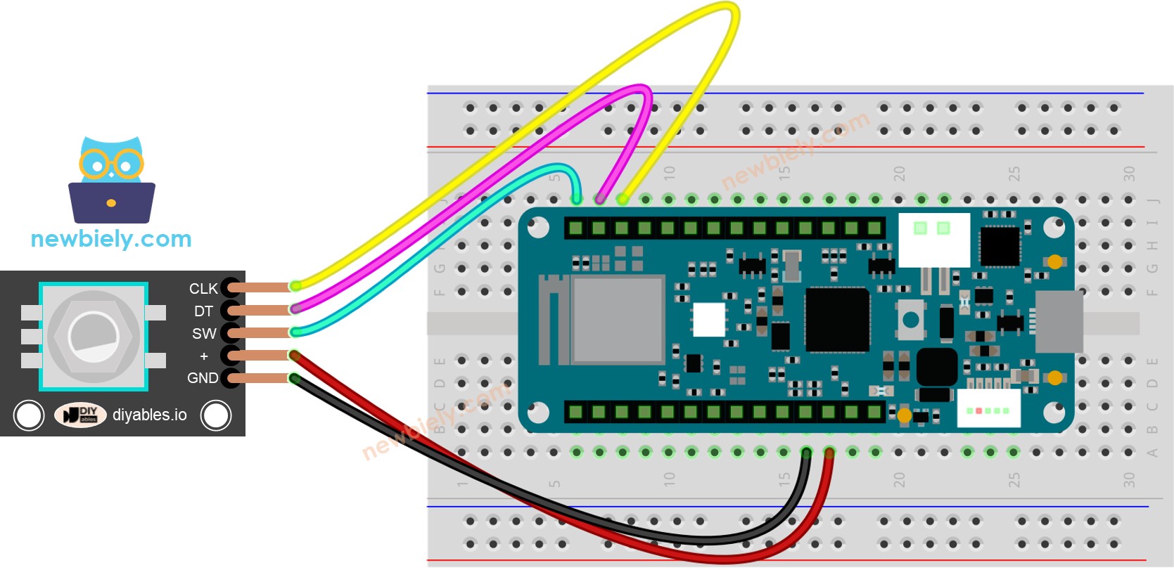
This image is created using Fritzing. Click to enlarge image
Wiring Table
| Rotary Encoder | Arduino MKR WiFi 1010 |
|---|---|
| CLK | D3 |
| DT | D4 |
| SW | D5 |
| VCC | 3.3V |
| GND | GND |
Arduino MKR WiFi 1010 Code – Rotary Encoder
This code reads the rotary encoder’s direction and position without interrupts. It also detects button presses.
We use the ezButton library to simplify button handling.
Detailed Instructions
New to Arduino MKR WiFi 1010? Complete our Getting Started with Arduino MKR WiFi 1010 tutorial first to set up your development environment.
- Connect the rotary encoder to the Arduino MKR WiFi 1010 as shown in the wiring diagram.
- Plug your Arduino MKR WiFi 1010 into your computer’s USB port.
- Open the Arduino IDE.
- Select the Arduino MKR WiFi 1010 board and correct COM port.
- Install the ezButton library from the Library Manager.
- Copy the code and paste it into a new sketch.
- Click Upload to compile and upload to the Arduino MKR WiFi 1010.
- Turn the knob right, then left.
- Press the knob.
- Check the Serial Monitor for output.
Arduino MKR WiFi 1010 Code – Rotary Encoder with Interrupt
For better performance, use interrupts to avoid missing steps. This code uses an interrupt on the Arduino MKR WiFi 1010.
※ NOTE THAT:
- Some guides on other sites might tell you to use two interrupts for one encoder, but you only need one.
- Always add the word volatile for global variables used in the interrupt. If you skip this, you might get strange errors.
- Keep the code inside the interrupt as simple as possible. Do not use Serial.print() or Serial.println() in the interrupt.
Arduino MKR WiFi 1010 Rotary Encoder Application
Using a Rotary Encoder, you can use it for many different tasks, including these:
- Arduino MKR WiFi 1010 – The rotary knob changes the servo motor's position
- Arduino MKR WiFi 1010 – The rotary knob adjusts the LED brightness
- Arduino MKR WiFi 1010 – The rotary knob controls the stepper motor's speed
Troubleshooting
- No output in Serial Monitor: Confirm COM port and baud rate match the code.
- Missed steps: Switch to the interrupt version of the code.
- Button not working: Check wiring and pull-up resistor.
- Erratic readings: Use shorter wires and ensure stable power.
Challenge Yourself - Creative Customizations
Once your Arduino MKR WiFi 1010 reads the rotary encoder reliably, try these ideas:
Quick Variations
- Add min/max limits to the counter.
- Change the step size (e.g., count by 2 instead of 1).
Advanced Features to Try
- Control an LED’s brightness with the rotary encoder.
- Use the encoder to navigate a menu on an LCD display.
- Combine with a servo motor for position control.
- Add multiple encoders for multi-axis control.