Arduino MKR WiFi 1010 - Solenoid Lock
Control electronic locks remotely! The solenoid lock (electric strike lock) provides secure electronic locking for cabinets, doors, and enclosures. This tutorial teaches you how to connect a solenoid lock to your Arduino MKR WiFi 1010 and program it for automated access control.
What You'll Learn:
- Connecting solenoid lock to Arduino MKR WiFi 1010 via relay
- Programming Arduino MKR WiFi 1010 to control solenoid lock states
- Using Arduino MKR WiFi 1010 relay module for high-voltage switching
- Building Arduino MKR WiFi 1010 access control with solenoid lock
- Understanding solenoid lock operation with Arduino MKR WiFi 1010
- Creating Arduino MKR WiFi 1010 timed lock systems
- Implementing Arduino MKR WiFi 1010 keypad-controlled solenoid locks
- Designing Arduino MKR WiFi 1010 security systems with electronic locks
Real-World Applications:
- Smart locks: Arduino MKR WiFi 1010 controlling door access remotely
- Cabinet security: Arduino MKR WiFi 1010 with solenoid lock protecting valuables
- Lockers: Arduino MKR WiFi 1010 managing multi-unit storage systems
- Vending machines: Arduino MKR WiFi 1010 releasing compartments on payment
- Hotel rooms: Arduino MKR WiFi 1010 solenoid locks with keycard access
- Parking barriers: Arduino MKR WiFi 1010 controlling gate mechanisms
- Safe boxes: Arduino MKR WiFi 1010 and solenoid lock with PIN entry
- Mailboxes: Arduino MKR WiFi 1010 automated mail delivery access
Alternative Option:
For heavier-duty applications, consider the electromagnetic lock. See the Arduino MKR WiFi 1010 Electromagnetic Lock tutorial for comparison.
Hardware Preparation
| 1 | × | Arduino MKR WiFi 1010 | |
| 1 | × | Micro USB Cable | |
| 1 | × | Solenoid Lock | |
| 1 | × | Relay | |
| 1 | × | 12V Power Adapter | |
| 1 | × | Breadboard | |
| 1 | × | Jumper Wires | |
| 1 | × | Optionally, DC Power Jack |
Or you can buy the following kits:
| 1 | × | DIYables Sensor Kit (18 sensors/displays) |
Additionally, some of these links are for products from our own brand, DIYables .
Overview of Solenoid Lock
What is a Solenoid Lock?
A solenoid lock (also called electric strike lock) is an electromechanical locking device that uses electromagnetic force to extend or retract a bolt, controlling access to doors, cabinets, and enclosures.
How Solenoid Locks Work:
Key Characteristics:
- Operating voltage: 12V, 24V, or 48V DC (most common: 12V)
- Current draw: 200-500mA (depending on model)
- Lock modes: Fail-secure (locked when unpowered) or fail-safe (unlocked when unpowered)
- Holding force: 10-50 kg depending on model
- Response time: <100ms lock/unlock
- Duty cycle: Typically 100% (can remain locked continuously)
Solenoid Lock vs Electromagnetic Lock:
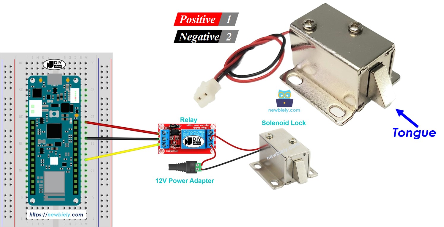
Pinout
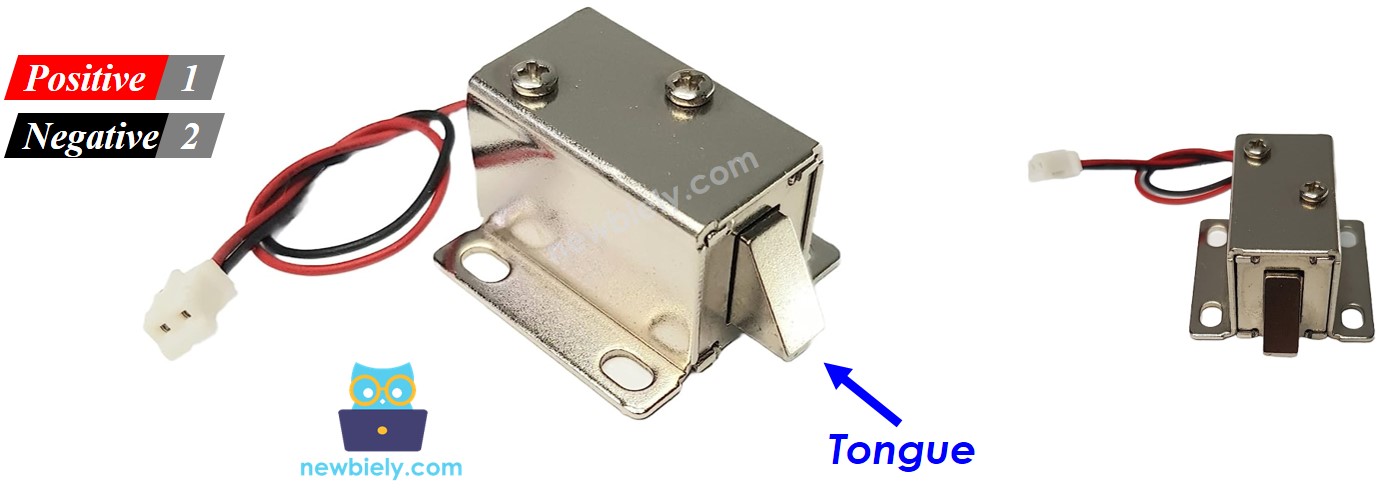
The solenoid lock has two wires:
Power Connections:
- Red wire (+): Positive terminal
- Connect to +12V from DC power supply
- Do NOT connect directly to Arduino (insufficient current)
- Must use relay for switching
- Black wire (-): Negative terminal (Ground)
- Connect to GND of DC power supply
- Common ground with Arduino
- Locked (Powered):
- 12V applied to solenoid
- Electromagnetic coil energized
- Metal bolt extends outward
- Door/cabinet secured
- Unlocked (Unpowered):
- No voltage applied
- Spring returns bolt inward
- Door/cabinet released
- Arduino sends LOW signal (relay off) → Solenoid unpowered → Unlocked
- Arduino sends HIGH signal (relay on) → Solenoid powered → Locked
- Arduino controls timing and access conditions in code
Important Voltage/Current Requirements:
How It Works
Operation States:
Relay Control Logic:
Since solenoid locks require 12V and Arduino provides only 3.3V, we use a relay as an electrically controlled switch:
Control Flow:
Learn More:
For detailed relay operation, see Arduino MKR WiFi 1010 - Relay tutorial.
Wiring Diagram
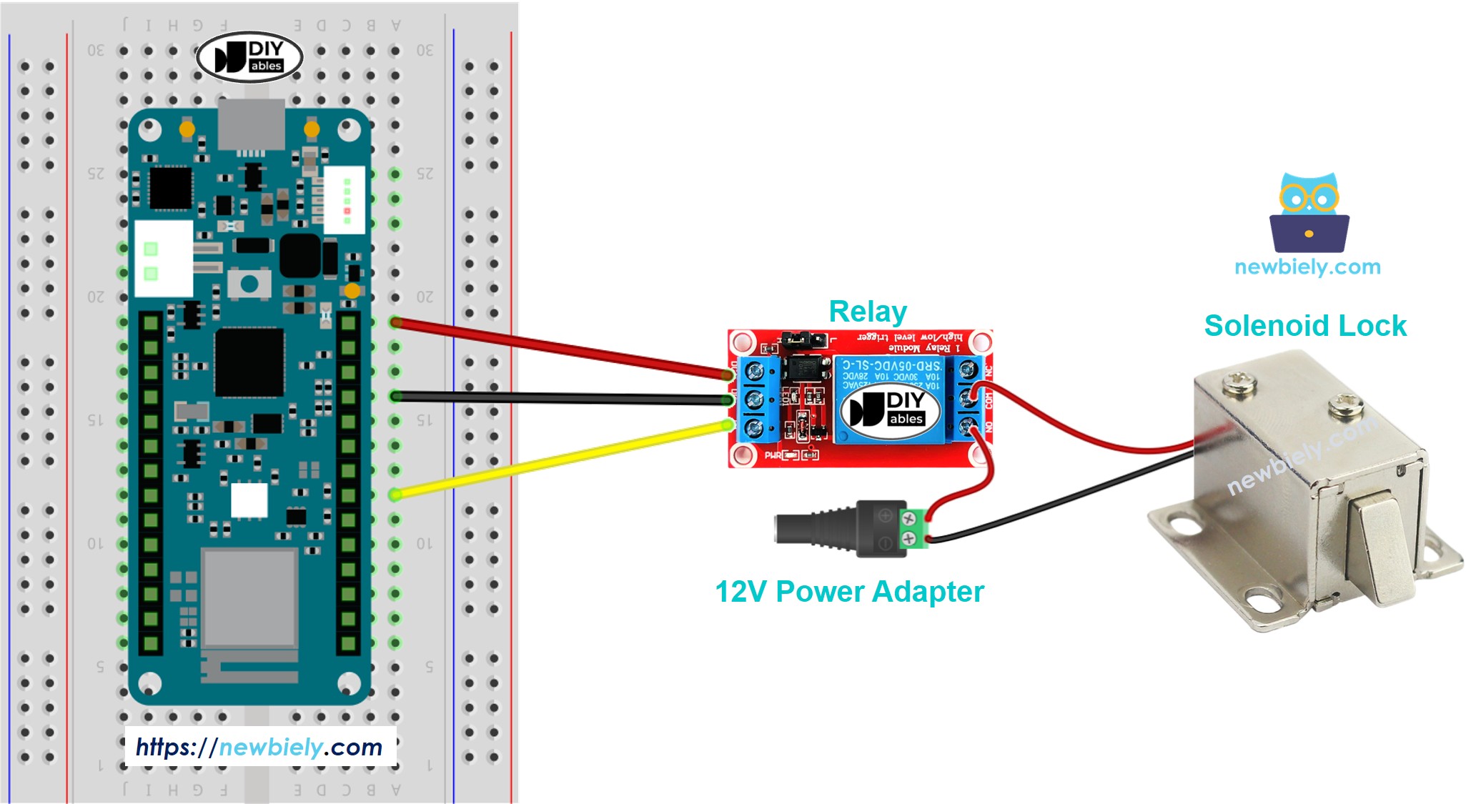
This image is created using Fritzing. Click to enlarge image
Detailed Connections
Solenoid Lock Wiring:
- Solenoid Red (+) → Relay COM (Common)
- Connect to relay's normally open contact
- Solenoid Black (-) → 12V Supply GND
- Common ground with Arduino and power supply
- Relay NO (Normally Open) → 12V Supply +
- Power source when relay closes
- Relay VCC → Arduino 5V
- Powers relay coil circuitry
- Relay GND → Arduino GND
- Common ground
- Relay IN → Arduino Digital Pin (e.g., D2)
- Control signal from Arduino
- USB power for Arduino (programming and logic)
- 12V DC adapter for solenoid lock (high current device)
- Never connect solenoid directly to Arduino pins
- Relay isolates Arduino from high-voltage/current circuit
- Use properly rated 12V power supply (1A minimum)
- Check polarity before connecting
Relay Module Connections:
Power Supply:
For This Project: You need TWO power sources:
Common ground connection required between both supplies.
Safety Notes:
Arduino MKR WiFi 1010 Code
This code demonstrates automatic lock/unlock cycling - locks for 5 seconds, then unlocks for 5 seconds.
Code Explanation
Pin Definition:
Defines which Arduino pin controls the relay.
Lock Control:
HIGH = Relay closes → 12V to solenoid → Locked
LOW = Relay opens → No power → Unlocked
Detailed Instructions
New to Arduino MKR WiFi 1010? Complete our Getting Started with Arduino MKR WiFi 1010 tutorial first to set up your development environment.
Step 1: Hardware Setup
- Connect relay to Arduino (VCC to 5V, GND to GND, IN to D2)
- Connect solenoid lock to relay and 12V supply following wiring diagram
- Ensure common ground between Arduino and 12V supply
- Connect Arduino to computer via USB
- Connect 12V power adapter
Step 2: Upload Code
- Copy code above into Arduino IDE
- Select Arduino MKR WiFi 1010 board and COM port
- Click Upload button
Step 3: Test Operation
- Observe solenoid bolt extending (locked)
- Wait 5 seconds
- Observe bolt retracting (unlocked)
- Cycle repeats automatically
Safety Testing:
- Listen for clicking sound from relay
- Check solenoid bolt movement is smooth
- Verify lock holds firmly when engaged
- Ensure unlock releases completely
Troubleshooting Common Issues
Problem: Solenoid Doesn't Lock or Unlock
Possible Causes:
- No 12V power to solenoid
- Relay not switching
- Wiring error
- Insufficient current from power supply
Solutions:
- Check 12V supply: Use multimeter to verify voltage
- Test relay: Listen for click sound when Arduino sends signal
- Verify wiring:
- Solenoid Red → Relay COM
- Relay NO → 12V+
- Solenoid Black → GND
- Check power supply rating: Must provide at least 500mA
- Test relay independently: Manually trigger with jumper wire
Problem: Relay Clicks But Solenoid Doesn't Move
Possible Causes:
- Solenoid damaged
- Insufficient voltage
- Mechanical obstruction
Solutions:
- Test solenoid directly: Connect briefly to 12V (bypass relay)
- Measure voltage at solenoid: Should be 12V when relay on
- Check for binding: Ensure bolt moves freely
- Inspect solenoid: Look for physical damage
Problem: Weak Locking Force
Cause: Voltage drop or insufficient current.
Solutions:
- Use shorter, thicker wires to 12V supply
- Check power supply can deliver rated current
- Measure voltage at solenoid terminals under load
Problem: Solenoid Gets Hot
Cause: Normal for continuous operation, but excessive heat indicates problem.
Solutions:
- Check voltage: Verify 12V, not higher
- Reduce duty cycle: Don't keep locked 100% of time if not needed
- Add cooling: Ensure airflow around solenoid
- Check current draw: Should be within spec (200-500mA)
Problem: Relay Module LED On But Relay Not Switching
Cause: Some relay modules are active-LOW triggered.
Solution: Invert logic in code:
Challenge Yourself - Creative Extensions
Once you have basic solenoid lock control working, try these enhancements:
1. Keypad Access Control
Unlock with PIN code:
2. RFID Card Access
Use RFID reader for keyless entry:
3. Remote WiFi Control
Unlock via web interface:
4. Timed Auto-Lock
Automatically re-lock after timeout:
5. Door Sensor Integration
Detect if door actually closed:
6. Access Log
Record all lock/unlock events:
7. Multiple Lock System
Control several locks independently:
8. Battery Backup Detection
Alert when power fails:
9. Scheduled Access
Allow entry only during specific times:
10. Buzzer Feedback
Audio confirmation of lock state:
Experiment with electronic locks and build smart access control systems!