Arduino MKR WiFi 1010 - Electromagnetic Lock
Learn how to control an electromagnetic lock (also called magnetic lock, maglock, or EM lock) with the Arduino MKR WiFi 1010 to create secure access control systems for doors, cabinets, gates, and automated entry points. Electromagnetic locks are essential components for building smart door systems, office security, apartment entry control, cabinet locking mechanisms, automatic gates, server room access, storage lockers, museum display cases, and IoT security projects. In this comprehensive tutorial, you'll discover how to connect an electromagnetic lock to your Arduino MKR WiFi 1010 board through a relay module, understand the difference between electromagnetic locks and solenoid locks, control high-power locks safely with relay isolation, program lock and unlock sequences with proper timing, implement fail-safe vs fail-secure configurations, integrate with buttons, keypads, and RFID systems, and create intelligent access control logic. This guide includes complete wiring diagrams for Arduino MKR WiFi 1010 electromagnetic lock connections with relay control, working example code with detailed explanations, power supply recommendations for 12V/24V electromagnetic locks, troubleshooting tips for magnetic holding force and relay control issues, and 10 creative challenge projects to expand your Arduino MKR WiFi 1010 electromagnetic lock applications. Whether you're building a smart door lock, automated access control system, security cabinet, or magnetic entry gate with your Arduino MKR WiFi 1010, this tutorial provides everything you need to work with electromagnetic locks safely and effectively.
Hardware Preparation
| 1 | × | Arduino MKR WiFi 1010 | |
| 1 | × | Micro USB Cable | |
| 1 | × | Electromagnetic Lock | |
| 1 | × | Relay | |
| 1 | × | 12V Power Adapter | |
| 1 | × | Optionally, DC Power Jack | |
| 1 | × | Breadboard | |
| 1 | × | Jumper Wires |
Or you can buy the following kits:
| 1 | × | DIYables Sensor Kit (18 sensors/displays) |
Additionally, some of these links are for products from our own brand, DIYables .
Overview of Electromagnetic Lock
An electromagnetic lock (maglock) uses electromagnetic force to secure doors and entry points. When electricity flows through the electromagnet coil, it creates a powerful magnetic field that holds the metal armature plate with significant force - typically ranging from 280 kg (600 lbs) to over 550 kg (1200 lbs) of holding force. Unlike mechanical locks with moving parts, electromagnetic locks have no latches, bolts, or cylinders, making them extremely reliable and resistant to picking or tampering. They're commonly used in commercial buildings, access control systems, and high-security areas where fail-safe operation is required (lock releases when power is lost for emergency exit).
Electromagnetic Lock vs Solenoid Lock
| Feature | Electromagnetic Lock | Solenoid Lock |
|---|---|---|
| Operation Principle | Magnetic attraction force | Mechanical bolt movement |
| Holding Force | Very high (280-550+ kg) | Lower (up to 100 kg) |
| Moving Parts | None (except armature alignment) | Moving bolt/latch mechanism |
| Durability | Extremely high (no wear) | Moderate (mechanical wear) |
| Failure Mode | Fail-safe (unlocks on power loss) | Fail-secure (stays locked) |
| Installation | Surface mount, needs alignment | Requires door frame drilling |
| Noise Level | Silent operation | Audible clicking sound |
| Power Consumption | Continuous (while locked) | Momentary pulse to actuate |
| Typical Voltage | 12V DC or 24V DC | 12V DC |
| Best Use Case | Emergency exit doors, offices | Cabinets, drawers, gates |
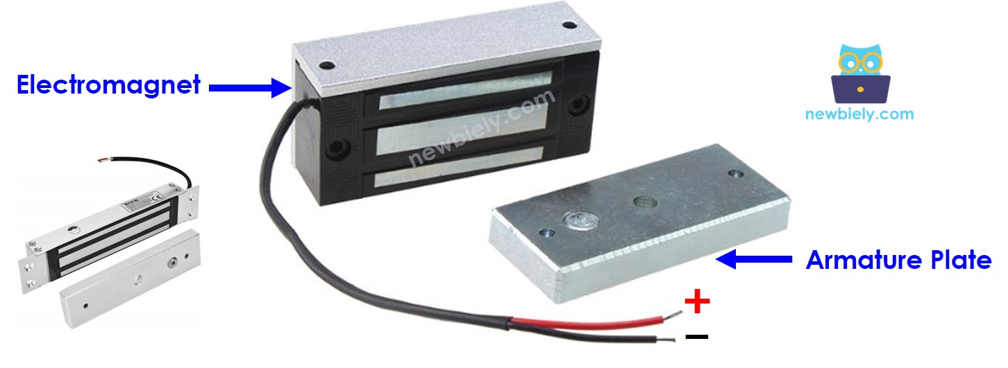
Electromagnetic Lock Pinout
The electromagnetic lock consists of two main components:
- Armature plate: Metal plate attached to the moving door/gate section. Contains ferromagnetic material that responds to magnetic fields.
- Electromagnet: Mounted on the fixed door frame. Has two wire terminals (red positive, black negative) that connect to DC power supply.
When the door is closed, the armature plate and electromagnet surfaces make full contact for maximum holding force.
How Electromagnetic Lock Works
Electromagnetic locks operate on the principle of electromagnetism:
LOCKED STATE (Power Applied):
- Arduino MKR WiFi 1010 pin is set HIGH (3.3V)
- This activates the relay module
- Relay switches ON and connects 12V DC power to the electromagnet
- Electric current flows through the electromagnet coil, creating a strong magnetic field
- The magnetic field generates attractive force (280-550 kg)
- Armature plate is pulled tightly against the electromagnet
- Door is securely LOCKED and cannot be opened
UNLOCKED STATE (Power Removed):
- Arduino MKR WiFi 1010 pin is set LOW (0V)
- This deactivates the relay module
- Relay switches OFF and disconnects power from the electromagnet
- No current flows through the electromagnet coil
- Magnetic field collapses immediately
- No attractive force between electromagnet and armature plate
- Door is free to open - UNLOCKED state
Why Use a Relay?
- Electromagnetic locks require high voltage (12V DC) and high current (500mA-1A)
- Arduino MKR WiFi 1010 pins can only provide 3.3V at 7mA maximum
- Direct connection would damage the Arduino board
- Relay acts as an electrical switch controlled by low-power Arduino signal
- Relay safely controls high-power electromagnet circuit
Control Logic with Arduino MKR WiFi 1010:
Electromagnetic locks require high voltage (12V or 24V DC) and high current (500mA to 1A), which exceeds the Arduino MKR WiFi 1010's pin capabilities (3.3V, 7mA maximum). Therefore, we use a relay module as an electrical switch:
- Arduino Pin LOW (0V) Relay OFF No power to electromagnet Door UNLOCKED
- Arduino Pin HIGH (3.3V) Relay ON 12V power to electromagnet Door LOCKED
The relay provides electrical isolation between the Arduino MKR WiFi 1010's low-power control circuit and the electromagnetic lock's high-power circuit, protecting your board from damage. Check out the Arduino MKR WiFi 1010 Relay tutorial for detailed relay operation principles.
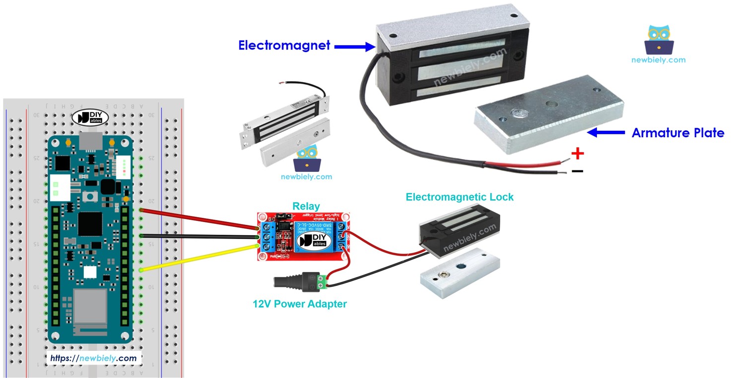
Wiring Diagram
This image is created using Fritzing. Click to enlarge image.
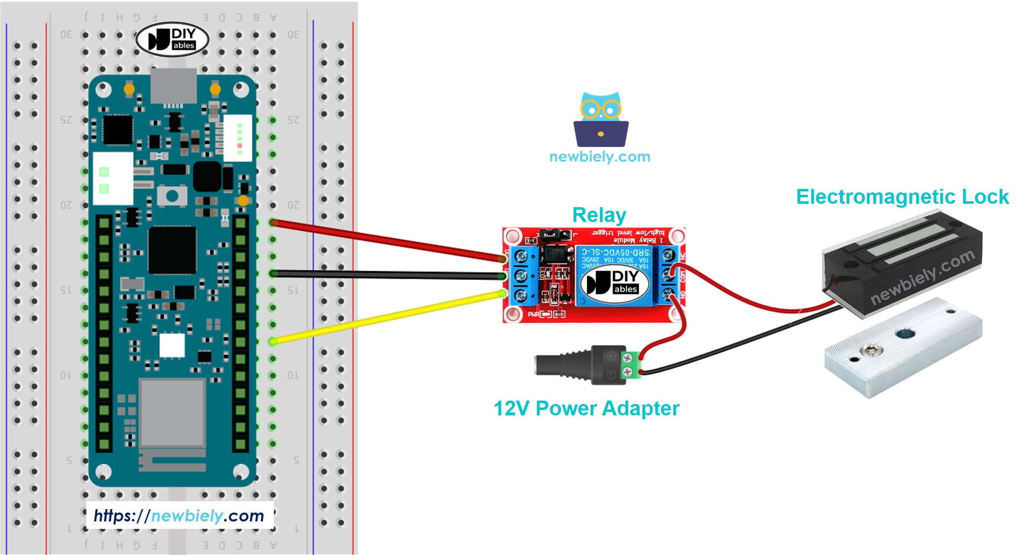
This image is created using Fritzing. Click to enlarge image
If you're unfamiliar with how to supply power to the Arduino MKR WiFi 1010 and other components, please refer to the Arduino MKR WiFi 1010 - How to Power tutorial for detailed instructions.
Wiring Instructions:
| Arduino MKR WiFi 1010 | Relay Module | 12V Power Supply | Electromagnetic Lock |
|---|---|---|---|
| Pin 2 | IN | ||
| GND | GND | ||
| VCC | (not used) | ||
| COM | (+) Positive | ||
| NO | (+) Red Wire | ||
| NC (don't use) | |||
| (-) Negative | (-) Black Wire |
Important Wiring Notes:
- Connect relay VCC to 5V if your relay module requires 5V (most relay modules have onboard voltage regulators)
- Some relay modules can work with 3.3V signal - check your relay specifications
- The electromagnetic lock typically comes with red (+) and black (-) wires
- CRITICAL: Never connect the electromagnetic lock directly to Arduino pins - always use a relay
- Use a 12V DC power adapter rated for at least 1A (check your electromagnetic lock specifications)
- Keep high-power wires (12V supply, lock wires) separated from Arduino signal wires
- Ensure all ground connections are secure for proper relay operation
Arduino MKR WiFi 1010 Code
The code below locks and unlocks the door every five seconds.
Detailed Instructions
New to Arduino MKR WiFi 1010? Complete our Getting Started with Arduino MKR WiFi 1010 tutorial first to set up your development environment.
Follow these steps to control your electromagnetic lock:
- Wire the components according to the wiring diagram above. Double-check all connections:
- Arduino Pin 2 to Relay IN
- Arduino GND to Relay GND
- 12V Power (+) to Relay COM
- Relay NO to Electromagnetic Lock (+) red wire
- 12V Power (-) to Electromagnetic Lock (-) black wire
- Connect the 12V power adapter to your relay circuit (do NOT connect to Arduino)
- Mount the electromagnetic lock on a fixed surface (door frame)
- Position the armature plate on the moving part (door) so it aligns with the electromagnet when closed
- Plug your Arduino MKR WiFi 1010 into your computer's USB port
- Launch the Arduino IDE on your computer
- Select the correct board and port:
- Go to Tools → Board → Arduino SAMD Boards → Arduino MKR WiFi 1010
- Go to Tools → Port and select your Arduino's COM port
- Copy the code provided above
- Paste it into the Arduino IDE
- Click the Upload button (right arrow icon) to compile and upload the code
- Wait for the upload to complete - you'll see "Done uploading" when finished
- Open the Serial Monitor by clicking the magnifying glass icon (top-right) or pressing Ctrl+Shift+M
- Set the baud rate to 9600 in the Serial Monitor dropdown
- Observe the behavior:
- Bring the armature plate close to the electromagnet surface
- You should hear a click from the relay when it switches
- The electromagnet will pull and hold the armature plate firmly (locked state)
- After 5 seconds, the relay clicks again and the armature plate releases (unlocked state)
- The cycle repeats automatically every 5 seconds
- You should feel strong magnetic attraction when the lock is engaged (locked state)
- The armature plate should be difficult to pull away when locked (280-550 kg holding force)
- The lock should release immediately when unlocked (no holding force)
- If the lock doesn't hold well, ensure surfaces are clean and making full contact
- Check the Serial Monitor to verify the lock/unlock sequence timing
Result on Serial Monitor
You should see output similar to this in the Serial Monitor:
Testing Tips:
Troubleshooting
Here are solutions to common issues when working with electromagnetic locks and Arduino MKR WiFi 1010:
Problem 1: Lock Doesn't Hold at All
Symptoms: Door can be opened easily even when system shows "locked" state.
Possible Causes:
- Insufficient power supply to electromagnet
- Poor contact between armature plate and electromagnet
- Relay not switching properly
- Wrong polarity connection (though DC electromagnets usually work either way)
Solution:
Check:
- Measure voltage at electromagnet terminals when locked (should be 12V)
- Verify relay LED indicator turns on/off with Arduino commands
- Ensure armature plate and electromagnet surfaces are clean and flat
- Check power supply can deliver sufficient current (500mA-1A)
Problem 2: Lock Works Initially, Then Fails
Symptoms: Lock holds for a few seconds then releases, or works once then stops.
Possible Causes:
- Power supply overheating or insufficient capacity
- Relay contacts overheating due to high current
- Electromagnet overheating causing thermal shutdown
- Loose wiring connections
Solution: Use proper rated components and add status monitoring:
Verify:
- Power supply rated for at least 1.5x the electromagnet's current draw
- Relay rated for lock's voltage and current (use 10A relay minimum)
- Adequate ventilation for lock, relay, and power supply
Problem 3: Relay Clicks But Lock Doesn't Engage
Symptoms: You hear the relay switching, but electromagnet has no holding force.
Possible Causes:
- Lock connected to wrong relay terminals (use COM and NO)
- Power supply connected incorrectly through relay
- Blown relay contacts
- Lock wiring disconnected
Solution: Verify wiring carefully:
Double-check:
- Lock positive wire connects to relay NO (Normally Open) terminal
- Power positive connects to relay COM (Common) terminal
- Lock negative connects directly to power supply negative
- Never use NC (Normally Closed) terminal unless you want reversed logic
Problem 4: Arduino Resets When Lock Activates
Symptoms: Arduino MKR WiFi 1010 restarts or freezes when relay switches on.
Possible Causes:
- Insufficient power supply to Arduino
- Electrical noise from relay coil back-EMF
- Shared ground causing voltage spikes
- Power supply voltage drop when lock engages
Solution: Improve power isolation and filtering:
Improvement checklist:
- Use separate power supplies for Arduino (USB) and electromagnet (12V adapter)
- Never share power between Arduino and high-power electromagnet
- Add flyback diode across relay coil if using bare relay module
- Use optoisolated relay modules for better isolation
- Keep Arduino and high-power wires separated
Problem 5: Lock Doesn't Release Immediately
Symptoms: Door stays locked for 1-2 seconds after unlock command.
Possible Causes:
- Residual magnetism in electromagnet core
- Relay slow to switch off
- Mechanical binding between armature and electromagnet
Solution: This is usually normal behavior. Add status indication:
Problem 6: Lock Hums or Buzzes When Engaged
Symptoms: Audible humming noise from electromagnet when locked.
Possible Causes:
- AC voltage applied instead of DC
- Poor quality DC power supply with ripple
- Loose mounting causing vibration
Solution:
- Verify you're using DC power supply (12V DC, not 12V AC)
- Use filtered/regulated power supply
- Tighten all mounting screws
- Add rubber washers to reduce vibration transmission
Electromagnetic locks should operate silently. Any buzzing indicates power quality issues.
Challenge Extensions
Once you've mastered basic electromagnetic lock control with Arduino MKR WiFi 1010, try these creative projects:
Challenge 1: Button-Controlled Door Lock
Add a push button to lock/unlock the door manually:
Challenge 2: Keypad Access Control System
Use a 4x4 keypad for password-protected entry:
Challenge 3: RFID Card Access System
Use RFID reader for contactless entry:
Challenge 4: WiFi Remote Door Control
Control the lock via web interface over WiFi:
Challenge 5: Door Open Detection with Sensor
Add magnetic door sensor to detect forced entry:
Challenge 6: Scheduled Lock/Unlock Times
Automatic locking schedule using RTC module:
Challenge 7: Multi-Lock System Control
Control multiple doors from one Arduino:
Challenge 8: Entry Log with SD Card
Log all lock/unlock events with timestamps:
Challenge 9: Fingerprint Scanner Access
Use biometric fingerprint sensor for secure access:
Challenge 10: Emergency Override System
Add emergency unlock button with LED indicators: