
Arduino Giga R1 WiFi SW520D Tilt Sensor
This guide covers tilt detection with the Arduino Giga R1 WiFi — from hardware setup to working code. The SW520D is a compact electromechanical tilt sensor that uses a conductive metal ball inside a cylindrical housing to detect orientation changes. When the module tilts beyond a threshold angle, the ball rolls away from the electrical contacts, breaking the circuit and changing the digital output state.
The Arduino Giga R1 WiFi's dual-core STM32H747XI processor and generous memory make it an excellent platform for tilt-based applications that require real-time processing and responsive triggering. This tutorial walks through the complete implementation of SW520D tilt detection, demonstrating how to leverage the board's GPIO capabilities for reliable orientation sensing.
Tilt sensors find widespread application in industrial automation (equipment positioning and anti-tip protection), security systems (tamper detection for enclosures), robotics (balance and orientation feedback), consumer electronics (display rotation and gesture detection), and IoT deployments (remote asset monitoring). The combination of the Arduino Giga R1 WiFi's processing power and the SW520D's robust mechanical design enables dependable tilt-reactive systems for both prototyping and production environments.
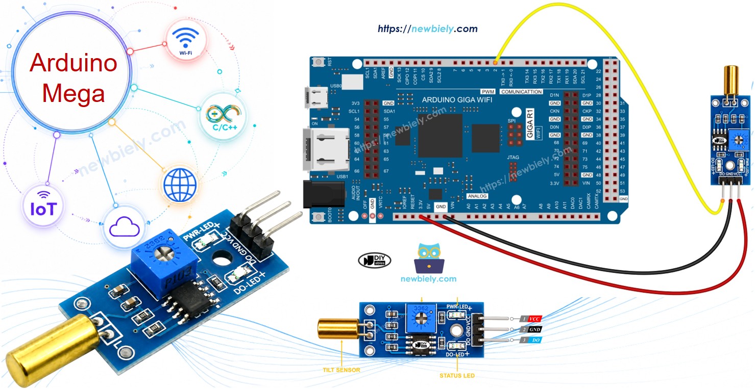
Hardware Preparation
Or you can buy the following kits:
| 1 | × | DIYables Sensor Kit (18 sensors/displays) |
Additionally, some of these links are for products from our own brand, DIYables .
Overview of SW520D Tilt Sensor
The SW520D is an electromechanical tilt sensor based on a conductive ball switch mechanism. A small metallic ball is free to roll within a cylindrical housing. When the housing is oriented within the normal operating range, the ball rests against two electrical contacts at the base, completing the circuit. When the housing is tilted beyond the switching threshold (approximately 10–45° depending on mounting orientation), the ball rolls away from the contacts, opening the circuit.
The SW520D module integrates this switch element with signal conditioning circuitry to provide a clean TTL-compatible digital output suitable for direct connection to microcontroller GPIO pins. Unlike analog sensors, no ADC resources are required — detection is entirely digital, simplifying firmware implementation.
Key specifications include operating voltage from 3.3V to 5V, output current up to 20mA, response time under 5ms, operating temperature from -20°C to +85°C, and mechanical lifetime exceeding 100,000 switching cycles. These characteristics make it suitable for both indoor and light industrial deployment.
The SW520D Tilt Sensor Pinout
The pinout defines the electrical interface between the SW520D module and the Arduino Giga R1 WiFi. Correct wiring is essential — an incorrect connection may damage the module's output circuitry or produce unreliable detection behavior.
- VCC pin: Power input, 3.3V to 5V DC. Connects to the Arduino 5V or 3.3V rail to supply the output driver circuit. Current consumption: 2–5mA typical.
- GND pin: Ground reference, 0V. Connects to the Arduino ground plane to complete the power circuit and establish signal reference level.
- DO pin: Digital output, TTL compatible (0V/3.3V or 0V/5V depending on supply voltage). Outputs HIGH when the sensor is upright (ball closing the contact) and LOW when the sensor is tilted (ball rolling away from contacts). Connects to any Arduino digital input pin.
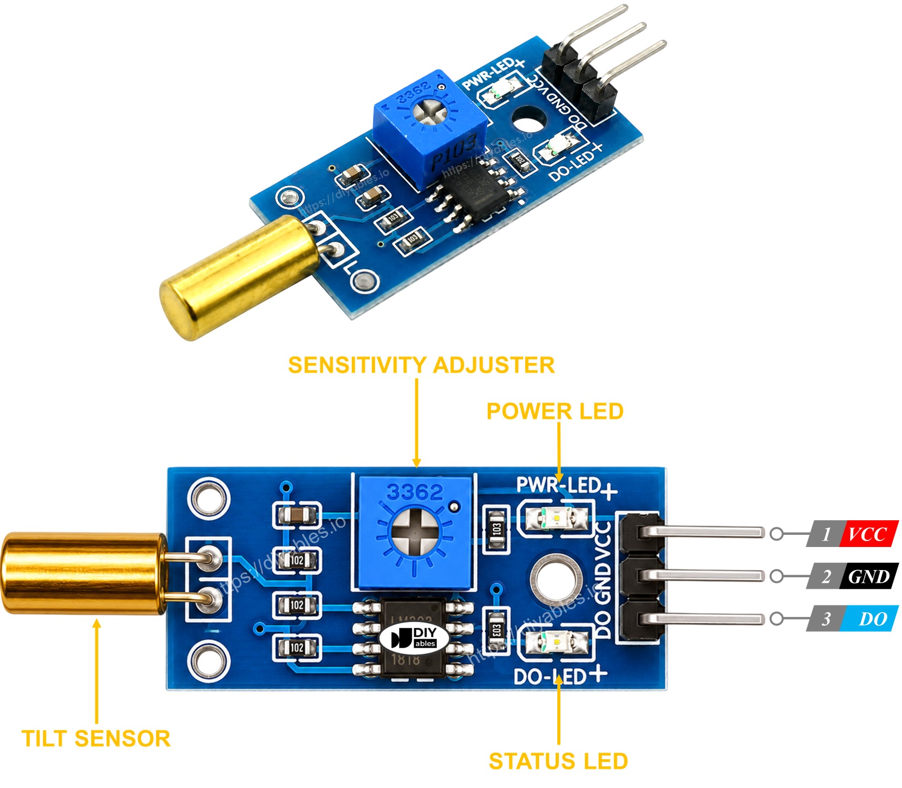
The dual LED indicators provide immediate visual feedback during installation and testing: the power LED confirms proper supply voltage, while the detection LED mirrors the digital output state for quick orientation verification without requiring a serial connection.
Electrical Note: For deployments in electrically noisy environments or with long wiring runs, consider adding a 10kΩ pull-up resistor between the DO pin and VCC to strengthen the logic-high signal level and improve noise immunity.
How It Works
The SW520D operates through a purely mechanical switching action with no active electronics in the sensing element itself. The module's output circuitry translates the switch state into a logic-level digital signal:
- When the sensor is upright, the metal ball rests against the electrical contacts, completing the circuit, and the output pin outputs HIGH.
- When the sensor is tilted beyond the threshold angle, the metal ball rolls away from the contacts, breaking the circuit, and the output pin switches to LOW.
This design provides inherently clean digital transitions without the threshold calibration requirements of analog sensors. However, because the ball can briefly bounce when transitioning states, debouncing logic in firmware may be required for applications that count tilt events rather than simply detect the current state.
Wiring Diagram
The following implementation demonstrates direct GPIO interfacing between the Arduino Giga R1 WiFi and the SW520D tilt sensor. The connection utilizes the board's 5V supply rail and digital input capabilities for reliable tilt detection with minimal external components.
| SW520D Tilt Sensor Pin | Arduino Giga R1 WiFi Pin |
|---|---|
| VCC | 5V |
| GND | GND |
| DO | Digital Pin 2 |
Digital pin 2 provides interrupt capability (external interrupt 0) for future expansion to interrupt-driven tilt detection, reducing CPU overhead compared to continuous polling methods. The Arduino Giga R1 WiFi's robust GPIO drivers can handle the sensor's output current requirements without additional buffering.
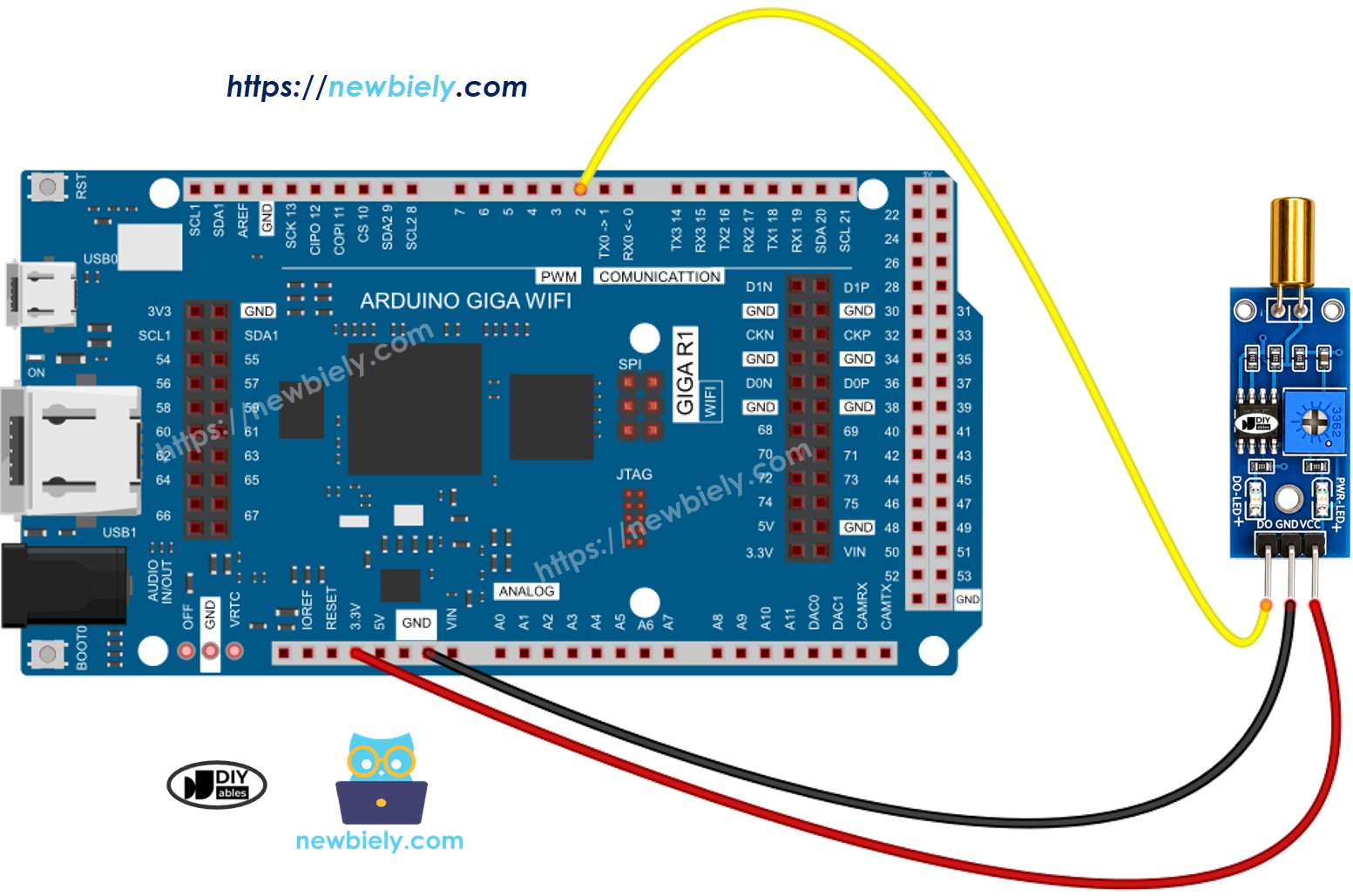
This image is created using Fritzing. Click to enlarge image
How To Program For SW520D Tilt Sensor
The implementation logic centers on GPIO configuration and digital state polling. The Arduino Giga R1 WiFi's STM32H747XI processor provides fast GPIO access and flexible pin configuration, enabling responsive tilt detection with minimal latency.
Initialize the selected Arduino pin as a digital input to enable reading of the sensor's output state. The pinMode() function configures the GPIO direction:
Read the instantaneous digital state using digitalRead() to determine current tilt detection status. This function returns the logical level present on the specified pin:
The returned value is HIGH when the sensor is upright and LOW when tilted, following the sensor's active-low tilt output logic. For applications requiring edge detection or event counting, store previous readings and compare against current values to identify tilt onset and return events.
Arduino Code - Detecting the tilt
Detailed Instructions
Prerequisites: Arduino IDE installed and the Giga R1 WiFi board package configured. Refer to the Getting Started guide for setup instructions.
- Upload Code: Open the provided code in Arduino IDE and click the Upload button. Verify successful compilation and upload completion through the IDE's status messages.
- Connect Hardware: Wire the SW520D tilt sensor according to the diagram above. Verify VCC connection shows power LED illumination on the sensor module.
- Test Detection: Open Serial Monitor (Tools → Serial Monitor) and set baud rate to 9600. Tilt the sensor back and forth — orientation changes should trigger detection messages.
- Verify Operation: Confirm the detection LED mirrors serial output behavior. When the sensor is upright, the LED should be on; when tilted, the LED should be off.
- Fine-tune Mounting: Adjust the physical mounting angle of the sensor to achieve the desired tilt threshold for your application.
Technical Note: The Arduino Giga R1 WiFi's dual-core architecture enables real-time tilt processing extensions. Consider implementing interrupt-driven detection on one core while maintaining WiFi communication or data logging functions on the other core for advanced applications.
Serial Monitor Output
Now we can customize the code to activate an LED or a light when a tilt is detected, or even make a servo motor rotate. You can find more information and step-by-step instructions in the tutorials provided at the end of this tutorial.
Application Ideas
Industrial Equipment Protection: Implement tilt monitoring for machinery and equipment to detect unsafe operating angles or unauthorized movement. The Arduino Giga R1 WiFi's WiFi capability enables real-time alerts to operations management systems, while the dual-core architecture ensures detection response is not interrupted by communication tasks.
Security and Tamper Detection: Deploy tilt sensors inside enclosures to detect physical tampering or unauthorized access. The SW520D's robust mechanical design provides reliable switching across thousands of actuation cycles, making it suitable for long-term security deployments with minimal maintenance requirements.
Robotics and Balance Control: Integrate tilt detection into robotic platforms for basic orientation feedback and stability monitoring. The Arduino Giga R1 WiFi's processing power enables real-time control loop implementation, while the board's extensive GPIO complement supports simultaneous integration of additional sensors and actuators.
Troubleshooting
If you encounter any issues with the SW520D tilt sensor's functionality, please consider the following troubleshooting steps:
- Check the orientation: The SW520D is sensitive to its mounting orientation. Make sure it is installed in the correct upright position for reliable detection. Small adjustments to the mounting angle can significantly affect the switching threshold.
- Reduce vibrations: Mechanical vibrations can cause the ball to bounce between states. To minimize false triggers, try mounting the sensor on a stable, vibration-dampened surface.
- Check the wiring: Verify that the VCC, GND, and DO pins are connected correctly and that all connections are secure.
- Check the power supply: Ensure that the power supply is clean and stable for consistent readings.