
Arduino MicroPython BTS7960 Motor Driver
A big 12V cooling fan is great on a hot day, but at full speed it is loud, and its motor needs far more current than any pin can give. Speed control fixes the noise, and the DIYables BTS7960 43A Motor Driver Module takes care of the current. The Arduino Giga R1 WiFi only sends small 3.3V signals to the module, and the module switches the heavy 12V current for the motor. So a short MicroPython script can choose a soft breeze, a full blast, or anything in between. On this page, a 12V DC motor plays the part of the fan, and Thonny shows each step of the test. You will see:
- What the eight pins of the control header and the four screw terminals do.
- How to wire the module to the Giga: RPWM to D9, LPWM to D10, R_EN to D12, L_EN to D11, plus 5V and GND.
- How duty_u16() sets the speed, and how RPWM and LPWM choose the direction.
- How a brake (fast stop) and a coast (slow roll) look different, both in one script.
Hardware Preparation
Or you can buy the following kits:
| 1 | × | DIYables Sensor Kit (18 sensors/displays) |
Additionally, some of these links are for products from our own brand, DIYables .
Overview of BTS7960 Motor Driver and Pinout
Small driver boards such as the L298N or the DRV8833 are fine for toy motors. A large gear motor, a wiper motor, a winch or the motor of a big fan needs a much stronger driver, and the BTS7960 module is made for this job. You may also find the same board sold as "IBT-2" or "HW-039". It carries two Infineon BTS7960B chips. One chip makes one half-bridge; together they form a full H-bridge. In short: one brushed DC motor, in both directions, with its speed set by PWM.
How does it work? Each half-bridge holds one wire of the motor and can connect that wire to B+ or to B-. When one side goes to B+ and the other side stays on B-, current flows through the motor, and the motor turns. When the two sides swap, the current flows the other way, and so does the motor. PWM turns the active side on and off very fast. The longer the ON part of each pulse, the more power the motor gets, and the faster it spins.
| Item | DIYables BTS7960 43A Motor Driver Module |
|---|---|
| Power chips | 2 x Infineon BTS7960B half-bridge (together one H-bridge) |
| Motor | 1 brushed DC motor, forward and reverse |
| Motor supply on B+ and B- | 5.5V to 27V DC (6V, 12V or 24V systems) |
| Current | up to 43A (the current limit of the chip, a peak value) |
| PWM on RPWM and LPWM | up to 25 kHz |
| Logic side | 74HC14 buffer chip, powered by the VCC pin |
| Protection | current limiting, over-temperature protection |
| Control header | 2 x 4 male pins |
Read the 43A with care. It is the level where the chip starts to limit the current, not a value for long use. For a motor that runs for minutes or hours, stay far below it. For long runs, what counts is how well the big heat sink under the board can shed heat.
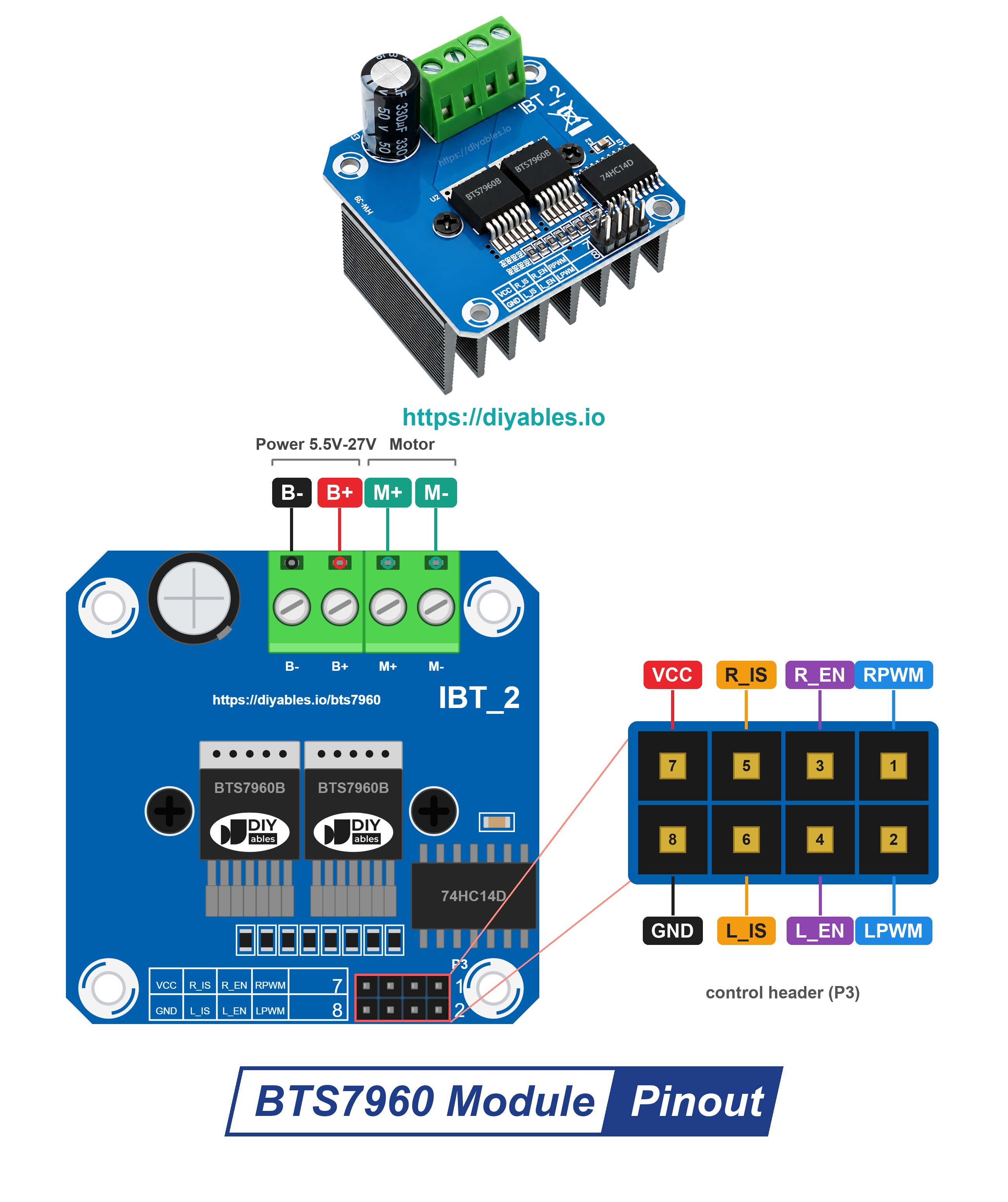
The control header has two rows of four pins. The names are printed next to the pins, but the board writes R_IS and L_IS as "R_S" and "L_S":
| Row | Pin 7 and 8 | Pin 5 and 6 | Pin 3 and 4 | Pin 1 and 2 |
|---|---|---|---|---|
| Top row (odd pins) | VCC | R_IS | R_EN | RPWM |
| Bottom row (even pins) | GND | L_IS | L_EN | LPWM |
What each pin does, and where it goes on the Giga:
- RPWM: the speed input for the forward direction (right half-bridge). A PWM signal here turns the motor forward. Wire it to D9.
- LPWM: the speed input for the reverse direction (left half-bridge). Wire it to D10.
- R_EN: switches the right half-bridge on when it is HIGH. Wire it to D12.
- L_EN: switches the left half-bridge on when it is HIGH. Wire it to D11.
- R_IS and L_IS: current-sense and fault outputs. This tutorial does not use them, so leave them free.
- VCC: feeds the small 74HC14 buffer chip and the power LED; motor current never flows through it. Wire it to the 5V pin of the Giga.
- GND: the logic ground. Wire it to a GND pin of the Giga.
- B+ and B- (screw terminal): the motor supply. B+ takes the + of the 12V adapter, and B- takes the -.
- M+ and M- (screw terminal): the two wires of the motor.
Moving the Motor With Four Signals
With R_EN and L_EN both HIGH, the two PWM pins decide what happens. In MicroPython, you set the PWM level with duty_u16(), from 0 (always LOW) to 65535 (always HIGH):
| RPWM | LPWM | Result |
|---|---|---|
| duty 1 to 65535 | 0 | forward, faster with a bigger duty |
| 0 | duty 1 to 65535 | reverse, faster with a bigger duty |
| 0 | 0 | brake, the driver joins the two motor wires and the motor stops fast |
Now set R_EN and L_EN LOW. Both half-bridges switch off, the motor gets no power, and it coasts: it rolls to a stop on its own. Keep one simple rule in your code: at least one of RPWM and LPWM must be 0. Never give PWM to both of them at the same time.
Power and Ground
- VCC goes to the 5V pin of the Giga. It only powers the small buffer chip, and the maker of the module asks for 5V there. The control pins are fine with 3.3V signals, so the Giga pins can drive them straight. These inputs have pull-down resistors, so no 5V flows back into the Giga.
- On the module, GND and B- are the same point. So the single GND wire from the Giga also gives a common ground with the 12V adapter. So you do not need a second ground wire.
- The 12V on B+ must never reach the Giga. The Giga gets its power from the USB cable, and the motor gets its power from the adapter.
Wiring Diagram
Six jumper wires join the Giga to the control header. The four signal wires go to the digital pins D9 to D12. The VCC wire goes to the 5V pin, and the GND wire can use any GND pin of the Giga. The 12V side uses only the screw terminals of the module.
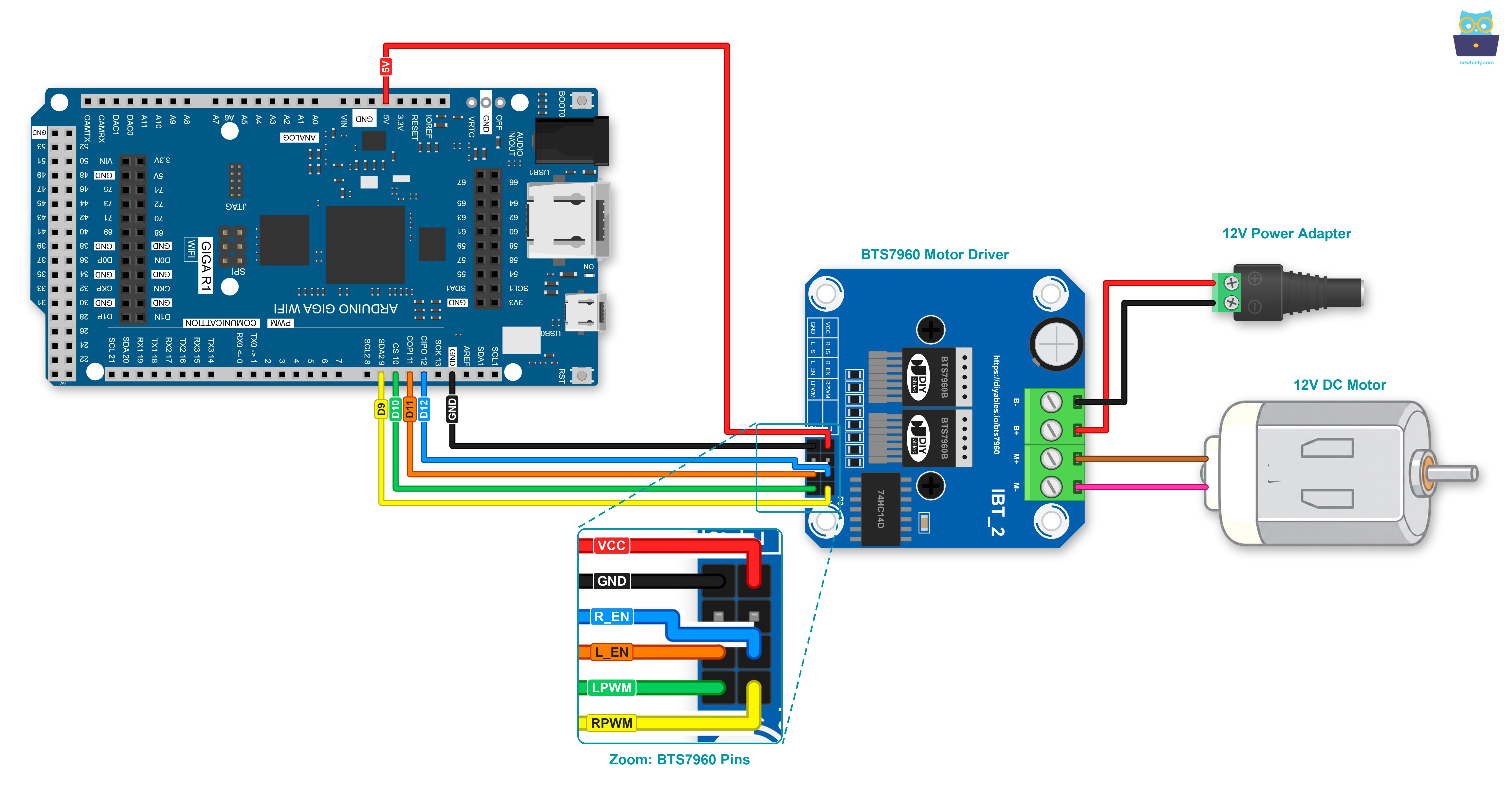
This image is created using Fritzing. Click to enlarge image
| BTS7960 Module | Connect To |
|---|---|
| RPWM | D9 of the Giga |
| LPWM | D10 of the Giga |
| R_EN | D12 of the Giga |
| L_EN | D11 of the Giga |
| VCC | 5V of the Giga |
| GND | GND of the Giga |
| R_IS, L_IS | nothing, leave them free |
| B+ | + of the 12V adapter, through the DC power jack |
| B- | - of the 12V adapter, through the DC power jack |
| M+, M- | the two wires of the 12V DC motor |
Look at the two enable wires: R_EN goes to D12, and L_EN goes to D11. The order is crossed, so check these two wires twice.
※ NOTE THAT:
- Check the + and - of the DC power jack before you plug in the adapter. A reversed adapter can ruin the module.
- Pick a 12V adapter that gives more current than your motor needs.
- Plug in the adapter last, after every wire is in place.
Using a real fan instead of the test motor? Pick one with a plain brushed DC motor. Many computer fans have a small control chip inside, and they are made to turn in one direction only. Do not run the reverse step of the script on such a fan.
How To Program BTS7960 With MicroPython
No library is needed. Everything comes from the machine module.
- Make RPWM and LPWM PWM outputs at 1 kHz, and set both of them to 0 first:
- Make the enable pins outputs, and switch the driver on. Do this only after both PWM pins are at 0:
- A speed in percent is easier to think about than a number up to 65535. One line converts it:
- Forward at 60%: set LPWM to 0 first, then put the PWM value on RPWM. For reverse, swap the roles of the two pins:
- Stop the motor. The first two lines alone are a brake, because the enables stay HIGH. Add the last two lines, and it becomes a coast:
1 kHz is far below the 25 kHz limit of the module. At low speed, the motor may hum or whine a little at this frequency. That is normal.
Arduino MicroPython Code - BTS7960 Motor Driver
The script puts the lines above into small helper functions: spin_forward(), spin_reverse(), brake() and coast(). Each one takes the speed as a percent from 0 to 100. One cycle takes about 10 seconds and has six steps, and each step prints one line:
- Speed up forward, from 0% to 100%.
- Stay at 100% for 2 seconds.
- Slow down to 0%.
- Brake for 1 second.
- Run in reverse at 50% for 2 seconds.
- Coast for 2 seconds with the driver off, then switch it on again.
Detailed Instructions
To run the script on the Arduino Giga with Thonny IDE:
- Have Thonny IDE ready on your computer.
- Your Arduino Giga must already run the MicroPython firmware.
- First time with MicroPython on this board? Read Getting Started with Arduino and MicroPython before you go on.
- Wire everything as in the diagram, but leave the 12V adapter unplugged for now.
- Connect the Giga to your computer with the USB Type-C cable.
- In Thonny IDE, click Tools Options.
- In the Interpreter tab, set MicroPython (generic).
- Choose the COM port of the Giga (e.g., COM33 on Windows or /dev/ttyACM0 on Linux).
- Paste the script into Thonny's editor.
- Save it on the board:
- Press Ctrl+S or click the Save button.
- Pick MicroPython device and type the name main.py.
- Click the green Run button (or press F5). Lines appear in the Shell, but the motor stays still, because B+ has no power yet.
- Only now push the 12V adapter plug into the DC power jack. Watch the motor, and read the Shell at the bottom of Thonny.
Step 4 and step 6 both end with a still motor, but not in the same way. In step 4 (brake), the driver joins the two motor wires, and the motor stops almost at once. In step 6 (coast), the driver lets go, and the motor rolls on for a moment. With a fan blade on the shaft, the difference is easy to see.
Does the motor turn the wrong way in the "forward" steps? Swap the M+ and M- wires in the screw terminal. Nothing in the code needs to change.
The last line of the Shell above came from the red Stop button in Thonny. When you stop the script, its last part switches the driver off. Without that part, the PWM pins could keep their last value, and the motor would keep running.
※ NOTE THAT:
The file is named main.py, so the Giga starts it by itself at every power-up. This means the motor can start as soon as the Giga and the 12V adapter both have power. Keep your hands and loose cables away from the shaft or the fan blade before you plug in.
BTS7960 or a Smaller Driver?
For a small toy motor, this module is more than you need. A short comparison:
- L298N: two motors, about 2A each. It loses about 2V inside, so the motor gets less than the supply voltage.
- DRV8833: two small motors on a low voltage. Tiny and handy, but not for big loads.
- BTS7960: only one motor, but a much higher current, and very little voltage is lost inside. Pick it for big fans, wiper motors, winches and heavy robots.
Does your fan only need ON and OFF, with no speed control? A relay is simpler. See Arduino MicroPython Controls Fan.
Two ideas to take the fan project further:
- Fan that follows the heat: read a probe as in Arduino MicroPython NTC Thermistor Temperature Sensor, and give the fan a bigger percent as the room gets warmer.
- Speed knob: read a potentiometer, turn its value into 0 to 100, and pass it to spin_forward().