
Arduino Giga R1 WiFi SW-420 Vibration Sensor
This guide walks through wiring and programming the SW-420 Vibration Sensor Module with the Arduino Giga R1 WiFi. The SW-420 is built around a spring-and-ball switch element: mechanical vibration or shock displaces the spring enough to momentarily make or break an internal contact, and an onboard LM393 comparator turns that mechanical event into a clean digital logic transition.
The comparator continuously weighs the switch signal against a reference voltage set by an onboard potentiometer, so no ADC channel or software threshold is ever needed on the microcontroller side — the module hands the Arduino Giga R1 WiFi a ready-to-use HIGH/LOW signal. Paired with the Giga R1 WiFi's STM32H747XI dual-core processor, this leaves plenty of headroom to react to vibration events instantly while other tasks (WiFi reporting, data logging, a second sensor) run in parallel.
Shock and vibration switches like the SW-420 show up in equipment condition monitoring (catching abnormal machine vibration before it causes failure), shipping and handling (flagging rough treatment of packages), tamper and intrusion alerts (detecting forced entry or drilling on an enclosure), and simple impact-triggered gadgets (knock sensors, vibrating-alarm toys). Because the output is already digital, none of these use cases require analog calibration in firmware.
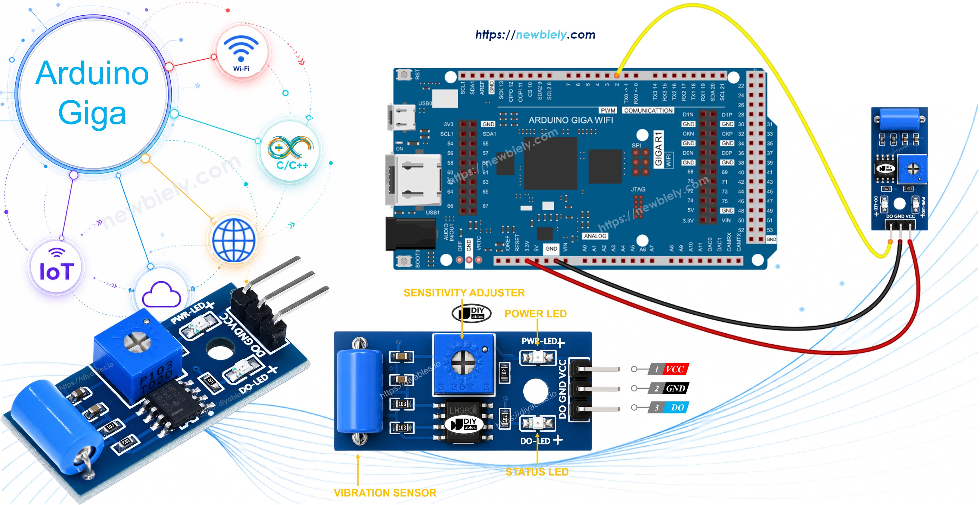
Hardware Preparation
Or you can buy the following kits:
| 1 | × | DIYables Sensor Kit (18 sensors/displays) |
Additionally, some of these links are for products from our own brand, DIYables .
Overview of SW-420 Vibration Sensor
Inside the SW-420's metal can sits a small spring-mounted mass that rests against a fixed contact under normal, motionless conditions. Vibration or mechanical shock briefly deflects the spring, interrupting or restoring that contact many times per second depending on the intensity of the disturbance.
Rather than exposing this raw, noisy mechanical signal directly, the module runs it through an onboard LM393 comparator. The comparator's trip point is set by a small onboard potentiometer, so the board's output pin only swings to a logic HIGH once the vibration amplitude clears the threshold you've dialed in — everything below that level is filtered out and the pin stays LOW. The result is a debounced, TTL-level digital signal, so detecting vibration is just a digitalRead() away, with no analog pin or conversion step involved.
Typical specifications: operating voltage 3.3V to 5V DC, purely digital output (there is no analog output pin on this module), adjustable sensitivity via the onboard potentiometer, and an LM393 comparator IC handling the signal conditioning.
The SW-420 Vibration Sensor Pinout
The module exposes three pins for the Arduino Giga R1 WiFi to connect to:
- VCC pin: Power input, accepts 3.3V to 5V DC from the Arduino's power rail.
- GND pin: Ground reference, 0V, shared with the Arduino Giga R1 WiFi's ground.
- DO pin: Digital output. Stays LOW while the module is undisturbed, and switches HIGH as soon as vibration or shock beyond the potentiometer's threshold is detected. Wire this pin to any Arduino Giga R1 WiFi digital input.
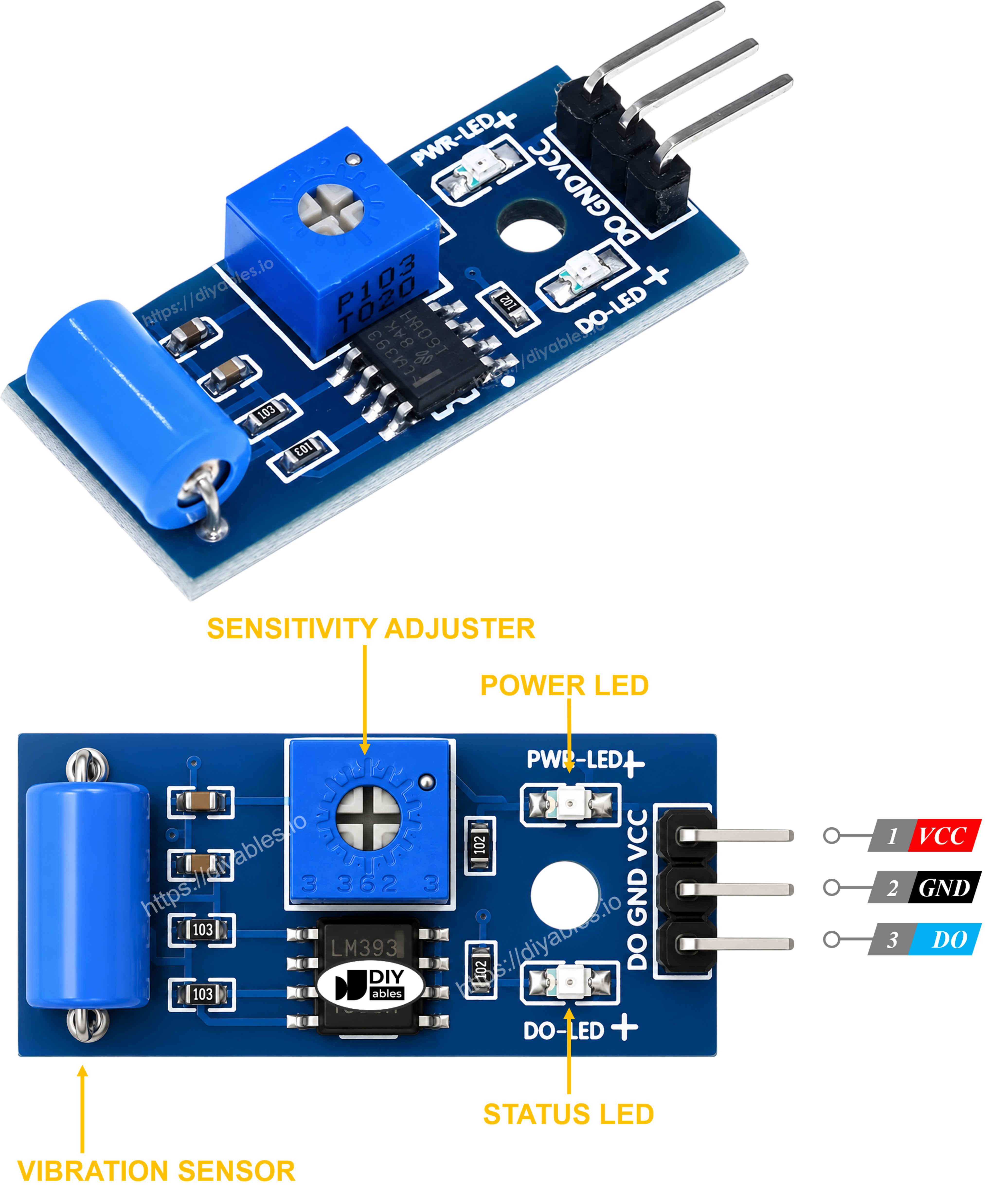
Two onboard LEDs help during bring-up: a steady power LED confirms VCC is present, and a second trigger LED tracks the DO pin in real time, lighting up on every detected shock so you can sanity-check the circuit without opening the Serial Monitor.
Wiring Note: Because the LM393 comparator actively drives the DO pin to both logic levels, no external pull-up or pull-down resistor is needed — the three wires (VCC, GND, DO) are all the connection this sensor requires.
How It Works
The SW-420 is entirely event-driven at the electrical level: the spring-and-ball element doesn't produce a graded signal, it just opens or closes a contact, and the comparator turns that into a decisive HIGH or LOW.
- At rest, the potentiometer-set reference voltage is not exceeded, so the comparator output — and therefore the DO pin — stays LOW.
- When vibration or an impact disturbs the spring enough to cross that threshold, the comparator output flips HIGH for as long as the disturbance persists (and briefly after, since the mechanical element takes a moment to settle).
Because the sensor reacts to sharp shocks as readily as to sustained vibration, a single knock can produce a short HIGH pulse rather than a clean level change. If your project needs to count discrete events, treat each LOW-to-HIGH edge as one "hit" instead of relying purely on the raw current state.
Wiring Diagram
Only three wires connect the SW-420 module to the Arduino Giga R1 WiFi — power, ground, and the digital output line:
| SW-420 Vibration Sensor Pin | Arduino Giga R1 WiFi Pin |
|---|---|
| VCC | 5V |
| GND | GND |
| DO | Digital Pin 2 |
Digital pin 2 doubles as external interrupt 0 on the Giga R1 WiFi, which is handy if a later revision of the sketch needs to catch fast vibration pulses via attachInterrupt() instead of polling in loop(). For the basic polling example in this guide, any digital pin would work equally well.
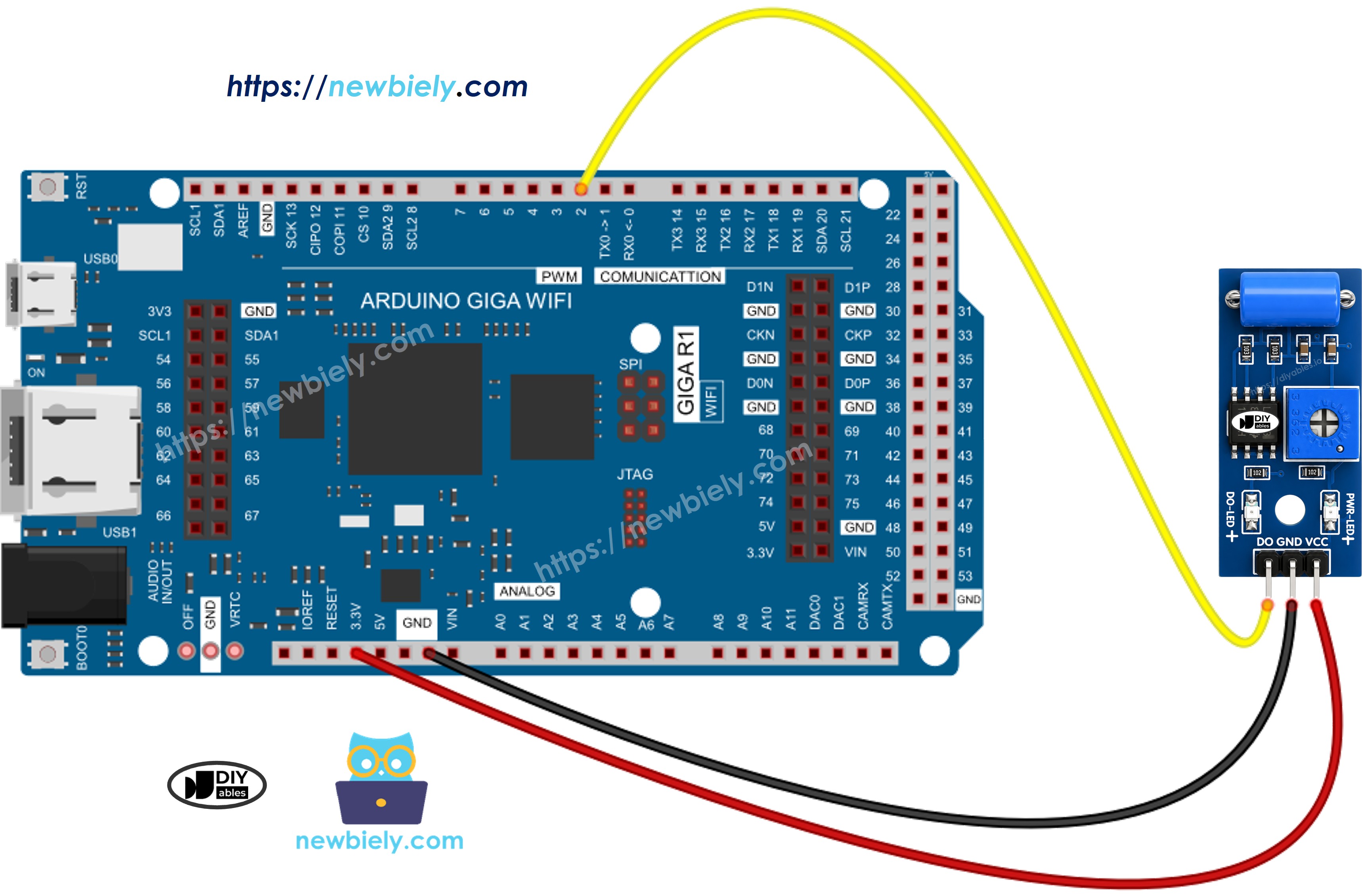
This image is created using Fritzing. Click to enlarge image
How To Program For SW-420 Vibration Sensor
The firmware side of this project only needs two GPIO calls — there is no library to install and nothing to calibrate in software, since the sensitivity is already set on the module's potentiometer.
Initialize the selected Arduino pin as a digital input to enable reading of the sensor's output state. The pinMode() function configures the GPIO direction:
Sample the comparator's current output with digitalRead(), which reports the logic level present on the pin at the moment it's called:
Because the DO pin idles LOW and only rises to HIGH while vibration is being detected, comparing the new reading against the previously stored one lets the sketch report the exact moment a disturbance starts and the moment it settles back down, rather than just printing the current level on every loop.
Arduino Giga R1 WiFi Code - Detecting the vibration
Detailed Instructions
Follow these instructions step by step:
- Upload the sketch: Open the code above in Arduino IDE, select the Arduino Giga R1 WiFi board and its COM port, then click Upload and wait for the IDE to confirm success.
- Wire the module: Connect the SW-420 to the Arduino Giga R1 WiFi following the wiring diagram. The module's power LED should light up as soon as VCC is applied.
- Open the Serial Monitor: Go to Tools → Serial Monitor and set the baud rate to 9600.
- Trigger some vibration: Tap or lightly shake the sensor module. Each tap should print a detection message, and the trigger LED on the module should flash in step with it.
- Adjust sensitivity if needed: Turn the onboard potentiometer clockwise or counter-clockwise with a small screwdriver to make the module more or less reactive to weak vibration.
Tip: With WiFi still available on this board, the same detection logic can be extended to push an alert (email, MQTT message, webhook call) the moment vibration is detected, without adding any extra sensor hardware.
Serial Monitor Output
From here, the detection event can drive anything you like — lighting an LED, sounding a buzzer, logging a timestamp to storage, or publishing a notification over WiFi. The rest of this site's tutorials walk through wiring those outputs up in detail.
Application Ideas
Machine Condition Monitoring: Mount the SW-420 on motors, pumps, or fans to catch abnormal vibration patterns that often precede mechanical failure. The Arduino Giga R1 WiFi's networking capability lets a detected anomaly be reported immediately rather than discovered on the next manual inspection.
Shock-Aware Shipping Boxes: Embed the sensor in a package to flag rough handling in transit. Since the module needs no analog calibration, a simple event counter is enough to record how many significant impacts a shipment experienced.
Tamper and Intrusion Alerts: Attach the sensor to a door, window frame, or equipment cabinet to detect forced entry, drilling, or prying. Combined with the Giga R1 WiFi's WiFi radio, a triggered event can be turned into an instant push notification.
Troubleshooting
If the SW-420 vibration sensor isn't behaving as expected, work through these checks:
- Adjust the sensitivity potentiometer: If detections happen too easily (or not easily enough), turn the onboard trimmer to raise or lower the trigger threshold, then retest with a light tap.
- Isolate the sensor from ambient vibration: Loose mounting or a vibrating nearby surface (fans, desks, motors) can cause continuous false triggers. Mount the module firmly to the object you actually want to monitor.
- Recheck the wiring: Confirm VCC, GND, and DO are connected to the correct pins and that none of the jumper wires are loose.
- Verify the power supply: An unstable or noisy supply voltage can make the comparator's output chatter; power the board from a solid 5V or 3.3V source.