ESP32 C3 Super Mini - Electromagnetic Lock
Learning to control an electromagnetic lock with ESP32 C3 Super Mini is a great introduction to smart door systems and home security projects. This tutorial shows you how to wire and program a maglock using a relay module.
In this tutorial, you'll learn:
- What an electromagnetic lock is and how it works
- How to wire an EM lock to ESP32 C3 Super Mini using a relay
- How to write code to control the magnetic lock
- How to test lock and unlock functionality
- How to integrate buttons for access control
Hardware Preparation
Or you can buy the following kits:
| 1 | × | DIYables Sensor Kit (18 sensors/displays) |
Additionally, some of these links are for products from our own brand, DIYables .
Overview of Electromagnetic Lock
An electromagnetic lock (or maglock) is a locking device that uses electromagnets to hold doors securely closed.
Key Features:
- Uses magnetic force for locking (no mechanical parts)
- Requires constant power to stay locked
- Very strong holding force (typically 280kg to 500kg)
- Fail-safe design (unlocks when power fails)
- Commonly used in commercial access control systems
Why It's Great for Beginners:
- Simple two-wire connection
- Easy to control with a relay
- No complex mechanisms or moving parts
- Works well with ESP32 projects and door automation
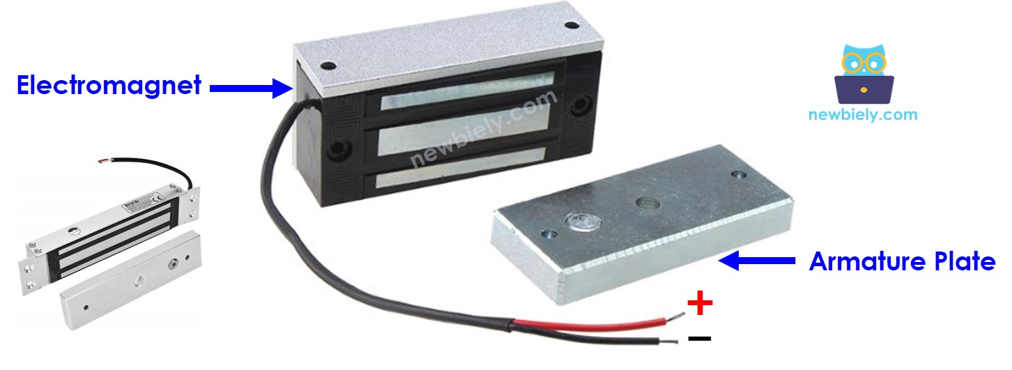
Electromagnetic Lock Components
The electromagnetic Lock is composed of two components:
- Armature plate: Attached on the moving part of the door (the door itself)
- Electromagnet: Attached on the door frame with two wires connected to power source
When the door is closed, two components are in contact with each other.
How Electromagnetic Lock Works
- Powered (Locked): When the electromagnet receives power ⇒ it creates a strong magnetic field ⇒ attracts the armature plate ⇒ door is locked
- Unpowered (Unlocked): When power is cut ⇒ no magnetic field ⇒ armature plate releases ⇒ door is unlocked
Important Notes:
- Electromagnetic locks require high voltage (12V, 24V, or 48V power supply)
- ESP32 C3 Super Mini pins output only 3.3V and low current
- A relay module is required to control the high-voltage power safely
See ESP32 C3 Super Mini - Relay tutorial for relay basics.
Control Logic with Relay (Normally Open Mode):
- ESP32 pin LOW ⇒ relay open ⇒ electromagnet unpowered ⇒ door unlocked
- ESP32 pin HIGH ⇒ relay closed ⇒ electromagnet powered ⇒ door locked
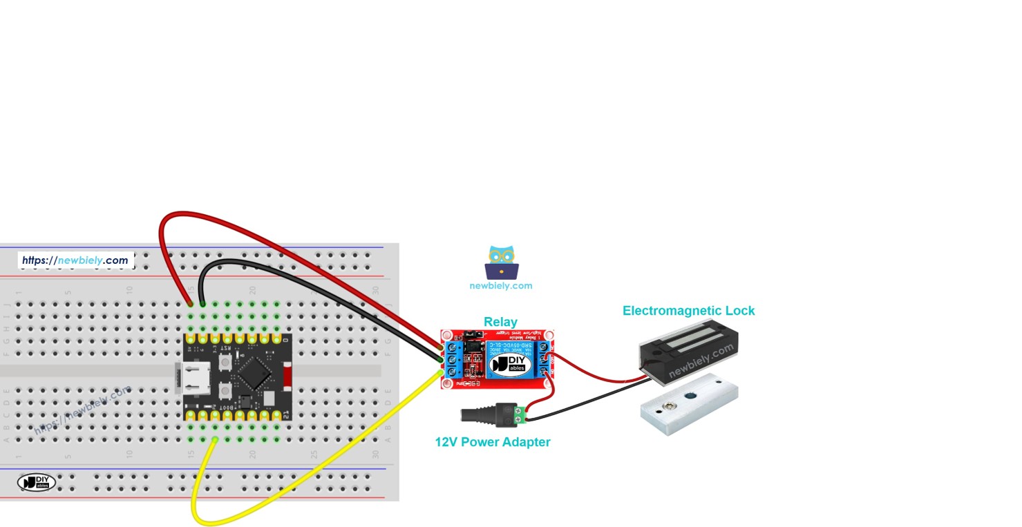
Wiring Diagram between Electromagnetic Lock and ESP32
Here's how to connect the electromagnetic lock to your ESP32 C3 Super Mini using a relay module.
Safety Notes:
- Always disconnect power before wiring
- Double-check voltage ratings on your electromagnetic lock
- Ensure the relay is rated for your lock's power requirements
- Never connect the EM lock directly to ESP32 pins
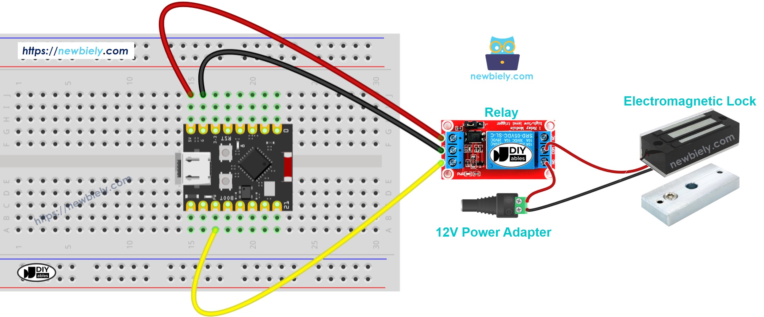
This image is created using Fritzing. Click to enlarge image
Wiring Connections:
| Component Pin | ESP32 C3 Super Mini Pin | Notes |
|---|---|---|
| Relay Signal (IN) | D7 | Controls relay on/off |
| Relay VCC | 5V | Powers the relay module |
| Relay GND | GND | Common ground |
| Relay COM | 12V Power + | From power adapter |
| Relay NO | EM Lock Wire 1 | Normally open connection |
| EM Lock Wire 2 | 12V Power - | Completes the circuit |
ESP32 C3 Super Mini Code
This code example demonstrates basic electromagnetic lock control by locking and unlocking the door every 5 seconds.
What This Code Does:
- Initializes D7 as an output pin for relay control
- Locks the door (HIGH signal) for 5 seconds
- Unlocks the door (LOW signal) for 5 seconds
- Repeats the cycle continuously
- Prints lock status to Serial Monitor
Detailed Instructions
- New to ESP32 C3 Mini? Complete our Getting Started with ESP32 C3 Mini tutorial first to set up your development environment.
- Setup Arduino IDE: If this is the first time you use ESP32 C3 Super Mini, see how to setup environment for ESP32 C3 Super Mini on Arduino IDE.
- Upload the Code: Copy the above code and paste it to Arduino IDE.
- Compile and Upload: Click the Upload button on Arduino IDE to compile and upload code to your ESP32 C3 Super Mini board.
- Test the Lock: Place the armature plate close to the electromagnet.
- Observe the Action: Watch the attraction between armature plate and electromagnet change every 5 seconds.
- Open Serial Monitor: Set baud rate to 115200 to see lock status messages.
- Pro Tip: Mark the armature plate position on your door frame for easy alignment during installation.
Serial Monitor Output
Open the Serial Monitor and you'll see output like this:
Real-World Applications
Electromagnetic locks controlled by ESP32 C3 Super Mini can be used in many practical projects:
- Smart Home Entry: Build keypad or RFID-based door access systems
- Office Access Control: Create employee badge readers with logging
- Lab or Tutorial Security: Restrict access to sensitive areas with authentication
- Automated Gates: Control gate locks with remote triggers or sensors
- Cabinet Security: Lock storage units or display cases electronically
- IoT Security Systems: Integrate with WiFi for remote lock/unlock via smartphone app
Video Tutorial
Watch the video below for a visual walkthrough of this project.
...VIDEO https://www.youtube.com/embed/5yvlkAOr9C4
...VIDEO
Challenge Yourself
Take your electromagnetic lock project to the next level with these challenges:
- Easy: Add an LED indicator that lights up when the door is locked
- Easy: Modify the timing to keep the door unlocked for 10 seconds instead of 5
- Medium: Add a pushbutton to manually unlock the door on demand
- Medium: Implement a simple PIN code system using multiple buttons
- Advanced: Create a web server to control the lock remotely via WiFi
- Advanced: Add RFID authentication for keyless entry with multiple user cards