
ESP32 C3 Super Mini - Control Heating Element
Learn how to control a heating element with your ESP32 C3 Super Mini microcontroller using a relay module. This beginner-friendly tutorial shows you everything you need to build heating control projects.
In this tutorial, you'll learn:
- What a heating element is and how it works with ESP32
- How to wire a heating element safely using a relay
- How to write ESP32 code to control heating on/off cycles
- How to build the foundation for heating system projects
- How to drive the heater with a MOSFET module and pick its heat level
You can switch the heater through a relay, or through a MOSFET module. The relay knows only ON and OFF. The MOSFET module also switches ON and OFF, but it can set how much power the heater gets, so you choose a low, medium or high heat level. It is silent, and switching often does not wear it out. We cover both ways here.
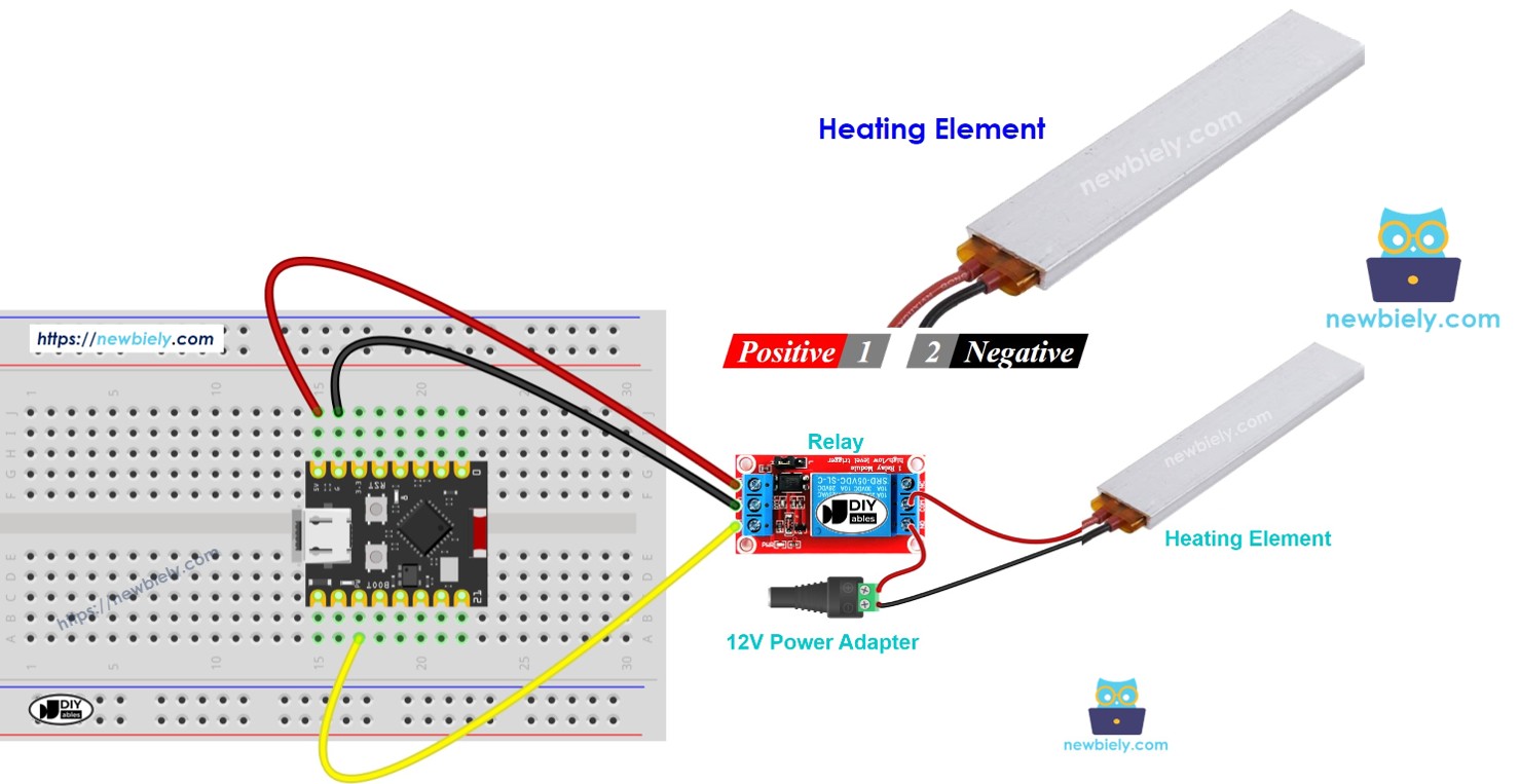
Hardware Preparation
Or you can buy the following kits:
| 1 | × | DIYables Sensor Kit (18 sensors/displays) |
Additionally, some of these links are for products from our own brand, DIYables .
Overview of Heating Element
A heating element is an electrical component that converts electrical energy into heat when powered.
Key features:
- Operates on 12V DC power supply
- Generates heat when current flows through it
- Requires relay control for ESP32 C3 Super Mini compatibility
- Commonly used in warming and temperature control projects
- Perfect for learning basic heating system automation
Why use with ESP32:
- Build automated heating projects
- Create temperature-controlled systems
- Learn real-world IoT applications
- Practice safe relay-based device control
Pinout
The heating element has a simple two-pin configuration for power connection.
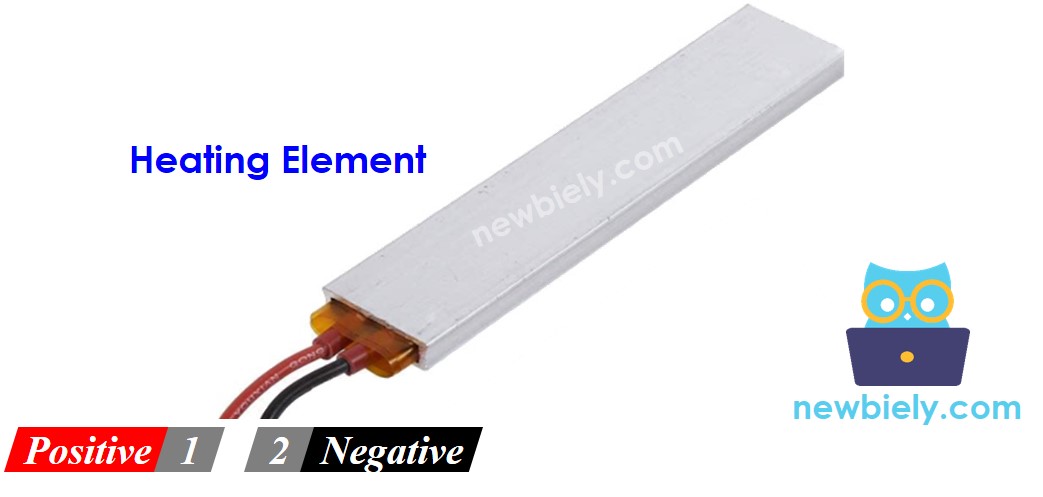
- Positive (+) pin (red): Connects to 12V positive terminal of DC power supply
- Negative (-) pin (black): Connects to GND negative terminal of DC power supply
How to Control Heating Element
The ESP32 C3 Super Mini controls the heating element indirectly through a relay module.
Control mechanism:
- ESP32 C3 Super Mini cannot directly power 12V heating elements
- A relay acts as an electronic switch between power supply and heating element
- ESP32 sends digital signals to the relay (HIGH/LOW)
- Relay switches the 12V power circuit on/off
- This allows safe control of high-power devices with low-power microcontrollers
Important: If you're new to relays, check out our ESP32 C3 Super Mini - Relay tutorial first to understand pinout, wiring, and programming basics.
For the second way, the ESP32 C3 Super Mini - MOSFET Module tutorial explains the module's terminals and how PWM sets the power.
Relay vs MOSFET Module for a Heating Element
| Relay | MOSFET Module | |
|---|---|---|
| Heater control | Full heat or no heat | Full heat, no heat, or any level between (PWM) |
| Sound | Clicks on every switch | Silent |
| Switching time | Milliseconds, mechanical | Almost instant |
| Long-term use | Contacts wear, worse with frequent switching | Nothing moves, nothing wears |
| Power type | AC or DC heaters | DC heaters only |
| Heater supply | Any voltage within the relay rating | 6V or more |
| Isolation | Coil is separate from the contacts | PC817 optocoupler inside |
| Pick it when | The heater runs on AC, or you need only ON/OFF | A 12V DC heater that switches often or needs a set heat level |
A thermostat turns the heater ON and OFF many times a day, so the MOSFET module is a good match for a 12V DC heating element. If your heater runs on AC mains, you must stay with the relay.
Wiring Diagram
Follow this wiring diagram to safely connect your ESP32 C3 Super Mini to the heating element via relay.
WARNING
Please be careful. It can burn you and your house. This is a serious topic, and we want you to be safe. If you're NOT 100% sure what you are doing, do yourself a favor and don't touch anything. Ask someone who knows! We do NOT take any responsibility for your safety.
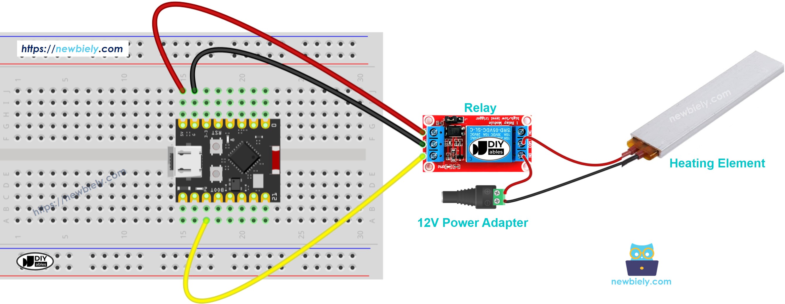
This image is created using Fritzing. Click to enlarge image
Safety notes:
- Double-check all connections before applying power
- Never touch the heating element when powered on
- Ensure proper ventilation during operation
- Use appropriate wire gauge for 12V connections
- Keep flammable materials away from the heating element
ESP32 C3 Super Mini Code
The following code demonstrates basic heating element control by turning it ON for five seconds, then OFF for five seconds in a repeating cycle.
What this code does:
- Configures a digital pin to control the relay
- Turns the heating element ON (5 seconds)
- Turns the heating element OFF (5 seconds)
- Repeats the cycle continuously
- Provides a foundation for temperature control projects
Code Explanation
The above ESP32 C3 Super Mini code contains line-by-line explanation. Please read the comments in the code!
Detailed Instructions
- New to ESP32 C3 Mini? Complete our Getting Started with ESP32 C3 Mini tutorial first to set up your development environment.
- Connect hardware: Wire the ESP32 C3 Super Mini, relay, and heating element according to the wiring diagram above.
- Plug in USB: Connect your ESP32 C3 Super Mini to your computer using the USB Type-C cable.
- Open Arduino IDE: Launch the Arduino IDE software on your computer.
- Select board: Choose the correct ESP32 C3 Super Mini board from the Tools menu.
- Select port: Choose the COM port that your ESP32 is connected to.
- Copy code: Copy the complete code from the code section above.
- Paste code: Paste it into a new Arduino IDE sketch window.
- Upload code: Click the Upload button and wait for the process to complete.
- Test operation: Observe the heating element turning on and off every 5 seconds.
- Check temperature: Carefully feel for heat (without touching) to verify operation.
- Pro Tip: Start with short ON times while testing to verify your wiring is correct before running longer heating cycles.
ESP32 C3 Super Mini Code - Heating Element with MOSFET Module
This part uses the MOSFET module in place of the relay. With PWM on GPIO4, the heater gets only part of the 12V power, so you can choose how warm it gets.
MOSFET Module Wiring Diagram
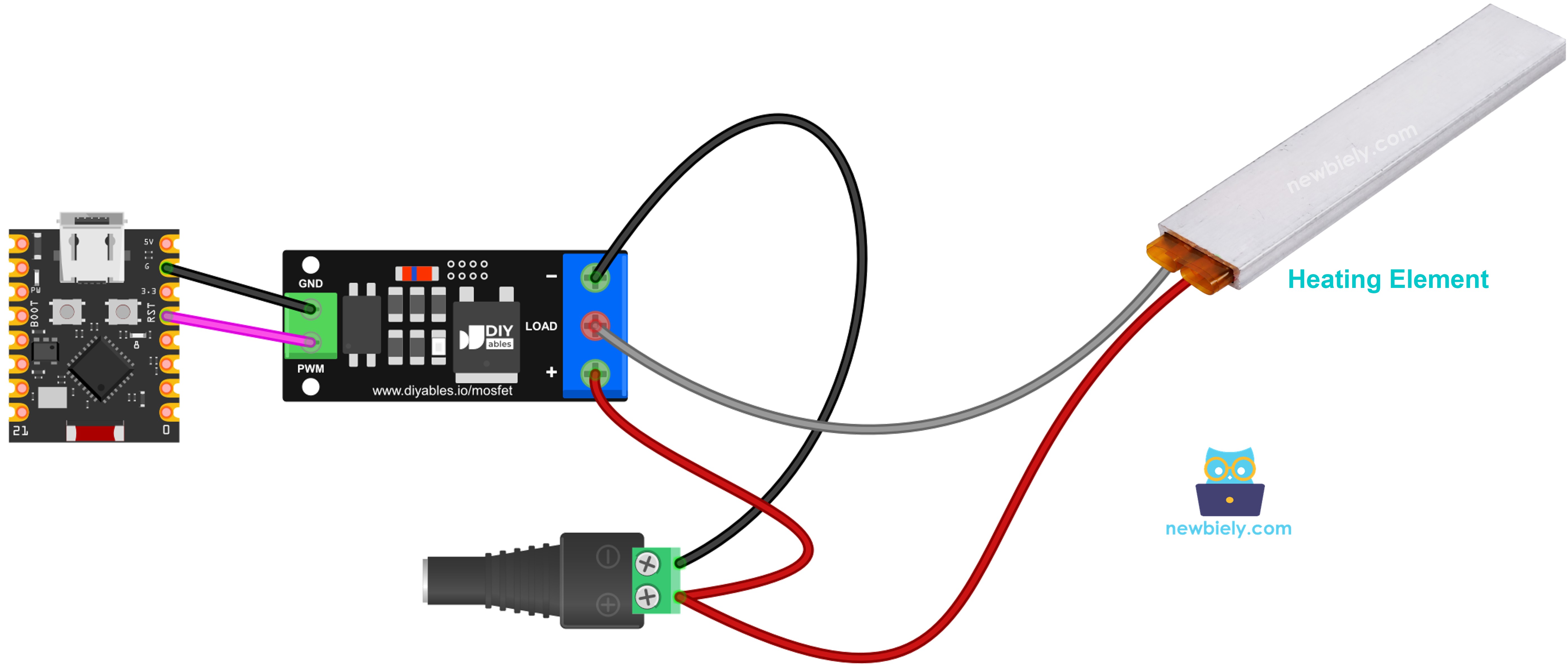
This image is created using Fritzing. Click to enlarge image
- GPIO4 on the ESP32 C3 Super Mini → PWM on the module
- GND on the ESP32 C3 Super Mini → GND on the module
- 12V adapter + and heater + → both into the module's + terminal
- Heater − → module LOAD
- 12V adapter − → module −
- No flyback diode is needed. A heating element is not a coil.
The same safety warning as above applies here. The heater gets hot even at low power.
Code
How the heater reacts to this code:
- 2 seconds at full power, then 2 seconds off
- Then the power climbs from 10% to 100% and falls back to 0%, step by step
- A heater warms up and cools down slowly. You will not feel each step at once; the change shows after a while. For a real test, set one fixed level and wait a few minutes
Detailed Instructions
- Prepare Arduino IDE and select the board as in the relay Quick Steps above
- Wire the heating element to the MOSFET module (see the list and diagram)
- Paste the code into Arduino IDE and click Upload
- Plug in the 12V adapter
- Open the Serial Monitor at 9600 baud to see the power level
Tip: give the module a heater supply of at least about 6V, and DC only. An AC heater needs the relay.
Application Ideas
Use this ESP32 heating element control setup as the foundation for various heating automation projects.
- Build a simple thermostat-controlled heating system
- Create a pet enclosure temperature regulator
- Design a plant propagation warming mat controller
- Make a DIY sous vide cooking temperature controller
- Develop a small-scale incubator for hatching projects
- Build a drying cabinet with automated heating cycles
Video Tutorial
Watch the video below for a visual walkthrough of this project.
...VIDEO /videos/tutorial/KITS_ESP_HEATING_ELEMENT.mp4
...VIDEO
Challenge Yourself
Take your ESP32 heating element skills to the next level with these progressive challenges.
- Easy: Modify the code to change the ON/OFF time intervals to 10 seconds each.
- Easy: Add a status LED that lights up when the heating element is active.
- Medium: Integrate a temperature sensor (DS18B20) to display current temperature on Serial Monitor.
- Medium: Create a simple thermostat that turns heating on when temperature drops below a set point.
- Advanced: Build a PID temperature controller for precise heating control with minimal overshoot.