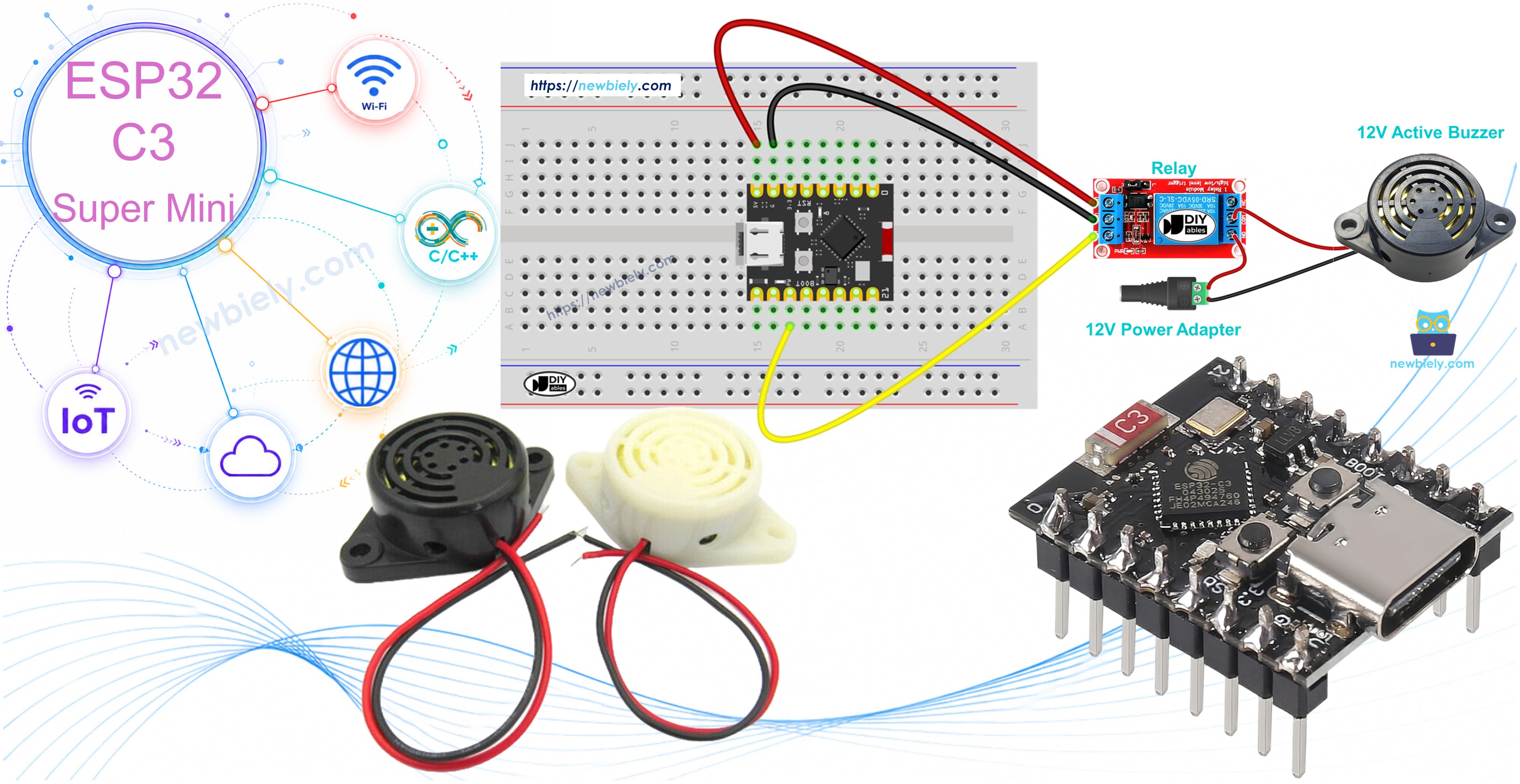
ESP32 C3 Super Mini - Buzzer
Learn how to program your ESP32 C3 Super Mini to control a 12V active buzzer and generate loud, attention-grabbing sounds perfect for alarms and notifications. This beginner-friendly tutorial walks you through everything you need to create a working buzzer project.
In this tutorial, you'll learn:
- What a 12V active buzzer is and why it needs a relay
- How to wire the buzzer to ESP32 C3 Super Mini using a relay module
- How to write code to control the buzzer ON/OFF timing
- How to create loud alarm sounds for your projects
Note: If you want to control 5V active/passive buzzer, check out this ESP32 C3 Super Mini Piezo Buzzer tutorial
Hardware Preparation
Or you can buy the following kits:
| 1 | × | DIYables Sensor Kit (18 sensors/displays) |
Additionally, some of these links are for products from our own brand, DIYables .
Overview of 12V Active Buzzer
The 12V Active Buzzer is an electronic buzzer that produces a loud, high-decibel sound suitable for alarm systems and attention alerts.
Key features:
- Operates at 12V DC power supply
- Produces loud sound (much louder than standard 5V buzzers)
- "Active" means it has built-in oscillator - just apply power to make sound
- Perfect for security alarms, notification systems, and warning signals
- Requires external power supply (cannot be powered directly by ESP32)
- Must be controlled through a relay module for safe operation
Why use a 12V buzzer?
- Significantly louder than 5V buzzers
- Better for outdoor or noisy environments
- Ideal for alarm and alert systems where sound needs to carry
Pinout
The 12V Active Buzzer pinout is simple with only two connection points.
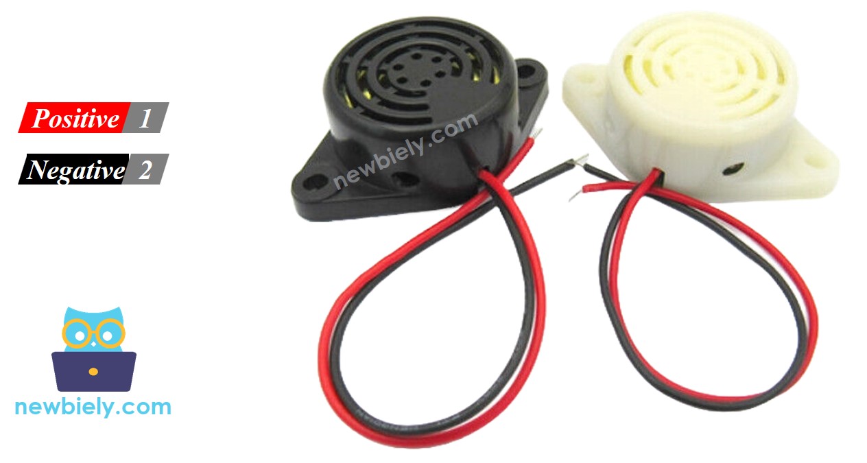
- Negative (-) pin (black): Connect to GND of 12V DC power supply
- Positive (+) pin (red): Connect to 12V positive of DC power supply
How to Control 12V Active Buzzer
The ESP32 C3 Super Mini outputs only 3.3V, which is not enough to power a 12V buzzer directly.
Control method:
- Use a relay module as a switch between ESP32 and the buzzer
- ESP32 C3 Super Mini controls the relay with a digital pin
- Relay switches the 12V power supply to the buzzer ON or OFF
- This keeps your ESP32 safe while controlling high-voltage devices
Important: If you're new to relays, check out the ESP32 C3 Super Mini - Relay tutorial to understand pinout, operation, and programming basics.
Wiring Diagram
Follow this wiring diagram to connect your ESP32 C3 Super Mini to the 12V active buzzer through a relay module.
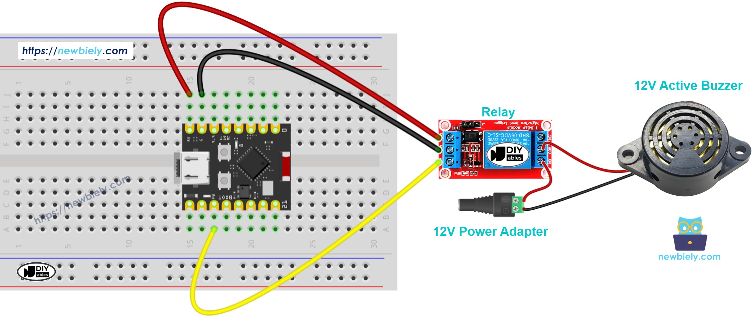
This image is created using Fritzing. Click to enlarge image
Safety notes:
- Note: Double-check 12V power supply polarity before connecting - reversed polarity can damage the buzzer
- Note: Keep 12V wiring separate from ESP32 signal wires to avoid electrical interference
| Component Pin | Connection Point |
|---|---|
| ESP32 Pin 2 | Relay Signal Pin (IN) |
| ESP32 GND | Relay GND |
| ESP32 5V | Relay VCC |
| Relay COM | 12V Power Supply (+) |
| Relay NO | Buzzer (+) Red Wire |
| Buzzer (-) Black Wire | 12V Power Supply GND (-) |
ESP32 C3 Super Mini Code
Here's the code to control your 12V active buzzer - it turns the buzzer ON for 1 second, then OFF for 2 seconds in a repeating pattern.
What this code does:
- Sets up GPIO pin 2 to control the relay
- Turns the buzzer ON for 1 second (relay activated)
- Turns the buzzer OFF for 2 seconds (relay deactivated)
- Repeats the pattern continuously for alarm-like beeping
- Uses simple digitalWrite commands for easy customization
Detailed Instructions
- New to Arduino? Start with our ESP32 C3 Super Mini Getting Started guide first.
- Setup environment: If this is your first time using ESP32 C3 Super Mini, follow the Arduino IDE setup guide
- Connect hardware: Wire the ESP32 C3 Super Mini, relay, buzzer, and 12V power supply according to the wiring diagram above
- Connect to PC: Plug your ESP32 C3 Super Mini into your computer using the USB Type-C cable
- Open Arduino IDE: Launch the Arduino IDE and select the correct board and port
- Upload code: Copy the code above, paste it into Arduino IDE, and click the Upload button
- Test buzzer: Listen for the buzzer to beep ON for 1 second, OFF for 2 seconds repeatedly
- Verify operation: The relay LED should also blink in sync with the buzzer sound
- Pro Tip: Adjust the delay() values in the code to create different beep patterns - shorter delays make rapid alarm sounds, longer delays create slow warning beeps
Code Explanation
The code comments explain each line in detail - read through them to understand how the buzzer control works!
Key functions used:
- pinMode() - Configures GPIO pin 2 as an output to control the relay
- digitalWrite(HIGH) - Activates relay, connecting 12V to buzzer (sound ON)
- digitalWrite(LOW) - Deactivates relay, disconnecting power (sound OFF)
- delay() - Pauses program execution to control timing
Applications and Project Ideas
Use your ESP32 C3 Super Mini 12V active buzzer setup in these practical projects:
- Security alarm system: Trigger loud alerts when motion sensors detect intrusion
- Timer notifications: Create kitchen timers or workout interval buzzers
- Door/window alerts: Sound alarm when doors or windows open unexpectedly
- Water leak detector: Connect with moisture sensor to alert for leaks
- Temperature warnings: Pair with temperature sensor for overheat alarms
- Reminder system: Build medication or appointment reminder device
- IoT alarm system: Combine with WiFi to create remote-controlled security alerts
Video Tutorial
Watch the video below for a visual walkthrough of this project.
Challenge Yourself
Take your buzzer project to the next level with these challenges:
- Easy: Modify the code to create an SOS pattern (3 short beeps, 3 long beeps, 3 short beeps)
- Easy: Add a button to manually trigger the buzzer ON/OFF
- Medium: Create a melody by programming different beep durations and pauses
- Medium: Use a motion sensor to trigger the alarm only when movement is detected
- Advanced: Build a smartphone-controlled alarm using ESP32 WiFi and Blynk app
- Advanced: Create a multi-zone alarm system with multiple buzzers controlled independently