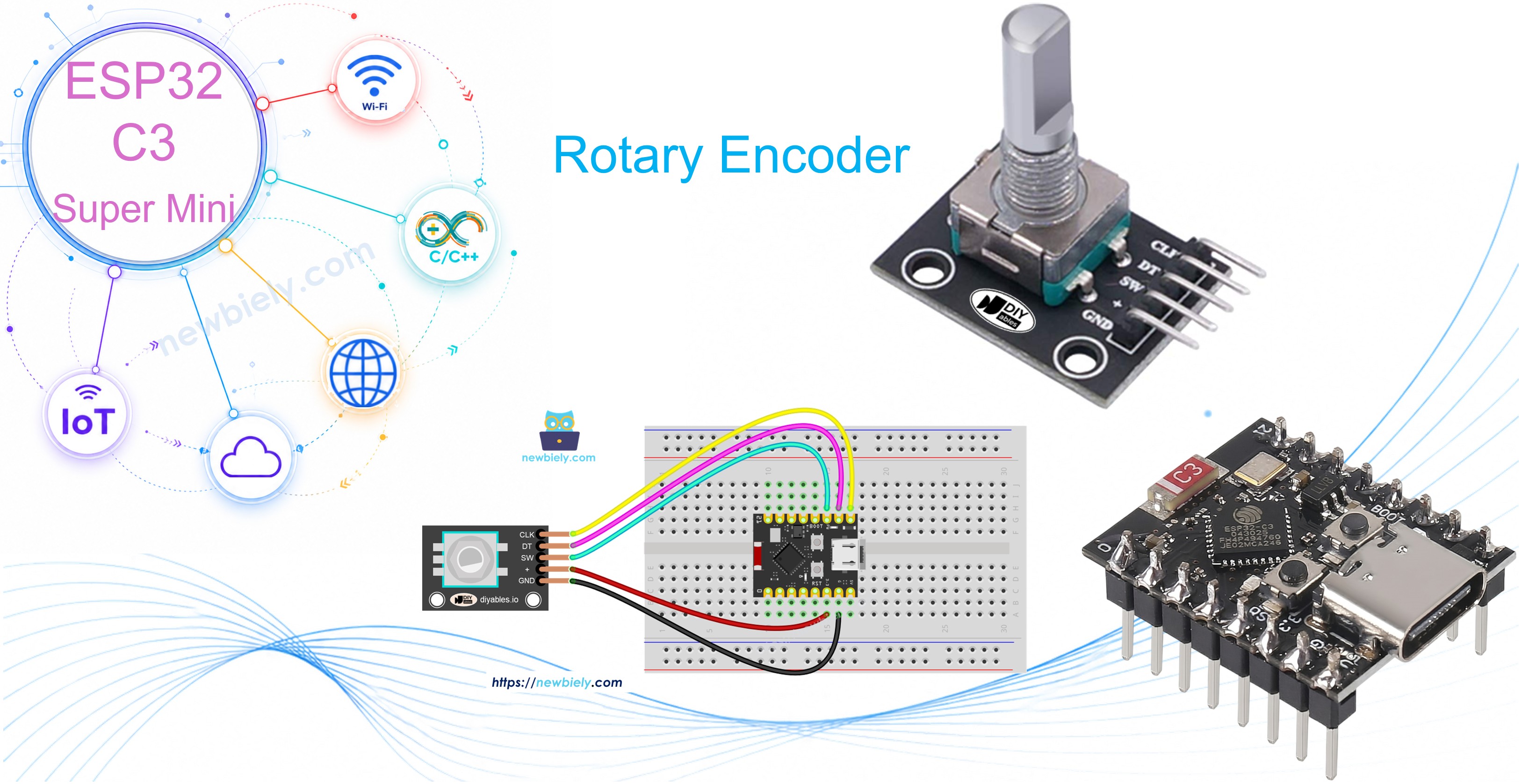
ESP32 C3 Super Mini - Rotary Encoder
Learn how to use a rotary encoder with your ESP32 C3 Super Mini to detect rotation direction and position. This beginner-friendly tutorial covers everything from wiring to coding with interrupt-based techniques.
In this guide, you'll learn:
- What rotary encoders are and how they differ from potentiometers
- How incremental encoders work and detect rotation
- How to wire a rotary encoder to ESP32 C3 Super Mini
- How to program ESP32 C3 Super Mini to read encoder direction and position
- How to use interrupts for more efficient encoder reading
- Real-world applications for rotary encoder projects
Hardware Preparation
| 1 | × | ESP32 C3 Super Mini | |
| 1 | × | USB Cable Type-A to Type-C (for USB-A PC) | |
| 1 | × | USB Cable Type-C to Type-C (for USB-C PC) | |
| 1 | × | Rotary Encoder | |
| 1 | × | Breadboard | |
| 1 | × | Jumper Wires |
Or you can buy the following kits:
| 1 | × | DIYables Sensor Kit (18 sensors/displays) |
Additionally, some of these links are for products from our own brand, DIYables .
Overview of Rotary Encoder
A rotary encoder is a position sensor that converts rotational movement into electrical signals to determine direction and rotation amount.
Key types of rotary encoders:
- Incremental encoder: Uses pulse signals to measure relative position changes - perfect for tracking rotation
- Absolute encoder: Provides unique position codes that retain position data even when power is lost
Why rotary encoders are great for beginners:
- Easy to use with just a few pins
- Provide both rotation direction and button press detection
- Can rotate continuously without mechanical limits
- Work great with interrupts for efficient ESP32 C3 Super Mini projects
This tutorial focuses on incremental rotary encoders, the most common type for Arduino and ESP32 projects.
Rotary Encoder Module Pinout
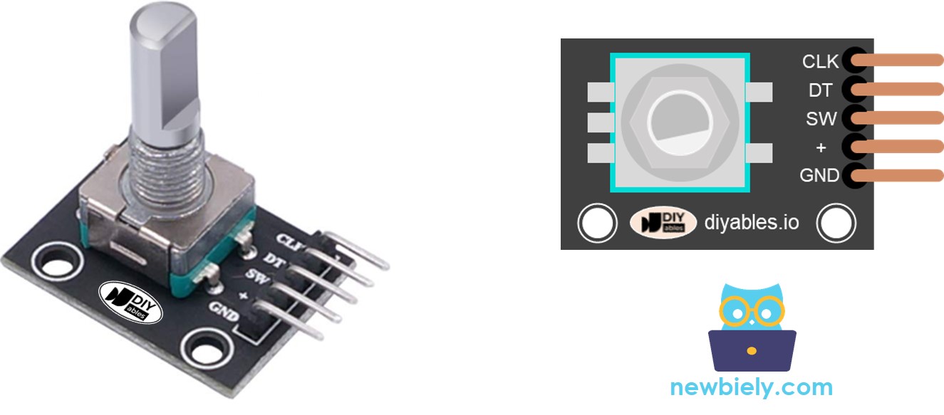
The rotary encoder module has 5 pins you'll connect to your ESP32 C3 Super Mini:
- CLK pin (Output A): Primary pulse output that signals rotation - outputs one complete cycle (LOW → HIGH → LOW) per detent click
- DT pin (Output B): Secondary pulse output that lags CLK by 90 degrees to determine rotation direction (clockwise or counterclockwise)
- SW pin: Push button connection - normally open, reads HIGH when not pressed and LOW when pressed (requires pull-up resistor)
- VCC pin (+): Power supply connection - connect to 3.3V or 5V
- GND pin: Ground connection - connect to GND (0V)
Rotary Encoder vs Potentiometer
You might confuse the rotary encoder with a potentiometer, but they serve different purposes.
Key differences:
- Rotation range: Rotary encoders rotate continuously 360° while potentiometers have limited rotation (typically 270°)
- Output type: Encoders output digital pulses while potentiometers output analog voltage
- Position tracking: Encoders track relative movement (how much it turned) while potentiometers track absolute position
- Best use: Encoders excel at tracking rotation amount and direction; potentiometers are better when you need exact position values
- Modern design: Rotary encoders are the digital evolution of potentiometers with enhanced capabilities
How Rotary Encoder Works
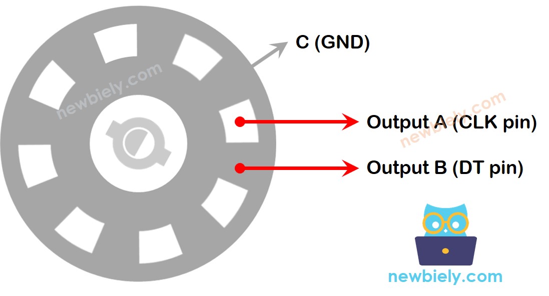
Internal mechanism:
- A slotted disc inside connects to pin C (common ground)
- Pins A and B make contact with the common ground as the knob rotates
- The order of contact between A and B determines rotation direction
- This creates two pulse signals that are 90 degrees out of phase (quadrature encoding)
Detecting rotation direction:
- Clockwise rotation: Pin A contacts ground before pin B
- Counterclockwise rotation: Pin B contacts ground before pin A
- By monitoring pin B's state when pin A changes, the ESP32 C3 Super Mini determines rotation direction
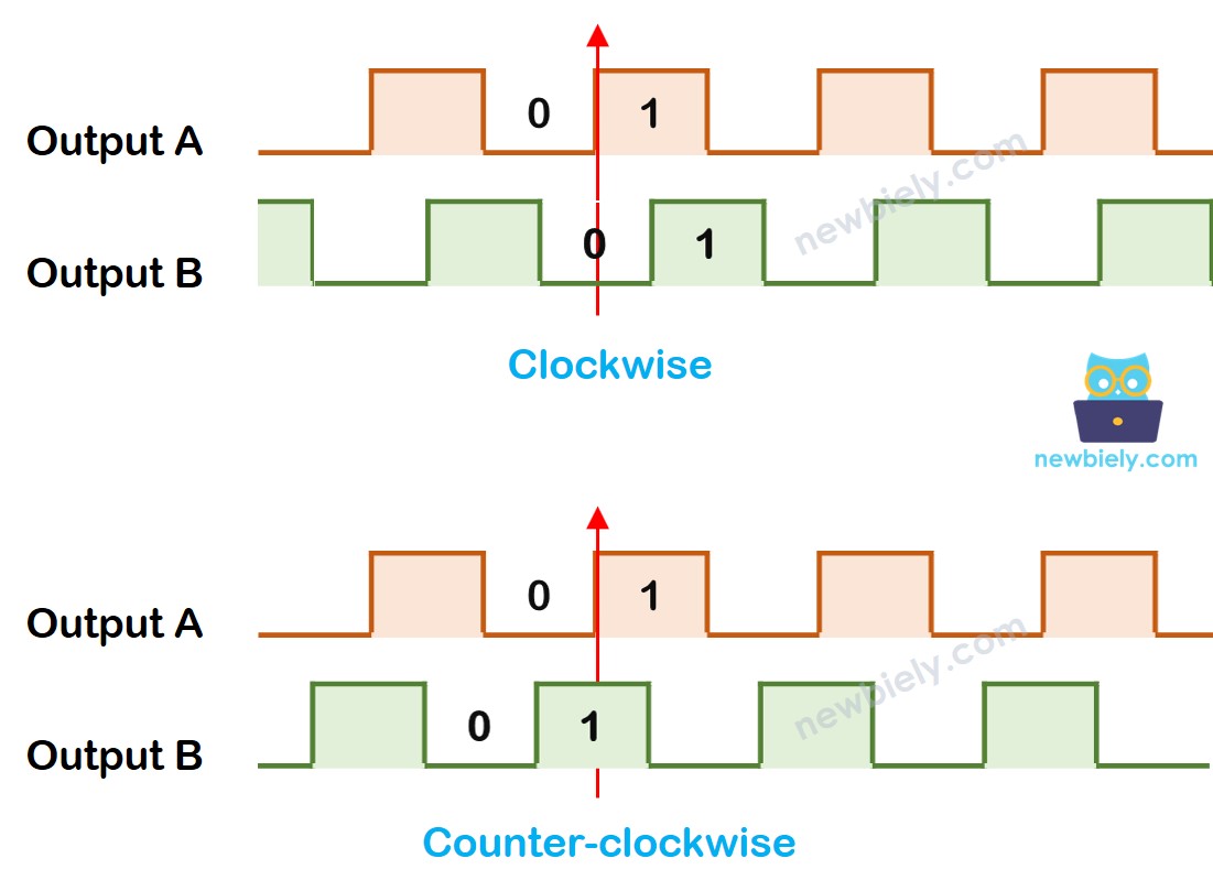
Direction detection logic:
When pin A changes from LOW to HIGH:
- If pin B is HIGH: Knob turned counter-clockwise
- If pin B is LOW: Knob turned clockwise
※ NOTE THAT:
Pins A and B connect to CLK and DT pins. Depending on the manufacturer, the order may vary. The code below is tested with DIYables rotary encoders.
How To Program For Rotary Encoder
Basic ESP32 C3 Super Mini encoder reading process:
- ESP32 reads the signal from the CLK pin continuously
- When CLK state changes from LOW to HIGH, ESP32 immediately reads the DT pin state
- If DT pin is HIGH: Counter-clockwise rotation detected → increase counter by 1
- If DT pin is LOW: Clockwise rotation detected → decrease counter by 1
- This method tracks both direction and total rotation amount
Wiring Diagram
This diagram shows how to connect the rotary encoder to your ESP32 C3 Super Mini board.
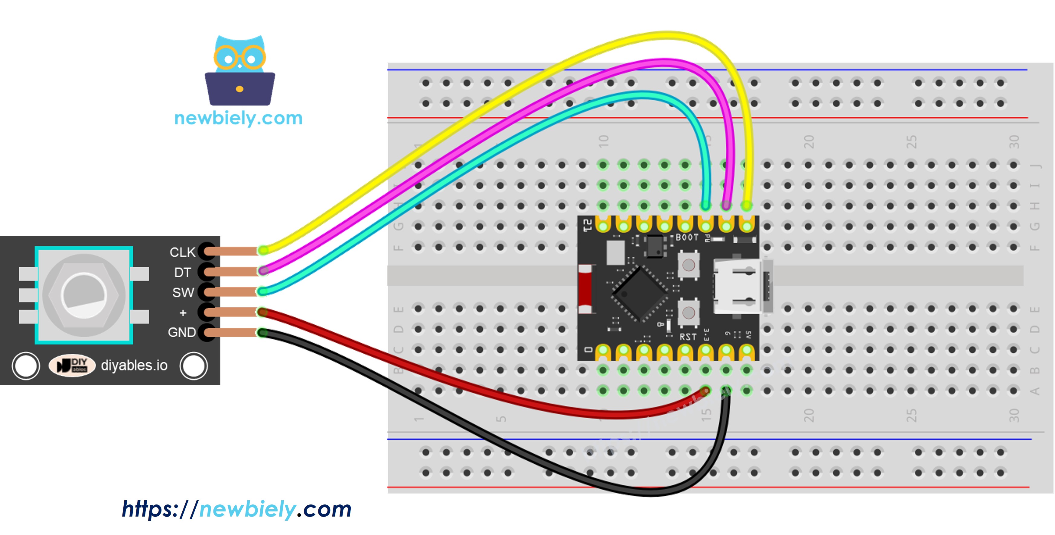
This image is created using Fritzing. Click to enlarge image
Connection Table:
| Rotary Encoder Pin | ESP32 C3 Super Mini Pin |
|---|---|
| CLK | D7 |
| DT | D6 |
| SW | D5 |
| VCC | 3.3V |
| GND | GND |
ESP32 C3 Super Mini Code – Rotary Encoder
This ESP32 C3 Super Mini code demonstrates basic rotary encoder functionality:
What this code does:
- Detects rotation direction (clockwise or counterclockwise)
- Counts rotation clicks by tracking detents
- Increases counter when rotated clockwise
- Decreases counter when rotated anticlockwise
- Detects button presses on the encoder knob
Note: This code uses the ezButton library to simplify button debouncing for reliable button press detection.
Detailed Instructions
- New to ESP32 C3 Mini? Complete our Getting Started with ESP32 C3 Mini tutorial first to set up your development environment.
- Install Library: Add the ezButton library through Arduino IDE Library Manager
- Open Code: Copy the code above and paste it into Arduino IDE
- Upload: Click the Upload button to transfer code to your ESP32 C3 Super Mini
- Test Rotation: Turn the encoder knob clockwise several clicks, then counterclockwise
- Test Button: Press down on the encoder knob
- View Results: Open Serial Monitor (115200 baud) to see rotation direction and count
- Pro Tip: Each "click" you feel when rotating is called a detent - the encoder outputs one complete pulse per detent
Serial Monitor Output:
Code Explanation
Review the detailed line-by-line comments in the code above to understand how each section works.
ESP32 C3 Super Mini Code – Rotary Encoder with Interrupt
The polling method in the previous code constantly checks pin states, which wastes ESP32 C3 Super Mini processing power and may miss rotation counts during slow code execution.
Why use interrupts for rotary encoders:
- Eliminates continuous polling - frees up ESP32 resources
- Never misses encoder pulses even during other tasks
- More efficient and reliable for real-world projects
- Allows ESP32 C3 Super Mini to multitask effectively
The code below uses hardware interrupts to read the rotary encoder direction and position efficiently:
When you turn the knob, the Serial Monitor displays the same rotation information as the previous example, but with improved performance.
※ NOTE THAT:
- One interrupt is enough: Many tutorials use two interrupts for one encoder, but this wastes resources - a single interrupt works perfectly
- Use volatile keyword: Always declare global variables used in interrupts as volatile to prevent unexpected behavior
- Keep interrupts simple: Minimize code inside interrupt functions - avoid using Serial.print() or Serial.println() in interrupts
- Fast execution: Interrupt code should execute as quickly as possible for best performance
ESP32 C3 Super Mini Rotary Encoder Application
Rotary encoders open up many exciting project possibilities for your ESP32 C3 Super Mini.
Popular rotary encoder project ideas:
- Control servo motor position precisely with encoder rotation
- Adjust LED brightness smoothly by turning the encoder knob
- Regulate stepper motor speed for robotics projects
- Create a digital volume control for audio systems
- Build a menu navigation system for OLED displays
- Design a smart thermostat with rotary temperature adjustment
- Make a rotary-controlled RGB LED color picker
Video Tutorial
Watch the video below for a visual walkthrough of this project.
Challenge Yourself
Test your skills by enhancing this ESP32 C3 Super Mini rotary encoder project.
Try these challenges:
- Easy: Add an LED that blinks when the encoder button is pressed
- Easy: Display the counter value on a 7-segment display instead of Serial Monitor
- Medium: Use the encoder to control servo motor angle (map counter to 0-180 degrees)
- Medium: Create a rotary-controlled LED brightness dimmer with PWM
- Advanced: Build a menu system on an LCD with encoder navigation and selection