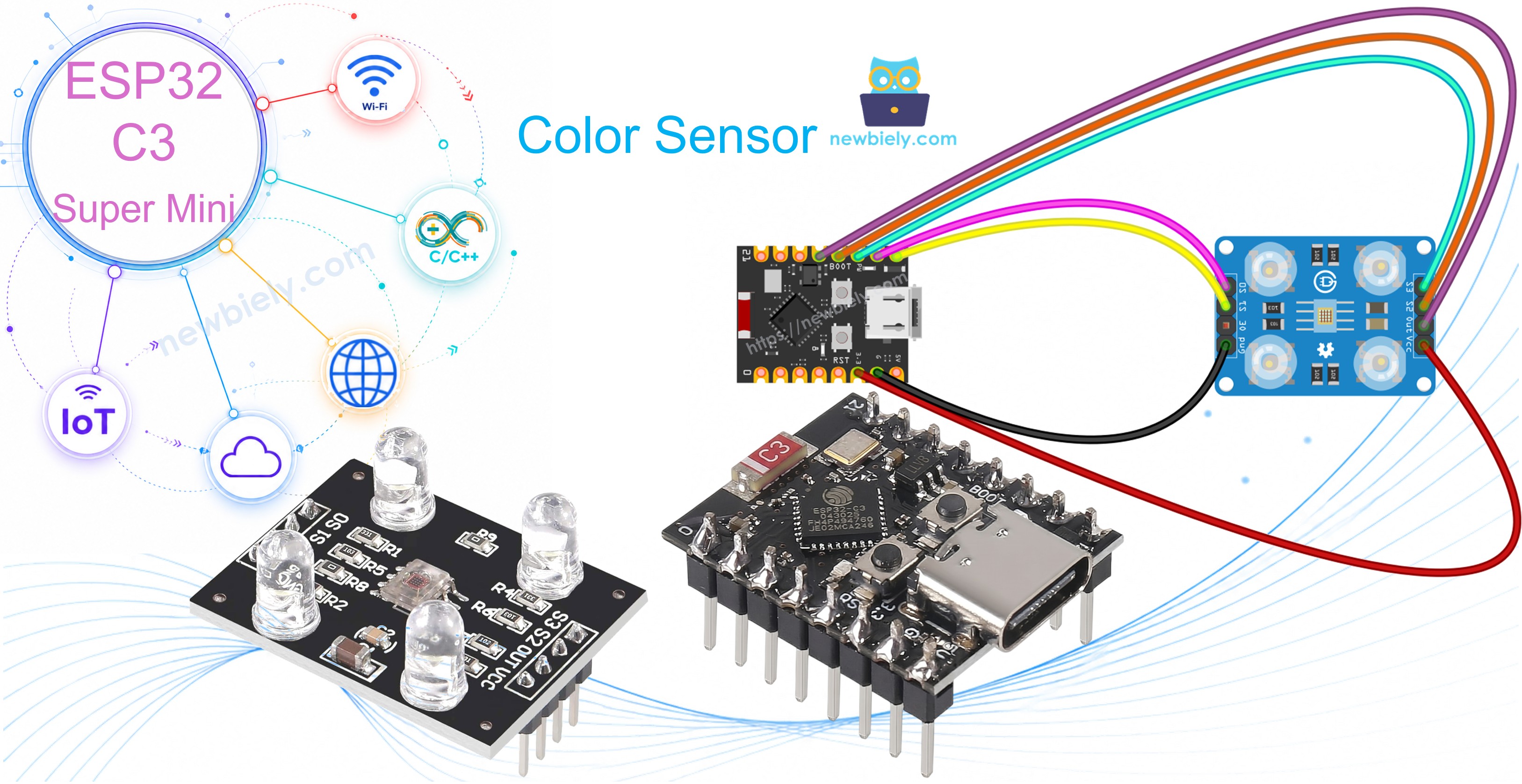
ESP32 C3 Super Mini - TCS3200D/TCS230 Color Sensor
Learn how to connect the TCS3200D/TCS230 color sensor to your ESP32 C3 Super Mini for accurate RGB color detection. This beginner-friendly tutorial covers calibration and real-time color measurements.
What you'll learn:
- What the TCS3200D/TCS230 color sensor is and how it detects colors
- How to wire the TCS3200 sensor to ESP32 C3 Super Mini
- How to calibrate the sensor for accurate readings
- How to read and display RGB color values
- Real-world applications for color sensing projects
Hardware Preparation
| 1 | × | ESP32 C3 Super Mini | |
| 1 | × | USB Cable Type-A to Type-C (for USB-A PC) | |
| 1 | × | USB Cable Type-C to Type-C (for USB-C PC) | |
| 1 | × | TCS3200D/TCS230 Color Recognition Sensor Module | |
| 1 | × | Breadboard | |
| 1 | × | Jumper Wires |
Or you can buy the following kits:
| 1 | × | DIYables Sensor Kit (18 sensors/displays) |
Additionally, some of these links are for products from our own brand, DIYables .
Overview of TCS3200D/TCS230 Color Sensor
The TCS3200D/TCS230 is an optical sensor that detects colors by measuring light reflections through specialized photodiode filters.
Key features:
- 64 photodiodes in 8×8 array (16 red filters, 16 green, 16 blue, 16 clear)
- Frequency output proportional to light intensity
- Operating voltage: 2.7V to 5.5V (5V recommended)
- Built-in white LED illumination for consistent readings
- Output frequency range: 2 Hz to 500 kHz
- Ideal for beginners: simple digital output, no complex analog reading
Why it's useful:
- Works in various lighting conditions thanks to onboard LEDs
- Easy to interface with ESP32 C3 Super Mini digital pins
- Perfect for color sorting, matching, and detection projects
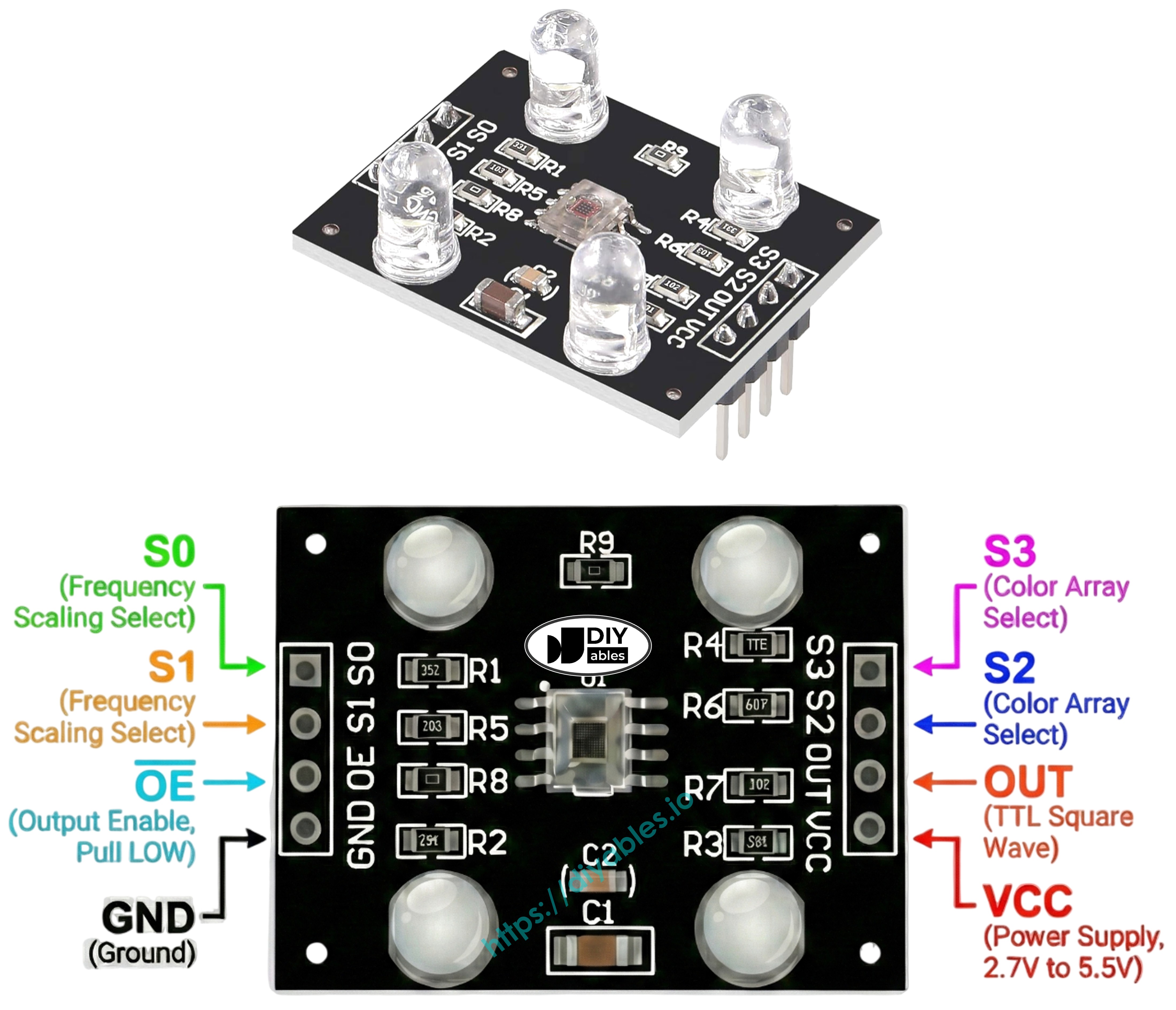
Pinout
The TCS3200D/TCS230 color sensor has 8 connection pins:
- VCC: Power supply input (connect to 5V)
- GND: Ground connection (0V reference)
- S0: Frequency scaling control pin 1
- S1: Frequency scaling control pin 2
- S2: Color filter selection pin 1
- S3: Color filter selection pin 2
- OUT: Frequency output signal pin (connect to ESP32 digital pin)
- OE: Output enable pin (active LOW, usually connected to GND)
How It Works
The TCS3200 color sensor operates using two control systems:
Frequency scaling (S0 and S1 pins):
- S0=LOW, S1=LOW: Power down mode
- S0=LOW, S1=HIGH: 2% frequency scaling
- S0=HIGH, S1=LOW: 20% frequency scaling
- S0=HIGH, S1=HIGH: 100% frequency scaling (recommended)
Color filter selection (S2 and S3 pins):
- S2=LOW, S3=LOW: Red filter active
- S2=LOW, S3=HIGH: Blue filter active
- S2=HIGH, S3=LOW: Clear filter (no filtering)
- S2=HIGH, S3=HIGH: Green filter active
How readings work:
- The OUT pin outputs a square wave signal
- Frequency increases with brighter light (2 Hz to 500 kHz)
- ESP32 C3 Super Mini measures pulse width using pulseIn()
- Shorter pulses = brighter light = higher color intensity
- Calibration converts pulse widths to standard RGB values (0-255)
Maximizing Measurement Precision
Follow these tips for accurate TCS3200 color readings:
- Keep sensor distance fixed at 1-3 cm from the object
- Position sensor at consistent angle (perpendicular works best)
- Use the built-in white LEDs for stable illumination
- Shield sensor from external light sources when possible
- Perform calibration in your actual working environment
- Test on flat, matte surfaces for best results
Wiring Diagram
Connect the TCS3200D color sensor to your ESP32 C3 Super Mini following this simple wiring configuration:
Safety note:
- Note: The TCS3200 sensor works best with 5V power, which the ESP32 C3 Super Mini can provide via the 5V pin when powered through USB.
| TCS3200 Color Sensor | ESP32 C3 Super Mini |
|---|---|
| VCC | 5V |
| GND | GND |
| S0 | D4 |
| S1 | D3 |
| S2 | D6 |
| S3 | D5 |
| OUT | D7 |
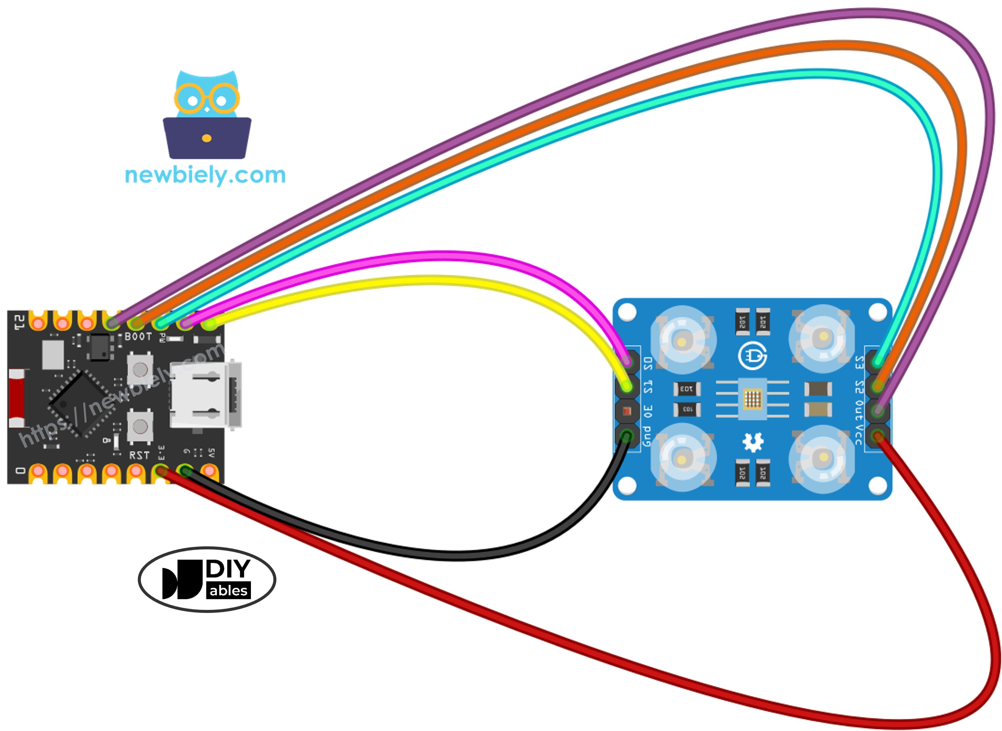
This image is created using Fritzing. Click to enlarge image
ESP32 C3 Super Mini Code - Sensor Calibration
Start with this calibration code to optimize your TCS3200 sensor for your specific environment.
What this code does:
- Powers up the sensor with full frequency scaling (100%)
- Cycles through red, green, and blue filters
- Tracks minimum and maximum pulse widths for each color
- Continuously updates calibration values as you show different colors
- Displays real-time measurements in the Serial Monitor
Detailed Instructions
- New to ESP32 C3 Mini? Complete our Getting Started with ESP32 C3 Mini tutorial first to set up your development environment.
- Wire the components: Follow the wiring diagram above to connect all pins correctly.
- Connect your board: Plug the ESP32 C3 Super Mini into your computer using a USB-C cable.
- Open Arduino IDE: Launch the software on your computer.
- Select your board: Choose ESP32 C3 Super Mini and the correct COM port from the Tools menu.
- Copy the code: Paste the calibration code into a new Arduino IDE sketch.
- Upload the code: Click the Upload button and wait for the process to complete.
- Open Serial Monitor: Set baud rate to 115200 to view calibration data.
- Point at white objects: Start with bright white paper or surfaces.
- Point at black objects: Move to dark black surfaces.
- Point at colored objects: Show the sensor various colored items (red, green, blue, yellow, etc.).
- Watch values stabilize: After 10-20 seconds, the Min/Max numbers will stop changing significantly.
- Record your values: Write down all six numbers (redMin, redMax, greenMin, greenMax, blueMin, blueMax).
- Pro Tip: Keep the sensor distance consistent (2-3 cm) during calibration for the most accurate results.
Calibration values from this example:
- RedMin = 38, redMax = 210
- GreenMin = 51, greenMax = 185
- BlueMin = 58, blueMax = 172
ESP32 C3 Super Mini Code - RGB Color Reading
Use this code to read accurate RGB color values after calibration.
What this code does:
- Applies your calibration values to normalize sensor readings
- Measures red, green, and blue channels sequentially
- Converts raw pulse widths to standard RGB format (0-255)
- Displays color values continuously in Serial Monitor
- Updates readings in real-time as you move colored objects
Detailed Instructions
- New to ESP32 C3 Mini? Complete our Getting Started with ESP32 C3 Mini tutorial first to set up your development environment.
- Locate calibration variables: Find these lines near the top of the code (around line 10-15):
- Insert your calibration values: Replace all zeros with the numbers you recorded during calibration. For example:
- Upload the code: Click Upload to transfer the modified code to your ESP32 C3 Super Mini.
- Open Serial Monitor: Set baud rate to 115200 to see RGB values.
- Test with colored objects: Place red, green, blue, yellow, or other colored items in front of the sensor.
- Read RGB values: Watch the color measurements update in real-time on the Serial Monitor.
- Pro Tip: For consistent results, always maintain the same distance and lighting conditions you used during calibration.
Understanding the output:
- Values range from 0 (no color detected) to 255 (maximum intensity)
- Higher numbers mean more of that color is reflected
- First three lines show a red object (high red value, low green/blue)
- Middle three lines show a green object (high green value)
- Last three lines show a blue object (high blue value)
Project Applications
Build creative color-sensing projects with your ESP32 C3 Super Mini and TCS3200 sensor:
- Automated color sorter: Sort M&Ms, LEGO bricks, or beads by color using a servo mechanism
- Color matching game: Challenge users to find objects matching a target RGB value
- Line-following robot: Create a robot that follows colored tape paths on the floor
- Quality control system: Detect defective products by comparing colors to reference standards
- Smart lighting controller: Automatically adjust RGB LED colors to match detected ambient colors
- Paint color identifier: Build a handheld device that identifies paint colors for home decorating
- Educational color mixer: Demonstrate additive color theory by displaying RGB values of mixed colors
Video Section
Watch the video below for a visual walkthrough of this project.
Challenge Yourself
Expand your TCS3200 color sensor skills with these project challenges:
- Easy: Add an RGB LED that lights up with the same color the sensor detects
- Easy: Display color names ("Red", "Green", "Blue") instead of just numbers when primary colors are detected
- Medium: Build a color memory game that shows random colors and tests if users can match them
- Medium: Create a color-based security system that only unlocks when shown a specific colored object
- Advanced: Build a full color sorter with servo motors that physically separate objects into bins by color
- Advanced: Develop a smartphone app that receives RGB values from ESP32 C3 Super Mini via Bluetooth and displays the actual color on screen