
Raspberry Pi Pico - MAX6675 Thermocouple Module
Every other temperature sensor covered on this site - the DS18B20, the DHT11, the LM35 - stops being useful well below the boiling point of water, and none of them would survive being clipped onto a soldering iron or dipped into melted wax. Once a project needs to see past a couple hundred degrees, the usual fix is a thermocouple probe read through a MAX6675 digitizer chip. There is no Arduino-style Library Manager to lean on here, so this tutorial reads the MAX6675 the way it is genuinely done in MicroPython: by toggling its clock, chip-select, and data pins directly from Python.
In this guide, we will cover:
- What a thermocouple actually is and why it needs a helper chip like the MAX6675.
- How to wire a MAX6675 breakout and its Type-K probe to a Raspberry Pi Pico.
- How to bit-bang the MAX6675's 3-wire read protocol in MicroPython - no external library required.
- How to print live Celsius and Fahrenheit readings to Thonny's Shell.
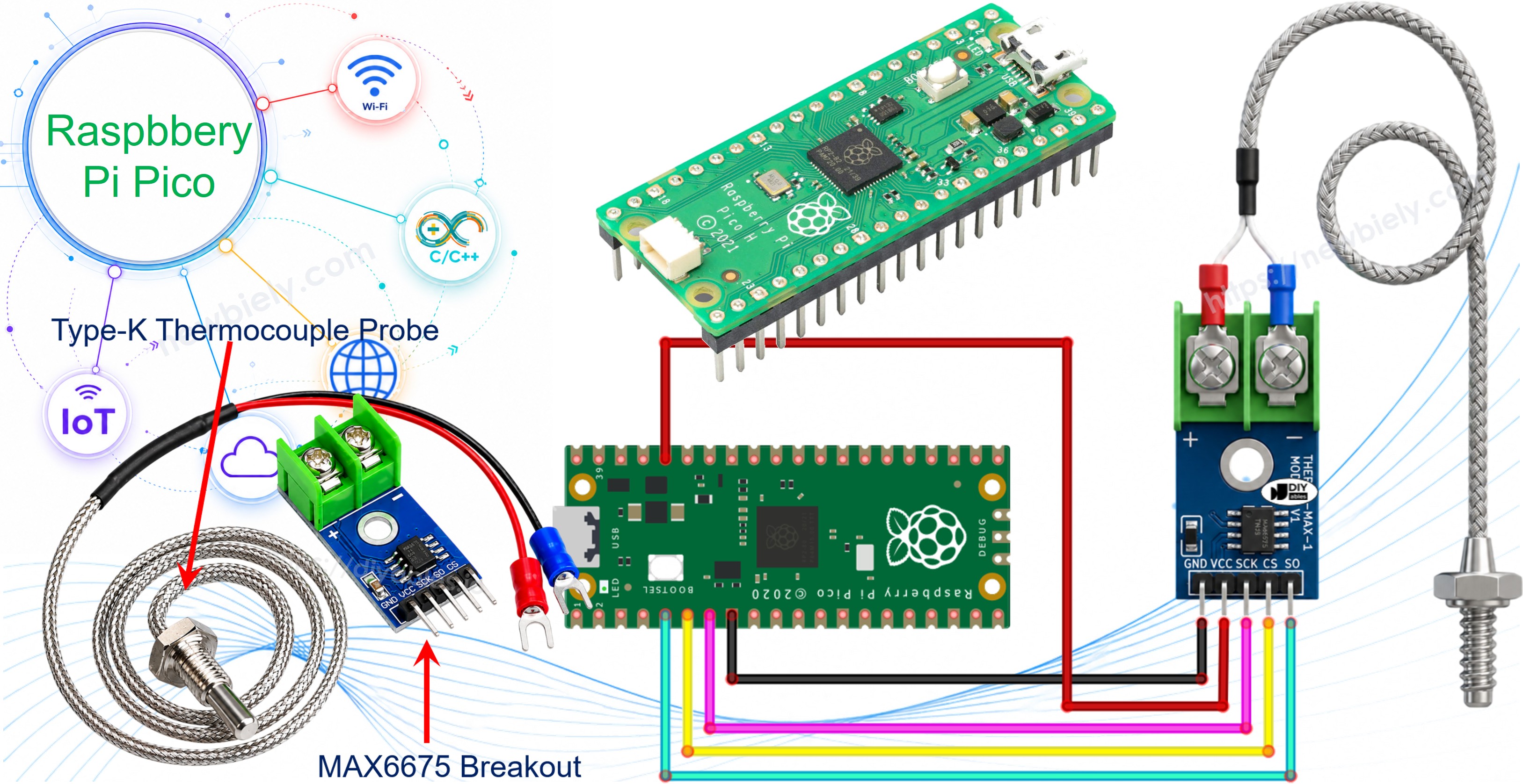
Hardware Preparation
Or you can buy the following kits:
| 1 | × | DIYables Sensor Kit (18 sensors/displays) |
Additionally, some of these links are for products from our own brand, DIYables .
What Is a Thermocouple?
A thermocouple is just two different metal wires fused together at one end, called the hot junction. Heat (or chill) that junction and a small voltage shows up across the wires, one that climbs or drops along with the temperature - which is why a thermocouple can shrug off conditions that would instantly kill a normal sensor. The most common flavor, Type-K, is built from Chromel and Alumel wire and is rated for roughly -328°F to +2300°F.
Overview of the MAX6675 Thermocouple Module
A bare thermocouple only outputs a few millivolts, far too small and noisy for the Pico to read on its own. The MAX6675 module solves that by pairing the MAX6675 chip on a small breakout board with a Type-K probe already attached, so the whole assembly hands back a clean, ready-to-use temperature reading.
| MAX6675 Thermocouple Module | |
|---|---|
| Operating Voltage | 3.0V to 5.5V |
| Measurable Range | 0°C to 1024°C |
| Accuracy | ±3°C |
| Resolution | ~0.25°C |
| Probe Length | ~18 inches (45 cm) |
| Probe Rating | 0°C to 80°C |
Pinout
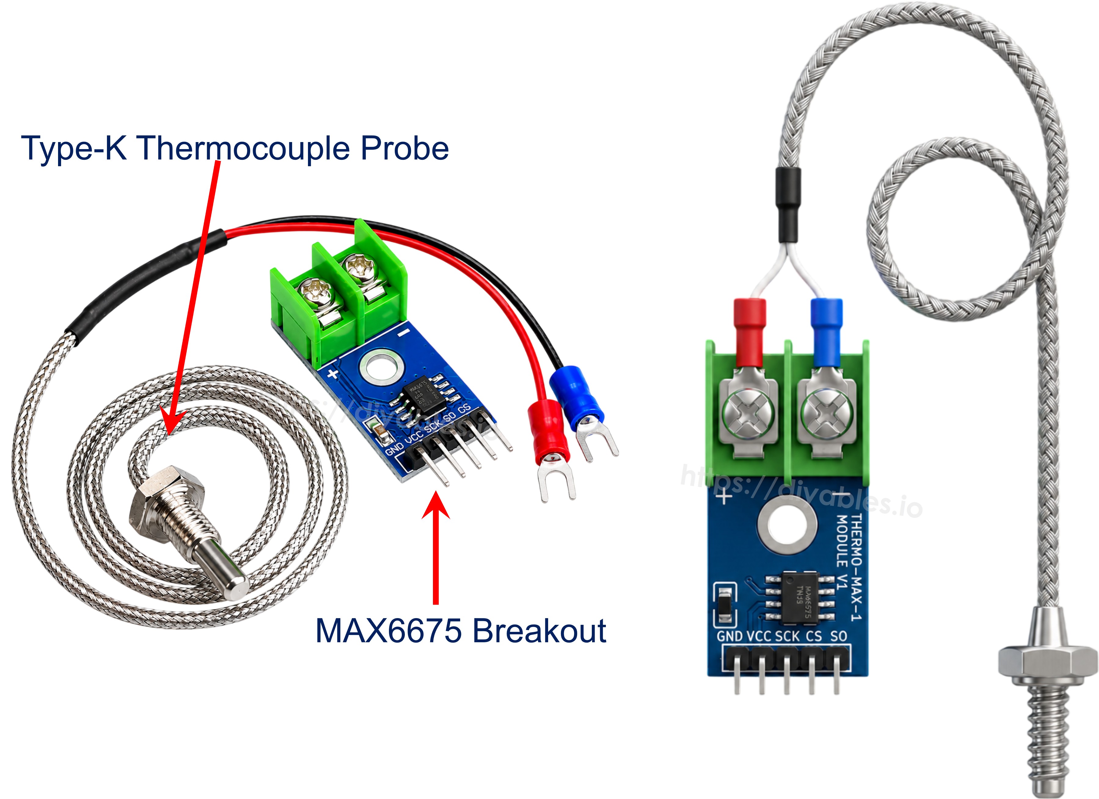
The breakout carries four header pins plus a 2-pin screw terminal where the probe attaches:
- VCC pin: power input, accepts 3.0V to 5.5V.
- GND pin: ground.
- SCK pin: serial clock input - the Pico pulses this to shift a reading out of the chip.
- CS pin: chip select - held LOW while a reading is being taken, HIGH the rest of the time.
- SO pin: serial data output - the only data line on the module, since it never receives commands from the Pico, only sends readings back.
- + / - terminal block: where the probe plugs in; its red lead goes to +, the blue lead to -.
The probe bundled with the module runs about 18 inches long, and even though the chip itself can digitize temperatures up to 1024°C, that particular probe wire is only rated for 0°C to 80°C - plan on a hotter-rated probe if you intend to point this at anything past a pot of boiling water.
Wiring Diagram
Power the module from the Pico's 3.3V rail rather than 5V, since the Pico's own GPIOs are 3.3V-only and are not 5V tolerant: VCC goes to 3V3(OUT) and GND goes to any GND pin. The three signal lines - SCK, CS, and SO - can land on whichever free GPIOs you like, because the code below bit-bangs them by hand instead of relying on the Pico's hardware SPI peripheral. Finish by seating the probe's red and blue leads into the module's + and - screw terminals.
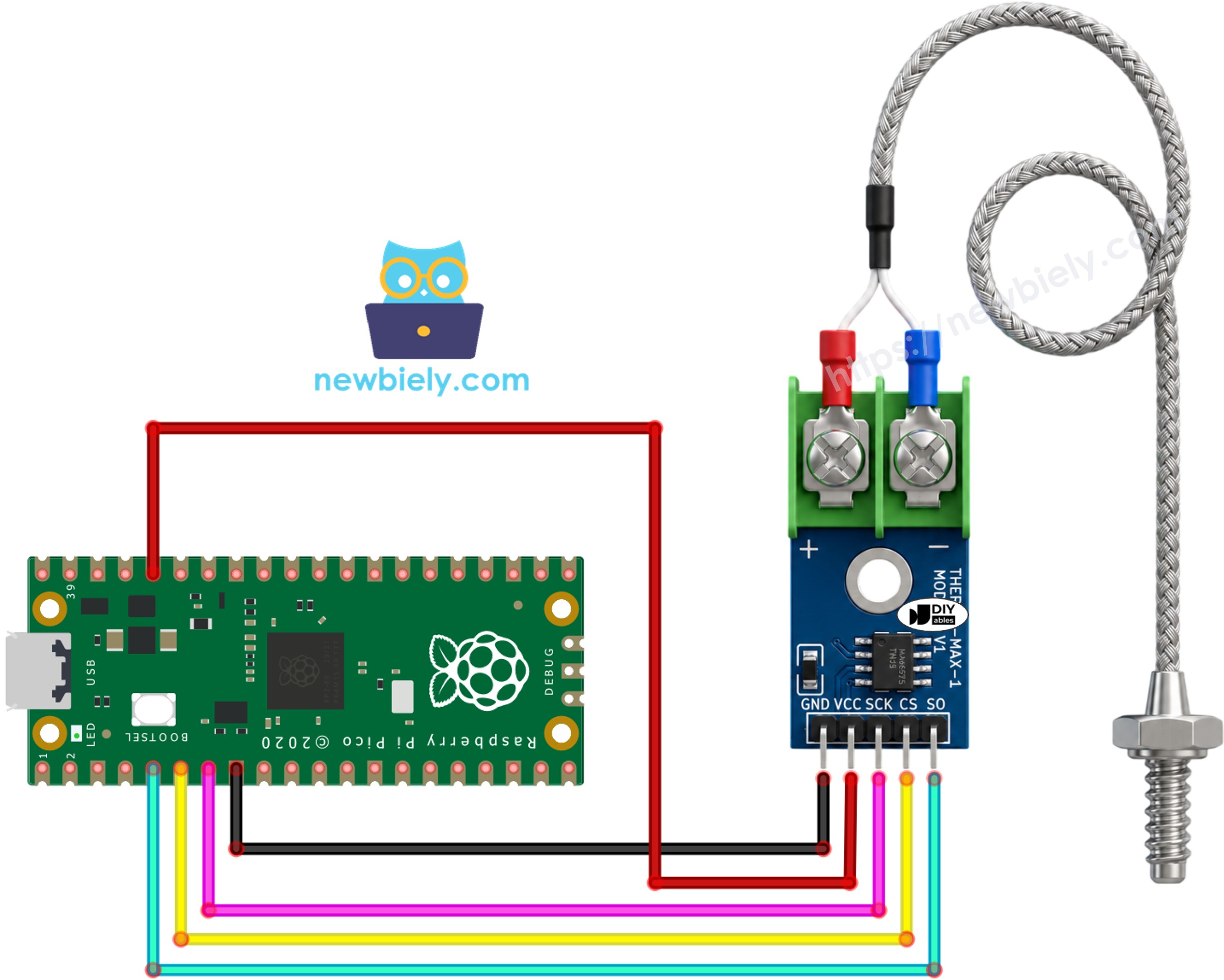
This image is created using Fritzing. Click to enlarge image
Raspberry Pi Pico - MAX6675 Module Wiring
| MAX6675 Module | Raspberry Pi Pico |
|---|---|
| VCC | 3V3(OUT) |
| GND | GND |
| SCK | GP5 |
| CS | GP4 |
| SO | GP3 |
Raspberry Pi Pico Code
Detailed Instructions
Please follow these instructions step by step:
- Ensure that Thonny IDE is installed on your computer.
- Ensure that MicroPython firmware is installed on your Raspberry Pi Pico.
- If this is your first time using a Raspberry Pico, refer to the Raspberry Pi Pico - Getting Started tutorial for detailed instructions.
- Wire the MAX6675 module and the thermocouple probe to the Raspberry Pi Pico following the diagram above.
- Connect the Raspberry Pi Pico to your computer using a USB cable.
- Launch the Thonny IDE on your computer.
- On Thonny IDE, select MicroPython (Raspberry Pi Pico) Interpreter by navigating to Tools Options.
- In the Interpreter tab, select MicroPython (Raspberry Pi Pico) from the drop-down menu.
- Ensure the correct port is selected. Thonny IDE should automatically detect the port, but you may need to select it manually (e.g., COM3 on Windows or /dev/ttyACM0 on Linux).
- Copy the above code and paste it to the Thonny IDE's editor.
- Save the script to your Raspberry Pi Pico by:
- Click the Save button, or use Ctrl+S keys.
- In the save dialog, you will see two sections: This computer and Raspberry Pi Pico. Select Raspberry Pi Pico
- Save the file as main.py
- Click the green Run button (or press F5) to run the script. The script will execute.
- Warm the thermocouple tip with your fingers, a cup of hot water, or a lighter held briefly nearby, then let it cool back down.
- Check out the message in the Shell at the bottom of Thonny.
If the probe is unplugged or wired wrong, the Shell prints "No thermocouple detected - check the probe connection" instead of a temperature - re-seat the red and blue leads in the screw terminal if you see that message.
If you name your script main.py and save it to the root directory of the Raspberry Pi Pico, it will automatically run each time the Pico is powered on or reset. This is useful for standalone applications that need to start running immediately upon power-up. If you name your script another name other than main.py, you will need to manually run it from Thonnys's Shell.
Code Explanation
Check the explanations in the source code comments! In short: the script pulls CS low, clocks SCK sixteen times while shifting whatever bit sits on SO into a 16-bit word, then raises CS again. The bottom 3 bits of that word are status bits (a set bit 2 means the probe is disconnected), so the code shifts them off and multiplies what remains by 0.25 to arrive at a temperature in Celsius, which is then converted to Fahrenheit for display.