
ESP32 C3 Super Mini - Potentiometer
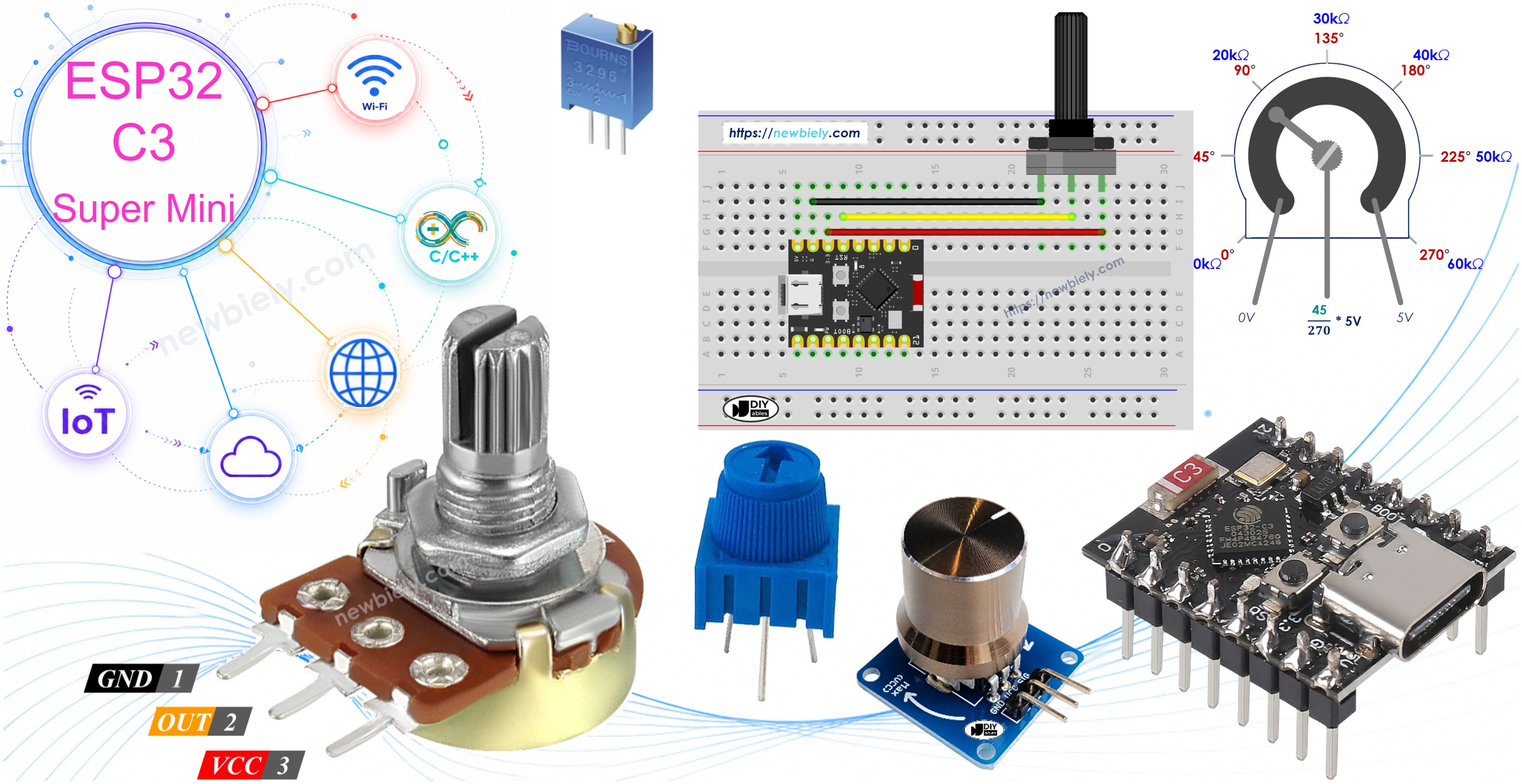
A potentiometer is the easiest way to add a control knob to your ESP32 C3 Super Mini project. Turn the knob, and the board reads a number you can use for volume, brightness, speed, or any other setting. It is a great first analog project for beginners.
In this tutorial, you'll learn:
- How a potentiometer works
- How to wire a potentiometer to the ESP32 C3 Super Mini
- How to program the ESP32 C3 Super Mini to read the potentiometer value
- How to convert that value into an angle, a voltage, or a setting value
- How to avoid the common mistakes beginners make with analog pins
Hardware Preparation
Or you can buy the following kits:
| 1 | × | DIYables Sensor Kit (18 sensors/displays) |
Additionally, some of these links are for products from our own brand, DIYables .
Overview of Potentiometer
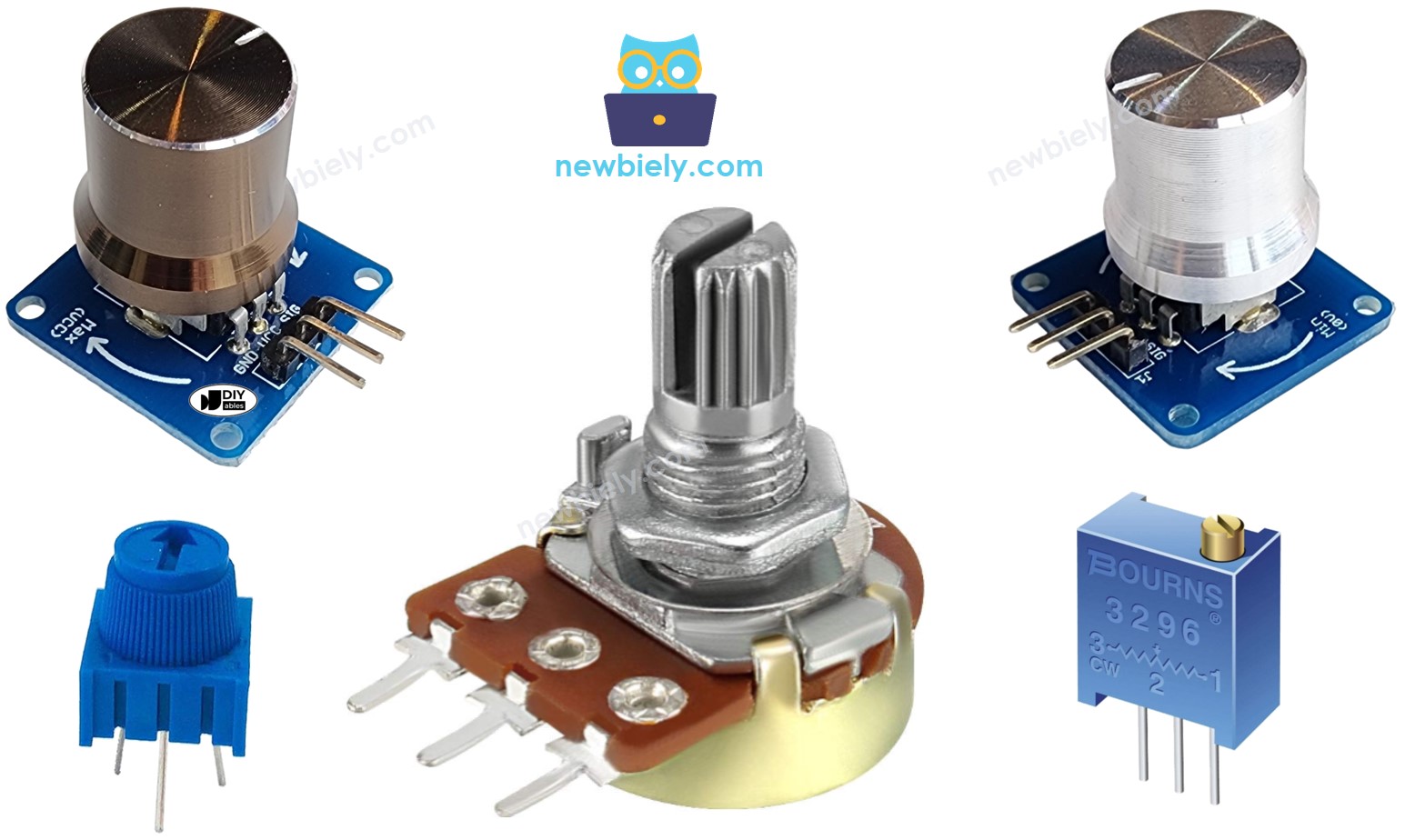
A potentiometer (also called a rotary angle sensor) is a knob that changes a setting, such as a speaker's volume, a room's temperature, or a lamp's brightness.
Key Features:
- Simple: Only 3 pins, no library needed.
- Cheap: One of the lowest cost parts you can buy.
- Analog output: Gives a smooth voltage, not just ON/OFF.
- No power hungry: Uses almost no current.
Technical Specifications:
- Working voltage: 3.3V or 5V (use 3.3V with the ESP32 C3 Super Mini)
- Output: 0V up to the voltage on the VCC pin
- Rotation: 0° to a maximum angle set by the maker
- Common values: 10kΩ is the most used
Potentiometer Pinout
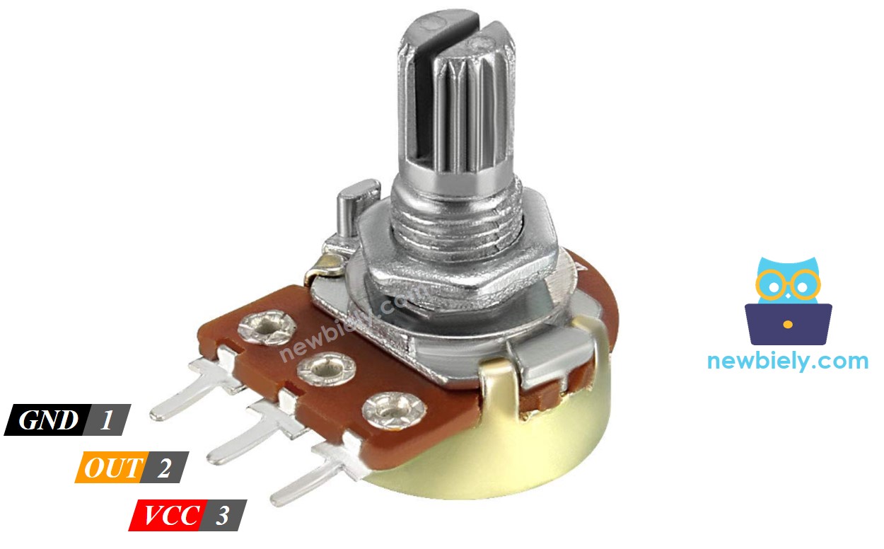
A potentiometer usually has 3 pins.
- VCC pin: connect this pin to VCC (3.3V on the ESP32 C3 Super Mini)
- GND pin: connect this pin to GND (0V)
- Output pin: outputs the voltage to the ESP32 C3 Super Mini's analog input pin
※ NOTE THAT:
The GND pin and VCC pin are interchangeable
WARNING
Always power the potentiometer from 3.3V, not 5V. The ESP32 C3 Super Mini GPIO pins are 3.3V only, and 5V on the output pin can damage the board.
How Potentiometer Works
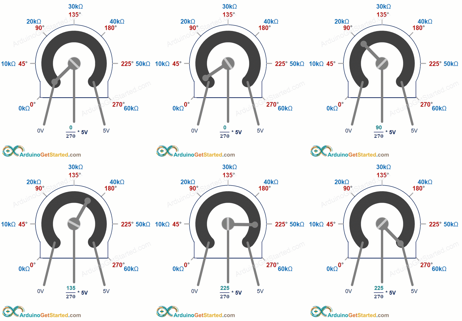
The shaft turns from 0° (closest to the GND pin) up to a maximum angle (closest to the VCC pin), called ANGLE_MAX.
- In short: more angle = more voltage on the output pin.
- The output voltage is in direct proportion to the shaft position, from 0 to VCC.
The table below shows the relation between the angle and the voltage on the output pin:
| Angle | Voltage |
|---|---|
| 0° | 0v |
| ANGLE_MAX° | VCC |
| angle° | angle° × VCC / ANGLE_MAX° |
※ NOTE THAT:
The ANGLE_MAX value is depended on manufacturers.
ESP32 C3 Super Mini - Rotary Potentiometer
The ESP32 C3 Super Mini's analog input pin turns a voltage into a number.
- Input range: 0V to 3.3V
- Output number: 0 to 4095 (this is called the ADC value or analog value)
- Resolution: 12-bit, so 4096 steps in total
- Analog pins on this board: GPIO0 to GPIO4 only. This tutorial uses GPIO4.
Connect the potentiometer's output pin to an ESP32 C3 Super Mini analog input pin, then read the analog value from that pin.
The analog value can be rescaled into another value. Here are the common use cases:
- To an angle: know how far the knob is turned.
- To a voltage: see the real voltage on the output pin.
- To a setting value: volume, temperature, brightness, motor speed, and so on.
Rescale Range
| FROM | TO | |||
|---|---|---|---|---|
| Angle | rotated by user | 0° | → | ANGLE_MAX° |
| Voltage | from potentiometer's pin | 0V | → | 3.3V |
| ADC value | read by ESP32 C3 Super Mini | 0 | → | 4095 |
| Setting value | converted by ESP32 C3 Super Mini | VALUE_MIN | → | VALUE_MAX |
Wiring Diagram between Potentiometer and ESP32 C3 Super Mini
The wiring is simple: two power wires and one signal wire.
- Note: Use the 3.3V pin for VCC. Never use 5V.
- Note: The signal wire goes to GPIO4, an analog-capable pin.
- Note: Do not use GPIO8 or GPIO9. They are strapping pins and can stop the board from booting.
- Note: GPIO20 and GPIO21 are the Serial Monitor UART. Keep them free.
| Potentiometer Pin | ESP32 C3 Super Mini Pin |
|---|---|
| VCC | 3.3V |
| GND | GND |
| Output | GPIO4 |
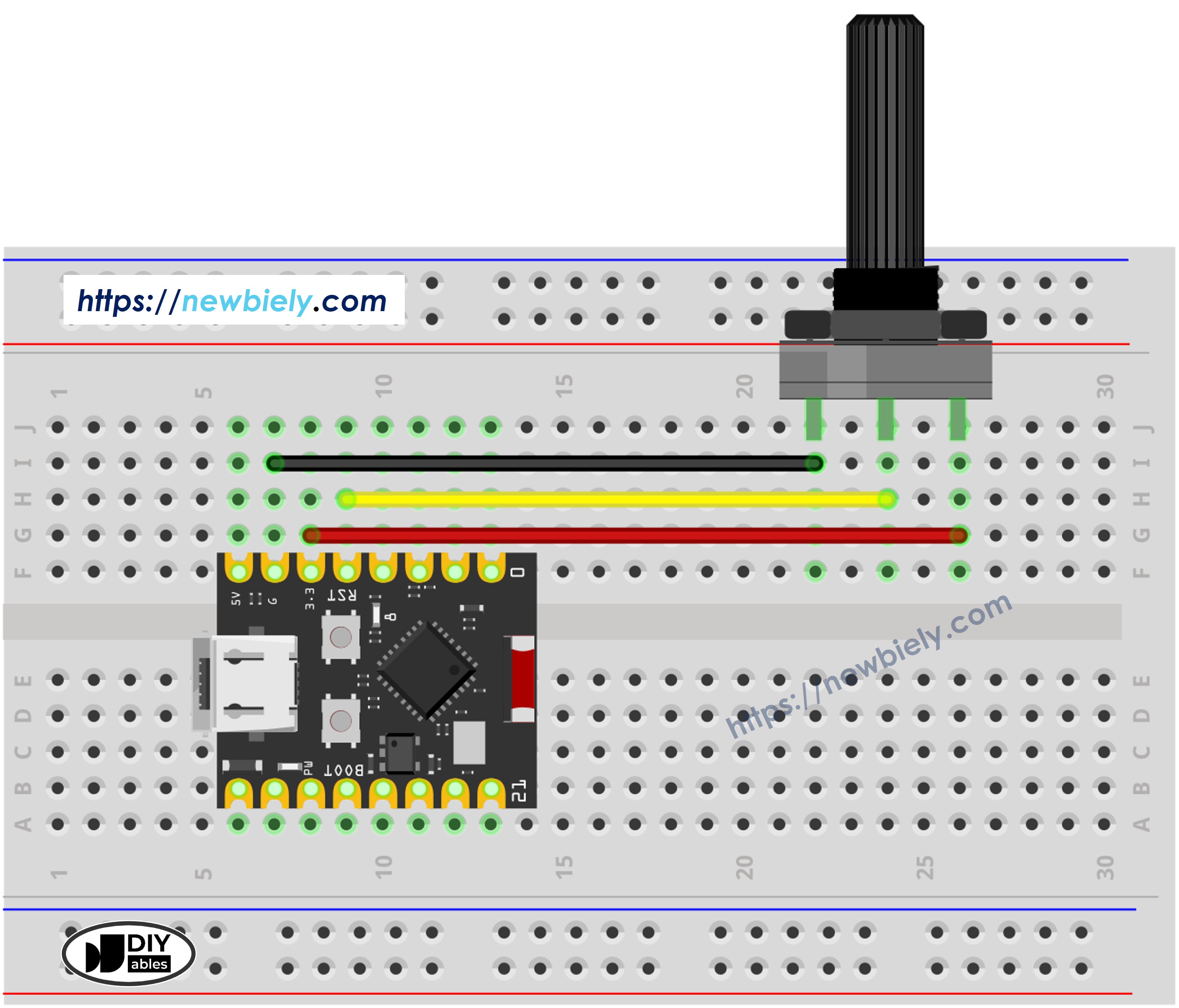
This image is created using Fritzing. Click to enlarge image
How To Program Potentiometer
Reading a potentiometer takes only one function, then a little math.
- Read the value from the analog input pin connected to the potentiometer's output pin by using the analogRead() function.
- Rescale to the potentiometer's angle by using the map() function.
- Rescale to the potentiometer's voltage:
- Rescale to the controllable value (e.g volume of stereo, brightness, speed of DC motor... )
- For example, rescaling to the brightness of an LED. As mentioned in this tutorial, the brightness of an LED can be controlled by using a PWM value from 0 (always OFF) to 255 (always ON). Therefore, we can map the analog value to the brightness of the LED (from OFF to the brightest) as follows:
If you want to dim the LED from a nightlight level to the brightest,
※ NOTE THAT:
Always use 4095 as the top of the input range, not 1023. The ESP32 C3 Super Mini has a 12-bit ADC. Code copied from an older 10-bit board often uses 1023 and will give wrong results on this board.
※ NOTE THAT:
The map() function can only be used to rescale the analog value to the int or long type value. If the controllable value is float type, you need to use the floatMap() function instead of the map() function.
floatMap() function:
ESP32 C3 Super Mini Code
The code below reads the potentiometer on GPIO4 and prints both the raw value and the voltage.
What This Code Does:
- Starts Serial: opens the Serial Monitor at 115200 baud.
- Sets the ADC: analogSetAttenuation(ADC_11db) lets the pin read the full 0V to 3.3V range.
- Reads the knob: analogRead() gives a number from 0 to 4095.
- Converts to volts: floatMap() turns that number into a voltage with decimals.
- Prints once a second: easy to follow while you turn the knob.
Detailed Instructions
- New to ESP32 C3 Super Mini? Complete our Getting Started with ESP32 C3 Super Mini tutorial first to set up your development environment.
- Wire it up: Connect the potentiometer to 3.3V, GND and GPIO4 as shown above.
- Connect the board: Plug the ESP32 C3 Super Mini into your computer with a USB Type-C cable.
- Open the IDE: Copy the code above and paste it into Arduino IDE.
- Select the board: Make sure ESP32 C3 Super Mini is selected in Tools > Board.
- Select the port: Pick the COM port of your board in Tools > Port.
- Upload: Click the Upload button on Arduino IDE.
- Open Serial Monitor: Set the baud rate to 115200.
- Turn the knob: Rotate the potentiometer slowly from one end to the other.
- Check the result: The Serial Monitor shows the value changing. It looks like the below:
- Pro Tip: If the value never reaches 0 or 4095, check that VCC and GND are firmly connected. A loose wire is the most common cause.
※ NOTE THAT:
This tutorial uses the analogRead() function to read values from an ADC (Analog-to-Digital Converter) connected to a sensor or component. The ESP32 C3 Super Mini's ADC is suitable for projects that do not require high accuracy. However, for projects needing precise measurements, keep the following in mind:
- The ESP32 C3 Super Mini's ADC is not perfectly accurate and might require calibration for correct results. Each ESP32 C3 Super Mini board can vary slightly, so calibration is necessary for each individual board.
- Calibration can be challenging, especially for beginners, and might not always yield the exact results you want.
For projects requiring high precision, consider using an external ADC (e.g ADS1115) with the ESP32 C3 Super Mini, or using another board with a more reliable ADC. If you still want to calibrate the ESP32 C3 Super Mini's ADC, refer to the ESP32 ADC Calibration Driver.
Project Ideas
Once the knob works, try using it to control something real.
- Dimmer Switch: Turn the knob to change the brightness of an LED.
- Volume Knob: Set the loudness of a buzzer or speaker.
- Servo Controller: Move a servo motor to the angle you choose.
- Motor Speed Dial: Change the speed of a DC motor or fan.
- Threshold Setter: Use the knob to set a sensor alarm level without editing code.
- Menu Selector: Scroll through options on an OLED or LCD screen.
Challenge Yourself
Try these small upgrades to learn more about analog input on the ESP32 C3 Super Mini.
- Easy: Print the value as a percentage from 0% to 100% instead of a raw number.
- Easy: Change the delay so the value updates 10 times per second.
- Medium: Map the value to an angle from 0° to 270° and print it.
- Medium: Average 10 readings before printing to make the value steady.
- Advanced: Use the knob to set the brightness of an LED on GPIO3 with PWM.
- Advanced: Add a second potentiometer on GPIO2 and read both knobs at the same time.