
Arduino Giga R1 WiFi IR Slotted Optical Speed Sensor
In this guide, we will learn how to use the IR slotted optical speed sensor with the Arduino Giga R1 WiFi. In detail, we will learn:
- What happens inside the U-shaped slot when a card or a disc tooth goes through it.
- How to power the sensor from the 3.3V pin of the Giga R1 WiFi and send its signal to pin 2.
- How to write a program for the Arduino Giga R1 WiFi that keeps a count of every object that enters the slot.
- How to write a program for the Arduino Giga R1 WiFi that turns encoder disc pulses into a speed value in RPM.
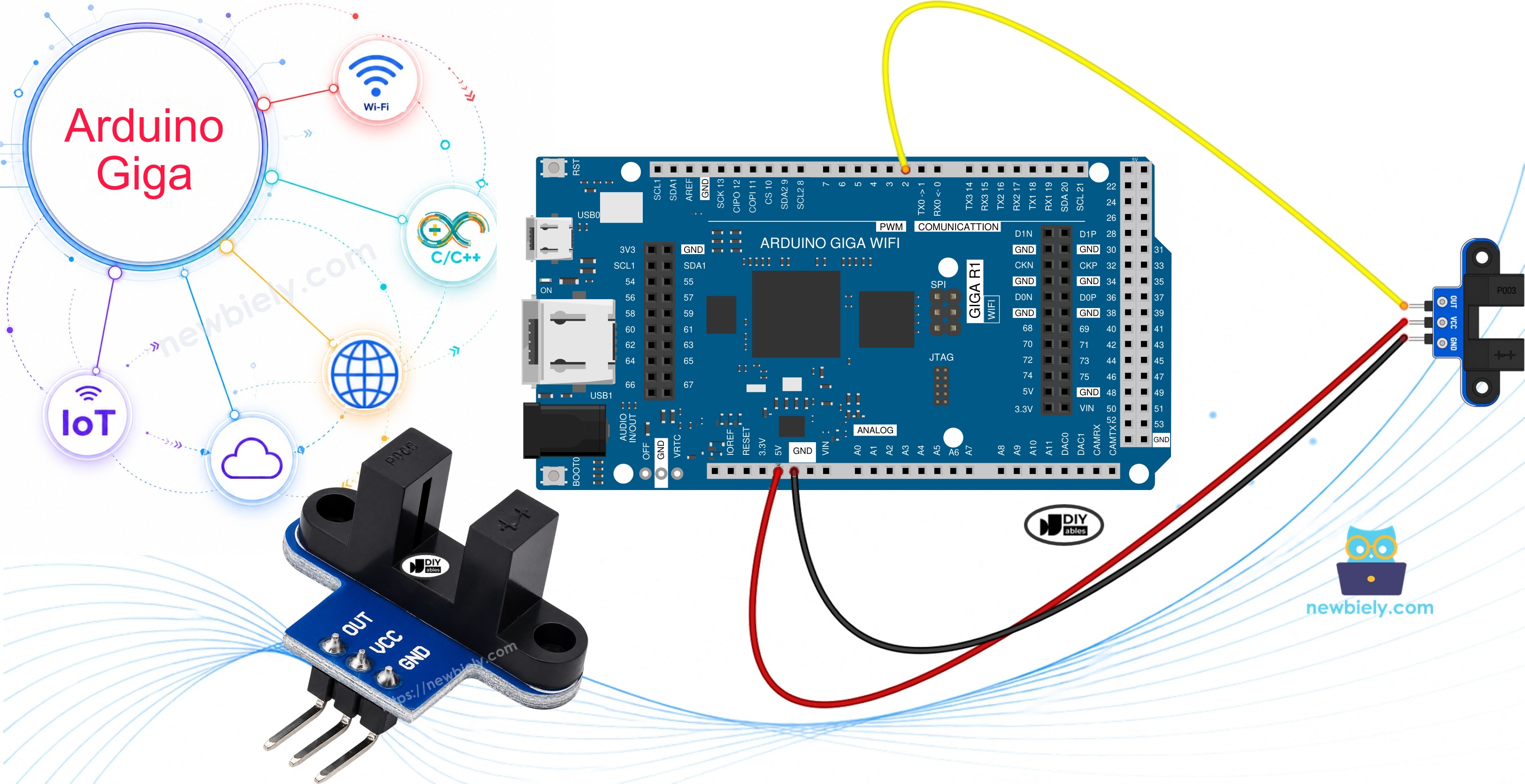
This page uses one sensor and one wheel. The Giga R1 WiFi has a large number of pins, though, so later you can add more sensors and watch the speed of several wheels with one board.
Hardware Preparation
Or you can buy the following kits:
| 1 | × | DIYables Sensor Kit (18 sensors/displays) |
Additionally, some of these links are for products from our own brand, DIYables .
Overview of IR Slotted Optical Speed Sensor
The sensor is a small fork with two arms and a narrow gap of 5.9 mm between them. An infrared LED is built into one arm. An NPN phototransistor is built into the opposite arm, so it looks straight at the LED. You may also see this part sold as a photo interrupter, an opto interrupter or a U-shaped IR sensor. All of these names mean the same module. Two M3 screw holes, one at each end, let you bolt it to a robot frame or a motor bracket.
| IR Slotted Optical Speed Sensor | |
|---|---|
| Sensor type | slot-type photoelectric (IR LED + NPN phototransistor) |
| Slot width | 5.9 mm |
| Operating voltage | 3.3V to 5V DC |
| Output | digital (TTL), LOW when blocked, HIGH when clear |
| Signal conditioning | built-in Schmitt trigger |
| Mounting | M3 screw holes at both ends |
| Pins | 3 (VCC, GND, OUT) |
How It Works

The LED sends an invisible beam across the gap, and the phototransistor waits on the other side. The OUT pin simply reports whether the beam gets through:
| What is in the slot | Beam | OUT pin |
|---|---|---|
| Nothing | reaches the phototransistor | HIGH |
| An opaque object (card, finger, disc tooth) | is cut off | LOW |
Between the phototransistor and the OUT pin, the module has a Schmitt trigger. Its job is to give a firm HIGH or a firm LOW, never a shaky value in between. That is why the code on this page has no debounce part, unlike a button.
The beam is infrared light, so a see-through object such as clear plastic may not stop it. For a reliable result, pass something solid and not transparent through the slot.
Pinout
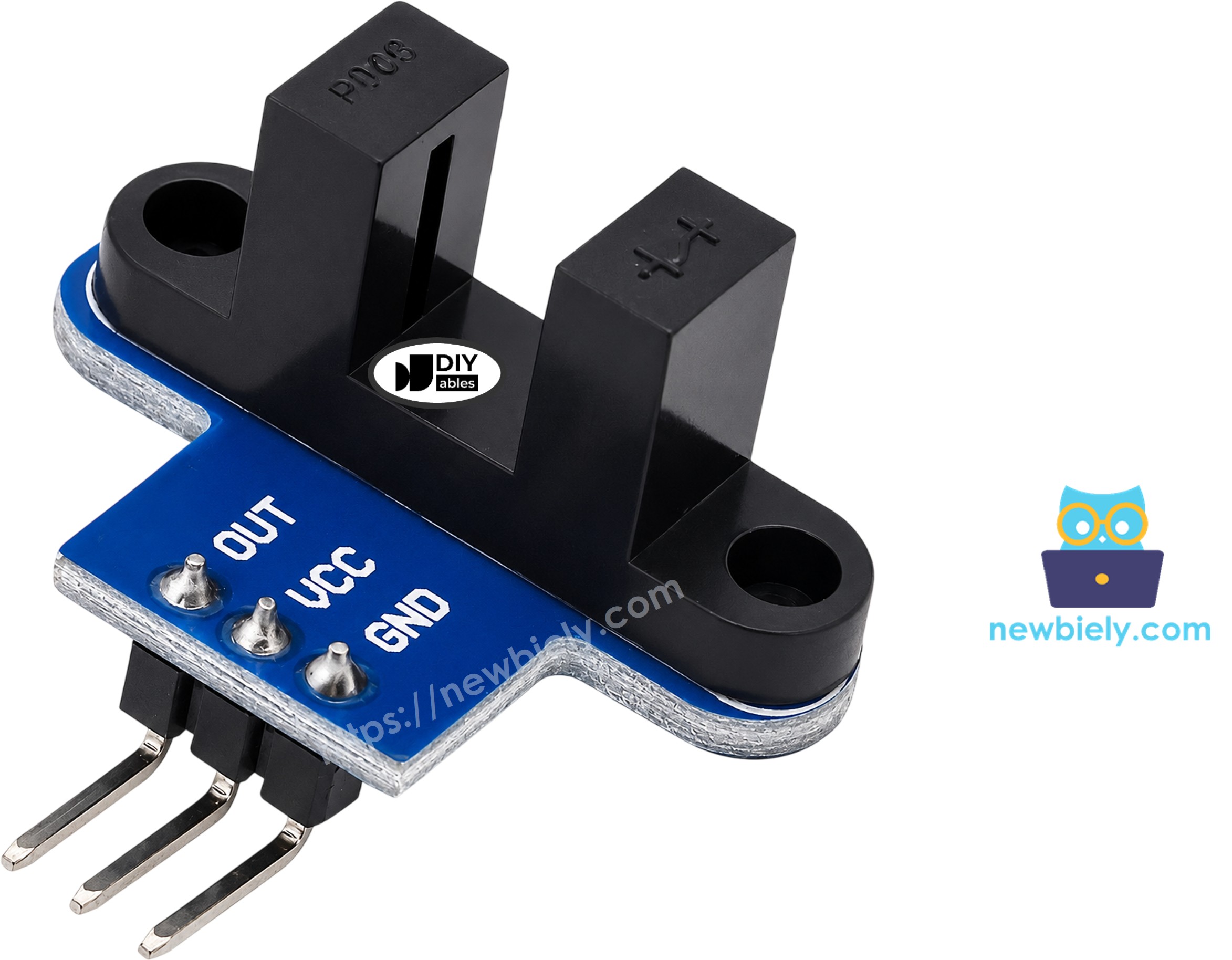
- GND pin: connect to GND (0V) of the Arduino Giga R1 WiFi.
- VCC pin: connect to the 3.3V pin of the Arduino Giga R1 WiFi (the module takes 3.3V to 5V).
- OUT pin: sends the digital result, connect to pin 2 of the Arduino Giga R1 WiFi.
Not every batch puts the three pins in the same order. Before you wire, look at the small labels on your own module.
Wiring Diagram
All Giga R1 WiFi pins work with 3.3V logic. The voltage on the OUT pin can go as high as the voltage you give to VCC. If you power the sensor from 3.3V, the signal on pin 2 stays at 3.3V or lower, which is safe for the board. So use the 3.3V header pin for VCC, not the 5V one.
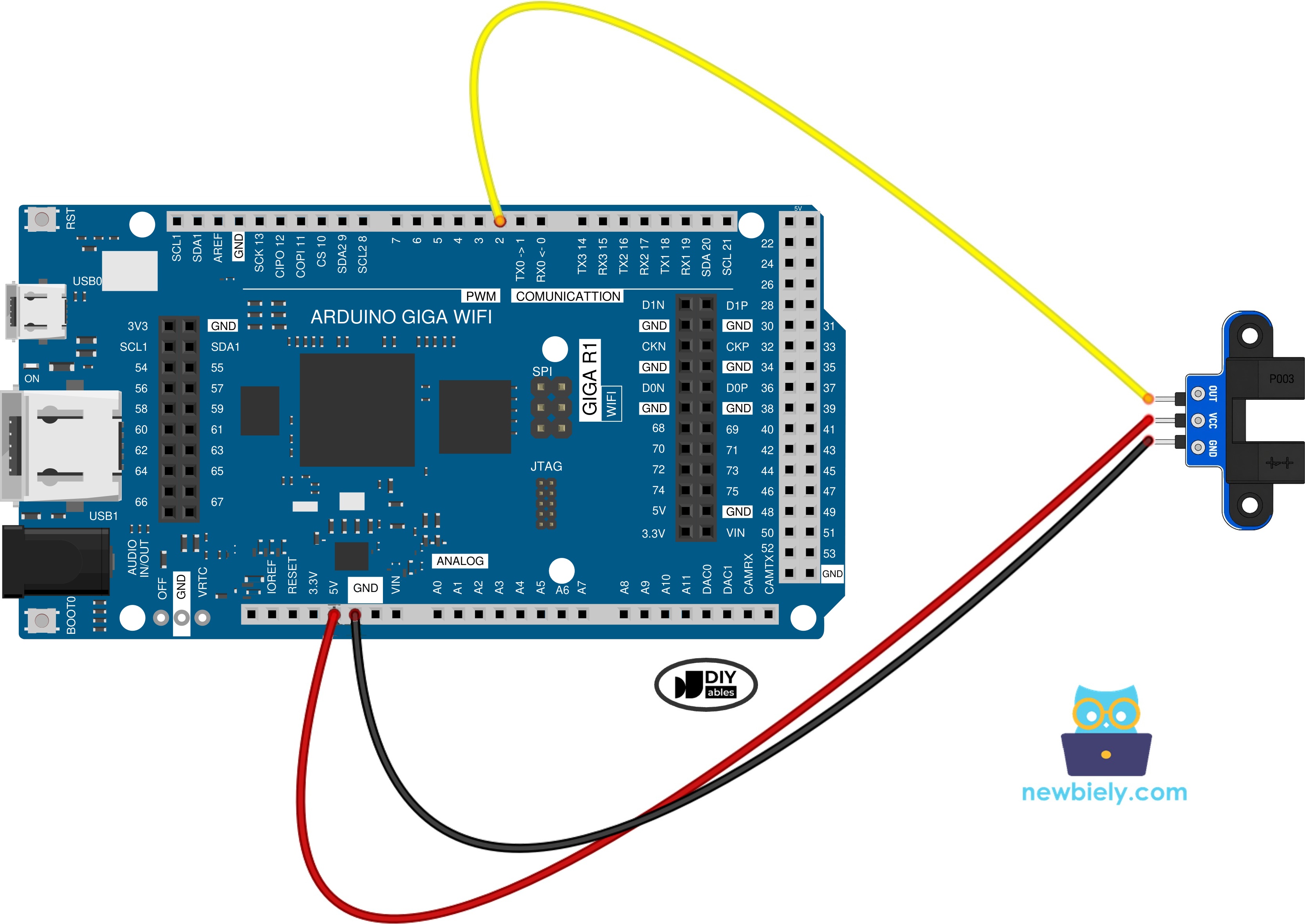
This image is created using Fritzing. Click to enlarge image
Pin 2 is our choice because it works with attachInterrupt(), and the speed program depends on that.
How To Program For IR Slotted Optical Speed Sensor
The two programs on this page read the sensor in two different ways.
Program 1 - check the pin yourself, inside loop():
- Set pin 2 as an input:
- Read the OUT signal. LOW tells you the beam is cut:
- React only to a change. When the new value is LOW, add one to the count:
Program 2 - let the board count for you, with an interrupt:
- Declare the pulse counter as volatile, because a function outside loop() changes it:
- Create the function that adds one pulse:
- Ask the board to call that function each time OUT goes from HIGH to LOW. This is the FALLING edge. It happens once for every tooth that enters the slot:
- Every 1000 ms, pause interrupts for a moment, copy the counter, set it to zero, and turn the interrupts back on. Pausing makes sure the counter does not change while you copy it:
- Change pulses into RPM:
The formula in plain words: a disc with 20 slots gives 20 pulses in one turn. The pulses from one second, times 60, are the pulses in one minute. Those divided by 20 are the turns in one minute, which is what RPM means.
Arduino Giga R1 WiFi Code - Object Counter
This program looks at pin 2 all the time, but it stays silent until the slot changes. When an object goes in, it adds one to the count and prints the new total. When the object leaves, it prints that the slot is clear.
Detailed Instructions
Follow these instructions step by step:
- Using the Giga R1 WiFi for the first time? Start with the Arduino Giga R1 WiFi getting started guide.
- Wire the components according to the provided diagram. VCC must go to 3.3V.
- Connect the Giga R1 WiFi to your computer through the USB Type-C cable.
- Launch the Arduino IDE on your computer.
- Select the appropriate Arduino Giga R1 WiFi board (e.g., Arduino Giga R1 WiFi) and COM port.
- Copy the code and put it into a new sketch.
- Hit the Upload button and wait until it finishes.
- Open the Serial Monitor and pick 9600 baud.
- Move a piece of thick paper down into the slot and lift it out again. Repeat this three times.
- See the output:
Do you see "blocked" while the slot is empty? Your module probably comes from another maker and uses the reverse logic. Swap LOW and HIGH in this program and it will be fine.
Prepare the Encoder Disc
The next program needs something that spins through the slot. An encoder disc is a thin wheel with a ring of holes, so its edge looks like a row of teeth.
- Slide the disc onto the motor shaft, or fix it to the wheel you want to measure.
- Hold the sensor so the toothed edge of the disc sits inside the slot.
- Give the disc a slow turn and check that it moves freely, without hitting either arm.
- Spin the disc by hand, or let the motor drive it. Motor wiring is not part of this page. For one way to run a motor from this board, see the Arduino Giga R1 WiFi - DC Motor Shield tutorial.
Arduino Giga R1 WiFi Code - Measure Rotation Speed (RPM)
When the disc spins fast, many teeth can go past while loop() is busy with other work. Checking the pin in loop() could lose some of them. So here the counting happens in an interrupt function, which runs right at the FALLING edge of each tooth. Once a second, the main program takes the count, shows it, and works out the RPM.
Near the top of the code you will find SLOTS_PER_TURN = 20. Twenty slots is what the usual encoder disc for TT gear motors has. If your disc has another number of holes, write that number here.
Detailed Instructions
- Leave the sensor wired to 3.3V, GND and pin 2.
- Put the RPM code into the Arduino IDE.
- Click Upload.
- Open the Serial Monitor at 9600 baud.
- Start the disc, keep it turning for a few seconds, then stop it.
- A new line shows up every second. This test ran close to 300 RPM:
Check the second line by hand: 98 × 60 ÷ 20 = 294 RPM. The 0 lines at the start and the end are the moments when the disc was still. Because this program counts one edge per tooth, it gives the right speed with both normal and reverse-logic modules.
Troubleshooting
| Problem | What to check |
|---|---|
| The count never changes | Is OUT on pin 2? Is the object solid, not clear plastic? |
| The board says "blocked" with an empty slot | Your module uses reverse logic. Swap LOW and HIGH in the object counter. |
| RPM looks too high or too low | Does SLOTS_PER_TURN match the holes on your disc? |
Two rules for the interrupt function: keep it very short, and never put Serial.print() inside it. Also, any variable it changes needs the volatile keyword.
Reading Several Wheels with the Giga R1 WiFi
A robot often has two or four wheels. With the many pins of the Giga R1 WiFi, you can give each wheel its own sensor:
- Wire each extra sensor the same way: VCC to 3.3V, GND to GND, OUT to a free pin. Make sure that pin works with attachInterrupt().
- For each sensor, make its own volatile counter and its own small counting function.
- Call attachInterrupt() once for each sensor in setup().
- In loop(), read and reset every counter inside the same noInterrupts() / interrupts() block, then work out the RPM of each wheel.
Project Ideas
- A tachometer that shows the RPM of a motor.
- Speed feedback for each wheel of a robot.
- A counter for parts, pulses or items that pass the slot.
- A distance meter: turns × wheel circumference (π × wheel diameter) gives how far a wheel has rolled.
- An end-stop or home-position check with no contact, as an option next to a limit switch.
To find an object at some distance instead of inside a narrow slot, try the ultrasonic sensor.