
Arduino Giga R1 WiFi DRV8833 DC Motor Driver
In this guide, we will learn how to use the DRV8833 motor driver with the Arduino Giga R1 WiFi to spin small DC motors in both directions at any speed. In detail, we will learn:
- What the DRV8833 does, and how its IN pins pick forward, reverse, coast and brake.
- How to hook up the Arduino Giga R1 WiFi, the DRV8833 module, a 5V adapter and one DC motor.
- How to write a program for the Arduino Giga R1 WiFi that ramps the motor up, lets it coast, reverses it and brakes it.
- How to add a second motor and move a two-wheel robot car forward, backward, left and right.
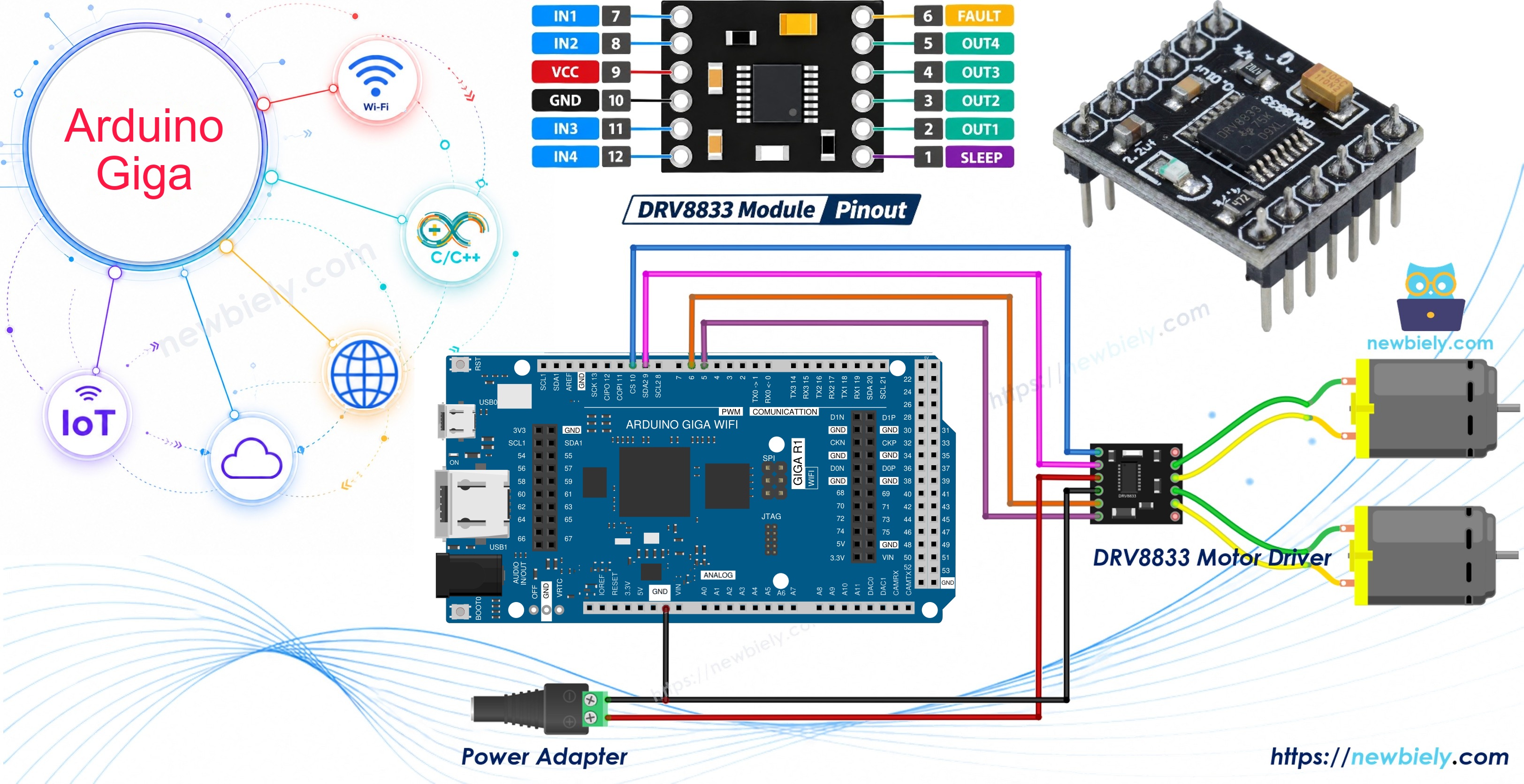
The Giga R1 WiFi runs its pins at 3.3V. Many older motor drivers want 5V signals, but the DRV8833 is happy with 3.3V. So you can wire it straight to the Giga, with no level shifter in between.
Hardware Preparation
Or you can buy the following kits:
| 1 | × | DIYables Sensor Kit (18 sensors/displays) |
Additionally, some of these links are for products from our own brand, DIYables .
You need the second motor only for Part 2.
Overview of DRV8833 Motor Driver
A pin of the Giga R1 WiFi can give only a few milliamps. A DC motor needs hundreds of milliamps, and it must be able to turn both ways. The DRV8833 from Texas Instruments sits in the middle. It has two H-bridges inside, so one small module controls two DC motors on their own. (It can also run one bipolar stepper motor, but this guide sticks to DC motors.)
Inside the chip, MOSFET switches do the work. They have a low resistance (about 360 mΩ for the high side and low side together), so they lose little voltage and stay cool. That is a big plus over the old L298N when you power a robot from 3V to 9V batteries.
| Feature | DRV8833 |
|---|---|
| Motor supply (VCC pin) | 2.7V to 10.8V |
| Logic supply | none needed, made inside the chip |
| Control signals | 3.3V or 5V |
| Output current | about 1.5A RMS per channel, 2A peak (with good cooling) |
| Number of DC motors | 2 |
| PWM frequency | up to 50 kHz |
| Protection | under-voltage lockout, over-current, thermal shutdown |
If one motor needs more current, you can join the two channels together for about 3A. That is an advanced setup, and we do not use it here.
Pinout
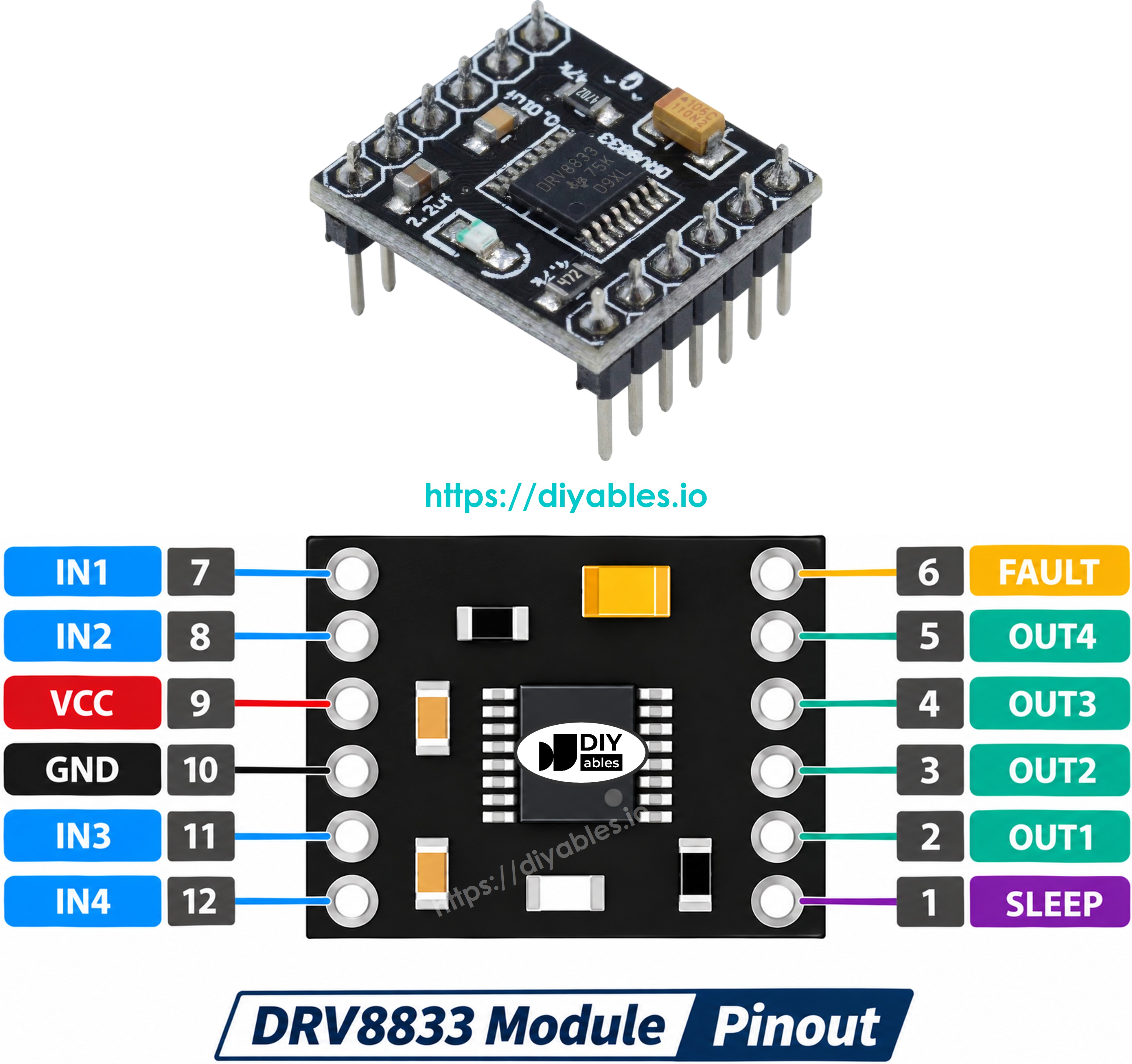
Control pins (to the Giga R1 WiFi):
- IN1, IN2 pins: control motor A. Connect to two PWM pins of the Giga.
- IN3, IN4 pins: control motor B. Connect to two more PWM pins of the Giga.
- EEP pin (sleep, also called nSLEEP or SLP): the driver works only when this pin is HIGH. Connect to the 3.3V pin of the Giga. LOW puts the chip to sleep.
- ULT pin (fault, also called nFAULT or FLT): goes LOW when the chip finds a problem. It is optional. You can leave it unconnected.
Power pins:
- VCC pin: connect to the motor power supply (2.7V to 10.8V), for example a 5V adapter.
- GND pin: connect to the ground of the motor supply and to a GND pin of the Giga.
Motor pins:
- OUT1, OUT2 pins: connect to the two wires of motor A.
- OUT3, OUT4 pins: connect to the two wires of motor B.
Labels vary between sellers. Some boards print AIN1, AIN2, BIN1, BIN2, AOUT1, AOUT2 and so on. Always follow the text on your own module.
How the IN Pins Control a Motor
The DRV8833 has no ENA or ENB speed pin like the L298N. Both direction and speed come from the two IN pins of each channel:
| IN1 | IN2 | Motor A does |
|---|---|---|
| LOW | LOW | Coast (no drive, the motor rolls to a stop) |
| HIGH | LOW | Forward |
| LOW | HIGH | Reverse |
| HIGH | HIGH | Brake (fast stop) |
Motor B works the same way with IN3 and IN4.
To set the speed, send PWM to one pin and hold the other LOW:
- Forward at part speed: PWM on IN1, IN2 LOW.
- Reverse at part speed: IN1 LOW, PWM on IN2.
So every IN pin must be a PWM pin. That is easy on the Giga: pins D2 to D13 all support analogWrite(). This guide uses D10, D9, D6 and D5.
PART 1: Control One DC Motor
Wiring Diagram
The Giga R1 WiFi sends only the control signals. The 5V adapter powers the motor through the VCC pin of the module.
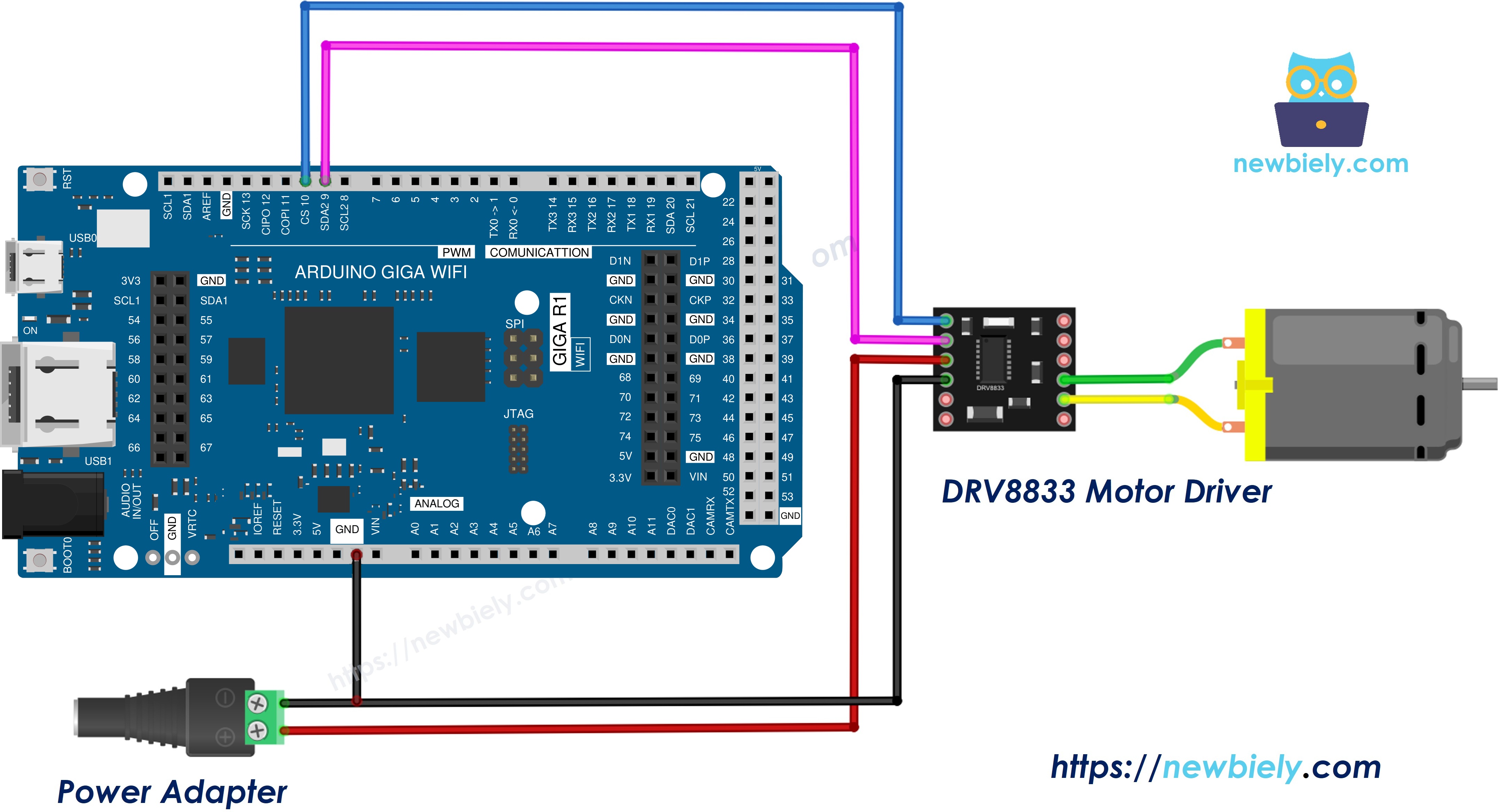
This image is created using Fritzing. Click to enlarge image
| DRV8833 Pin | Goes To |
|---|---|
| IN1 | Arduino Giga R1 WiFi pin D10 |
| IN2 | Arduino Giga R1 WiFi pin D9 |
| EEP | Arduino Giga R1 WiFi 3.3V |
| GND | Arduino Giga R1 WiFi GND and 5V adapter negative (via DC power jack) |
| VCC | 5V adapter positive (via DC power jack) |
| OUT1, OUT2 | The two wires of the DC motor |
| ULT | Not connected |
Important points:
- The adapter GND, the module GND and the Giga GND must all be joined. Without a shared ground, the IN signals have no reference and the motor will not move.
- Do not take motor power from the 5V or 3.3V pin of the Giga. A motor pulls large spikes of current that can reset or harm the board.
- If the motor turns the wrong way, swap its two wires on OUT1 and OUT2.
How To Program For DRV8833
The sketch needs no library. Only pinMode(), digitalWrite() and analogWrite() from the Arduino core.
- Choose the two PWM pins wired to IN1 and IN2:
- Set both pins as outputs:
- Spin forward at a speed from 0 to 255:
- Spin in reverse:
- Coast (free stop):
- Brake (fast stop):
The full sketch puts the first three cases into one helper, motorRun(speed). A positive speed means forward, a negative speed means reverse, and 0 means coast.
Arduino Giga R1 WiFi Code - One DC Motor
What the sketch does in each loop:
- Speeds up forward from 0 to 255, step by step.
- Holds full speed for 2 seconds.
- Coasts for 2 seconds.
- Runs in reverse at speed 180 for 2 seconds.
- Brakes for 2 seconds, then starts again.
Detailed Instructions
Follow these instructions step by step:
- New to this board? Set it up first with the Arduino Giga R1 WiFi getting started guide.
- Wire the components according to the provided diagram. Leave the 5V adapter unplugged for now.
- Plug the Giga R1 WiFi into your computer with the USB Type-C cable.
- Launch the Arduino IDE on your computer.
- Select the appropriate Arduino Giga R1 WiFi board (e.g., Arduino Giga R1 WiFi) and COM port.
- Paste the code above into a new sketch.
- Press the Upload button and wait until the upload is done.
- Plug in the 5V adapter.
- Open the Serial Monitor at 9600 baud.
- Watch the motor: it speeds up, runs fast, rolls to a stop, turns the other way, then stops sharply.
Notice the difference between "Coast" and "Brake". In coast mode the shaft keeps turning for a moment. In brake mode it stops almost at once.
The motor only hums at low speed? Small motors often need a speed value of about 60 to 80 before they start to turn. This is normal.
PART 2: Control Two DC Motors
Now we use the second channel too. Think of a small robot car: motor A drives the left wheel and motor B drives the right wheel.
Wiring Diagram
Keep the Part 1 wiring and add the second motor plus two more control wires.
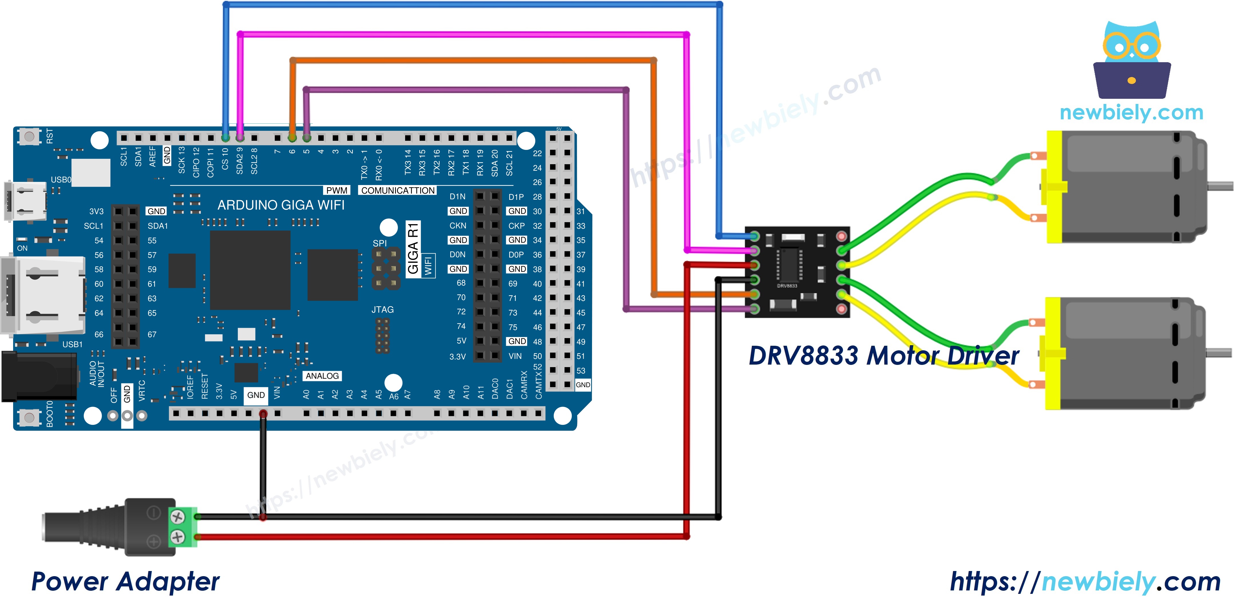
This image is created using Fritzing. Click to enlarge image
| DRV8833 Pin | Goes To |
|---|---|
| IN1 | Arduino Giga R1 WiFi pin D10 |
| IN2 | Arduino Giga R1 WiFi pin D9 |
| IN3 | Arduino Giga R1 WiFi pin D6 |
| IN4 | Arduino Giga R1 WiFi pin D5 |
| EEP | Arduino Giga R1 WiFi 3.3V |
| GND | Arduino Giga R1 WiFi GND and 5V adapter negative (via DC power jack) |
| VCC | 5V adapter positive (via DC power jack) |
| OUT1, OUT2 | Motor A (left wheel) |
| OUT3, OUT4 | Motor B (right wheel) |
Two motors draw about twice the current of one. Use an adapter that can give enough current for both, and remember the limit of about 1.5A per channel.
Arduino Giga R1 WiFi Code - Two DC Motors
The sketch has two helpers, motorA(speed) and motorB(speed). Each one takes a speed from -255 to 255. Turning is done by running the wheels in opposite directions:
- Turn left: motor A in reverse, motor B forward.
- Turn right: motor A forward, motor B in reverse.
Detailed Instructions
- Add the second motor and the IN3 and IN4 wires as shown in the diagram.
- Upload the new sketch with the 5V adapter unplugged.
- Plug in the adapter and open the Serial Monitor at 9600 baud.
- Watch both motors follow the forward, backward, left, right and stop pattern.
If one wheel turns the wrong way during "forward", swap the two wires of that motor only. You do not need to change the code.
Next step: the Giga R1 WiFi has built-in Wi-Fi and Bluetooth, so you can later send these drive commands from your phone. For a plug-on shield instead of a breakout module, see the Arduino Giga R1 WiFi - DC Motor Shield tutorial. For a motor that turns in one direction only, the Arduino Giga R1 WiFi - MOSFET Module tutorial is a simpler choice.