
ESP32 MicroPython 10 Segment LED Bar Graph
Or you can buy the following kits:
| 1 | × | DIYables ESP32 Starter Kit (ESP32 included) | |
| 1 | × | DIYables ESP32 S3 Starter Kit (ESP32 S3 included) | |
| 1 | × | DIYables Sensor Kit (18 sensors/displays) |
Additionally, some of these links are for products from our own brand, DIYables .
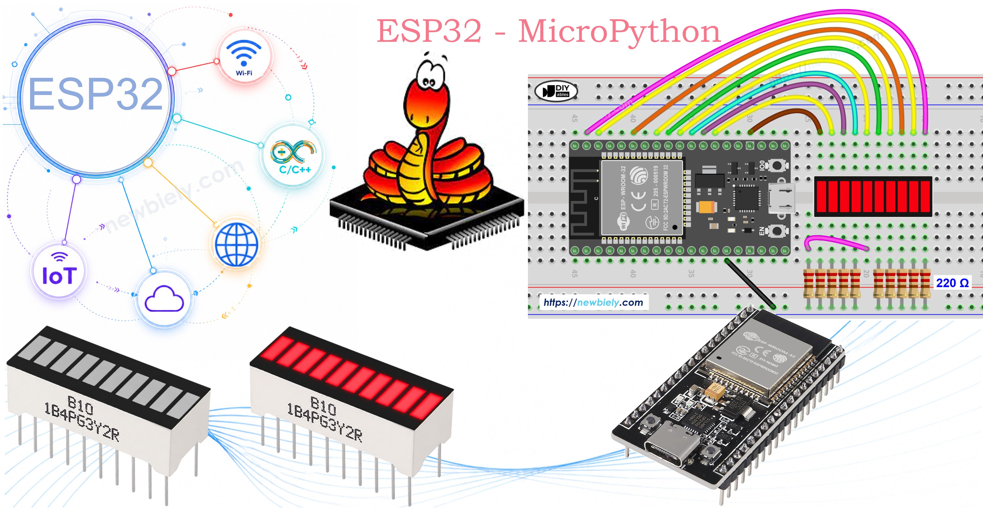
This tutorial instructs you how to use the 10 Segment LED Bar Graph with the ESP32 and MicroPython. In detail, we will learn:
- How to connect the 10 Segment LED Bar Graph to an ESP32.
- How to write MicroPython code for the ESP32 to animate the LED bar display.
Overview of 10 Segment LED Bar Graph
| 10 Segment LED Bar Graph | |
|---|---|
| Number of Segments | 10 |
| LED Color | Bright red |
| Forward Voltage | ~2V per segment |
| Forward Current | 20mA max per segment |
| Resistor Required | 220Ω per segment |
Pinout
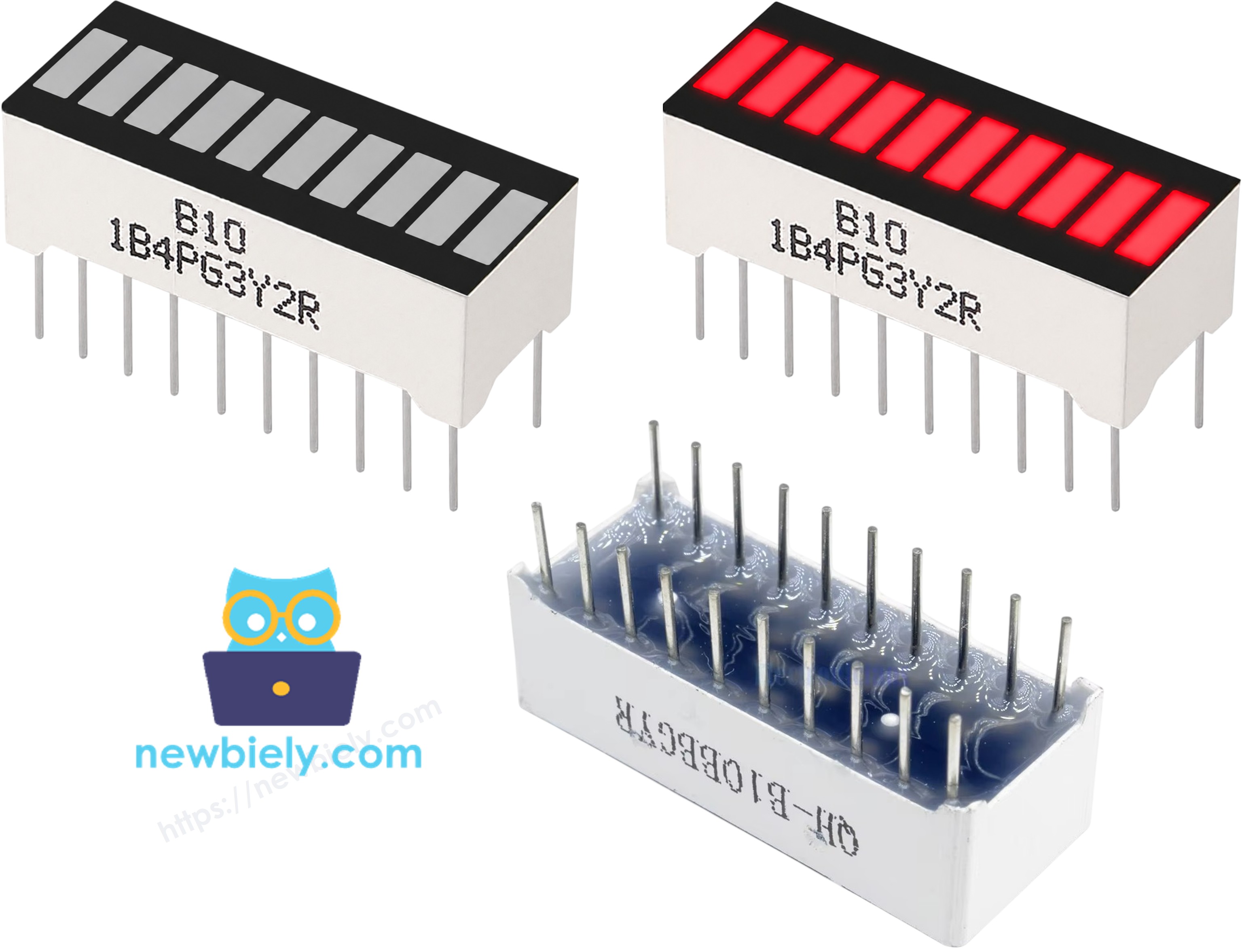
- Anode pins (A1–A10): connect to GPIO pins via 220Ω resistors
- Cathode pins (K1–K10): connect to GND (0 volts)
Wiring Diagram between 10 Segment LED Bar Graph and ESP32
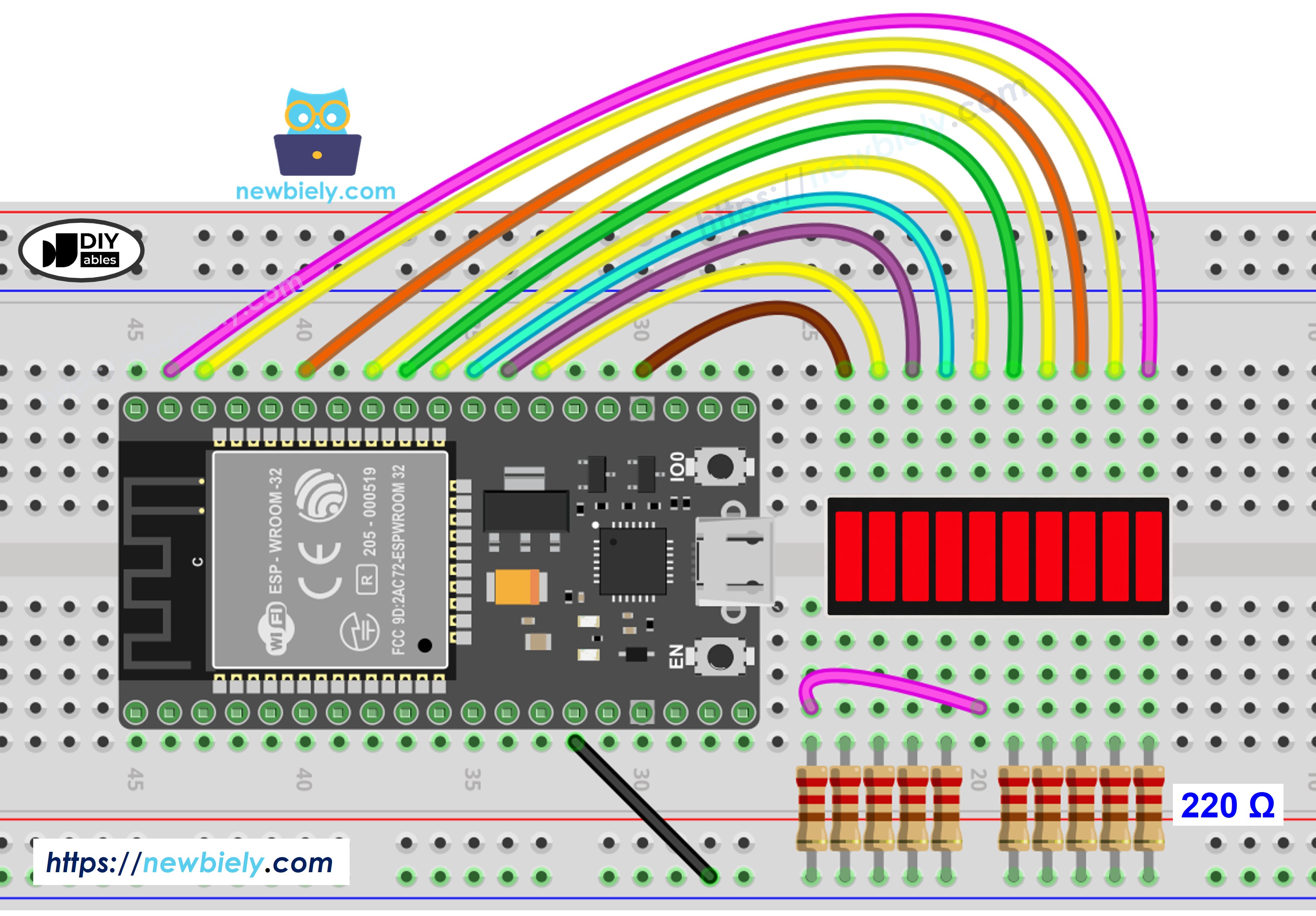
This image is created using Fritzing. Click to enlarge image
※ NOTE THAT:
All 10 anode pins are wired down a single side of the ESP32 Dev Board header, in physical pin order, to keep the wiring straightforward. This does mean GPIO5 and GPIO15 are used — both only briefly pulse at boot and are commonly used for onboard LEDs, so they're low-risk. GPIO0, GPIO2, and GPIO12, which can actually interfere with the board's boot or flashing mode, are avoided entirely.
| LED Bar Graph | ESP32 Pin |
|---|---|
| A1 (Anode 1) | GPIO23 (via 220Ω) |
| A2 (Anode 2) | GPIO22 (via 220Ω) |
| A3 (Anode 3) | GPIO21 (via 220Ω) |
| A4 (Anode 4) | GPIO19 (via 220Ω) |
| A5 (Anode 5) | GPIO18 (via 220Ω) |
| A6 (Anode 6) | GPIO5 (via 220Ω) |
| A7 (Anode 7) | GPIO17 (via 220Ω) |
| A8 (Anode 8) | GPIO16 (via 220Ω) |
| A9 (Anode 9) | GPIO4 (via 220Ω) |
| A10 (Anode 10) | GPIO15 (via 220Ω) |
| K1–K10 (Cathodes) | GND |
ESP32 MicroPython Code - 10 Segment LED Bar Graph
Here's instructions on how to set up and run your MicroPython code on the ESP32 using Thonny IDE:
- Make sure Thonny IDE is installed on your computer.
- Confirm that MicroPython firmware is loaded on your ESP32 board.
- If this is your first time, refer to the ESP32 MicroPython Getting Started guide.
- Connect the 10 Segment LED Bar Graph to the ESP32 according to the provided diagram.
- Connect the ESP32 to your computer with a USB cable.
- Open Thonny IDE.
- In Thonny, go to Tools → Options, Interpreter tab, and select MicroPython (ESP32) from the dropdown.
- Copy the provided MicroPython code and paste it into Thonny's editor.
- Save the code to your ESP32 by: choosing File → Save as..., selecting MicroPython device, and naming the file main.py.
- Click the green Run button (or press F5) to run the script.
- Watch the LED bar animate on your breadboard.
- Check the Shell at the bottom of Thonny for the printed bar output.
Thonny Console
If you name your script main.py and save it to the MicroPython device, it will run automatically every time the ESP32 is powered on.