
ESP32 C3 Super Mini - 10 Segment LED Bar Graph
Or you can buy the following kits:
| 1 | × | DIYables Sensor Kit (18 sensors/displays) |
Disclosure: Some of the links provided in this section are Amazon affiliate links. We may receive a commission for any purchases made through these links at no additional cost to you.
Additionally, some of these links are for products from our own brand, DIYables .
Additionally, some of these links are for products from our own brand, DIYables .
Learn how to use the 10 Segment LED Bar Graph with the ESP32 C3 Super Mini to create animated LED bar displays.
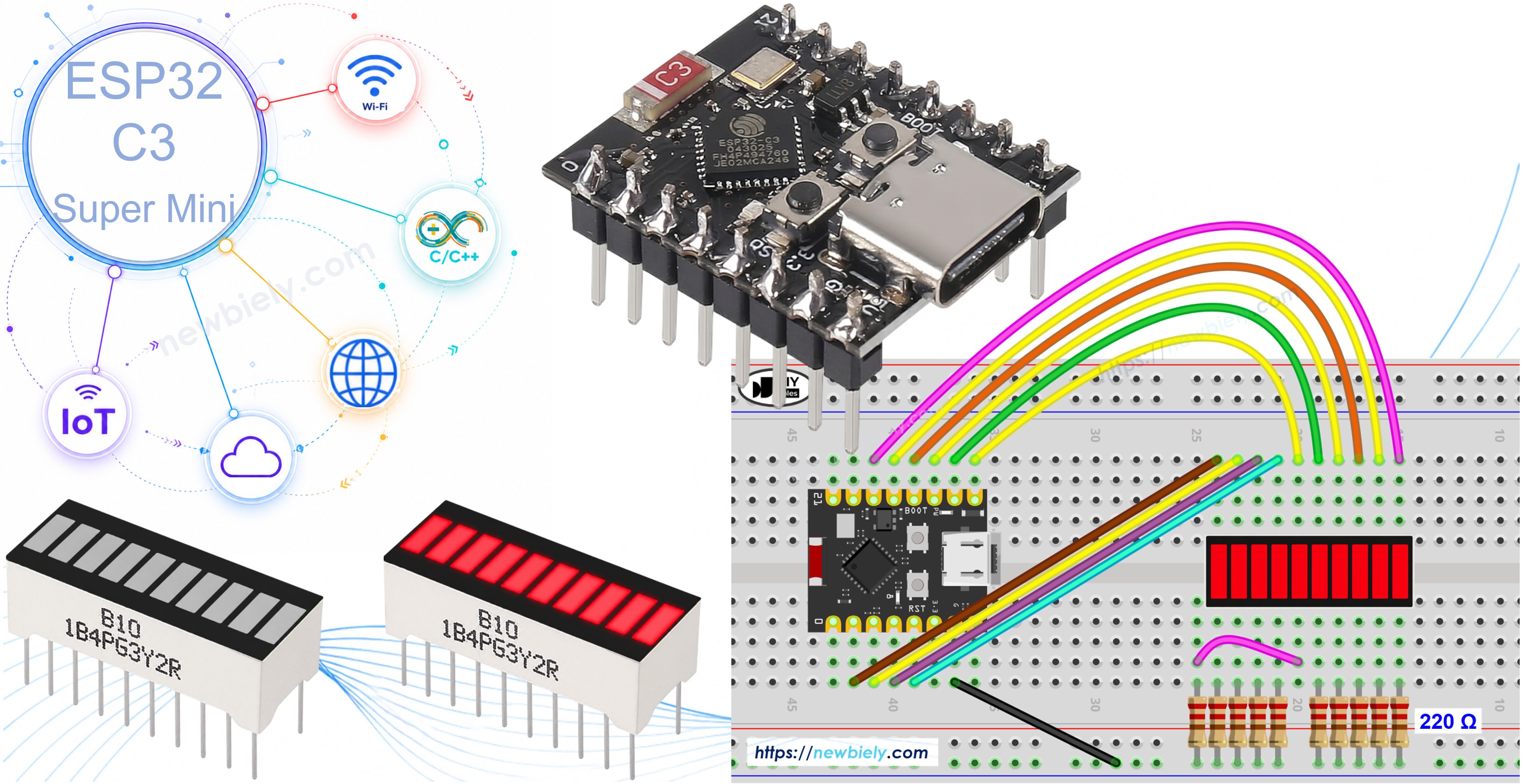
Overview of 10 Segment LED Bar Graph
Key specifications:
- Number of Segments: 10
- LED Color: Bright red
- Forward Voltage: ~2V per segment
- Forward Current: 20mA max per segment
- Resistor Required: 220Ω per segment
- Library Required: None — uses built-in digitalWrite()
Why use the LED Bar Graph:
- Simple and visual — perfect for showing levels at a glance
- No library needed — works with standard GPIO functions
- Compatible with ESP32 C3 Super Mini 3.3V logic
- Available as a ready-to-use component
LED Bar Graph Pinout
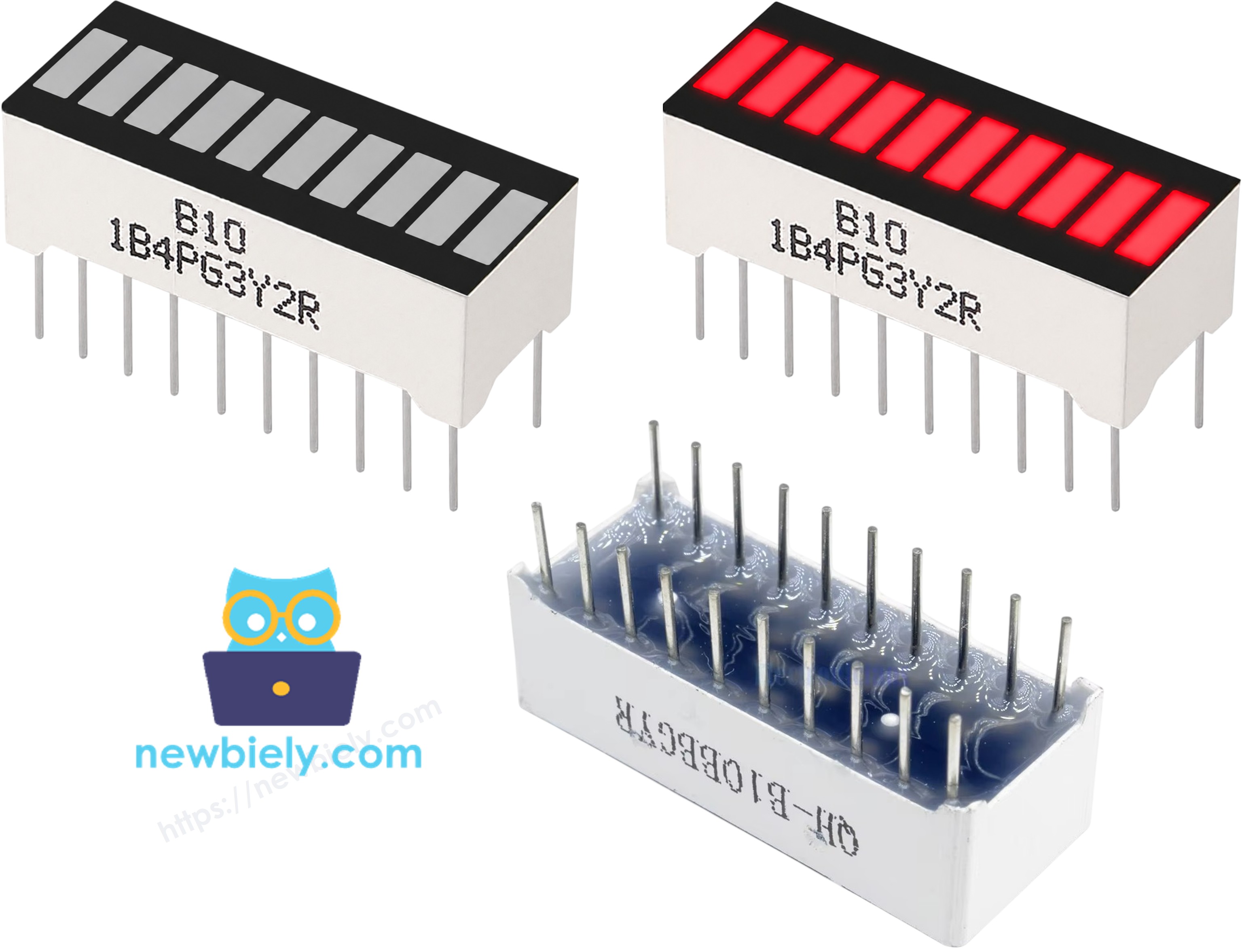
- A1–A10 (Anodes) — One anode per LED segment; connect each via 220Ω resistor to a GPIO pin
- K1–K10 (Cathodes) — One cathode per LED segment; connect all to GND
Wiring Diagram between 10 Segment LED Bar Graph and ESP32 C3 Super Mini
Here's how to connect the LED Bar Graph to the ESP32 C3 Super Mini:
| LED Bar Graph | ESP32 C3 Super Mini Pin |
|---|---|
| A1 (Anode 1) | GPIO1 (via 220Ω) |
| A2 (Anode 2) | GPIO2 (via 220Ω) |
| A3 (Anode 3) | GPIO3 (via 220Ω) |
| A4 (Anode 4) | GPIO4 (via 220Ω) |
| A5 (Anode 5) | GPIO5 (via 220Ω) |
| A6 (Anode 6) | GPIO6 (via 220Ω) |
| A7 (Anode 7) | GPIO7 (via 220Ω) |
| A8 (Anode 8) | GPIO8 (via 220Ω) |
| A9 (Anode 9) | GPIO9 (via 220Ω) |
| A10 (Anode 10) | GPIO10 (via 220Ω) |
| K1–K10 (Cathodes) | GND |
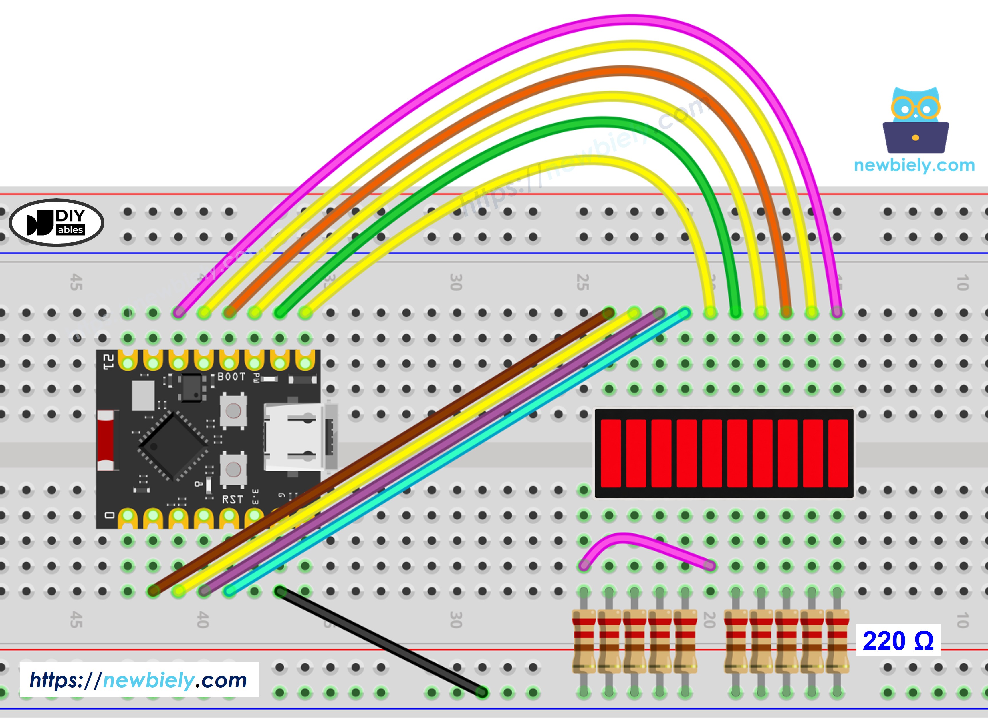
This image is created using Fritzing. Click to enlarge image
ESP32 C3 Super Mini Code - 10 Segment LED Bar Graph
Here's the code to animate the 10 Segment LED Bar Graph:
What this code does:
- Initializes GPIO 1–10 as outputs
- Lights up segments one by one from left to right (100ms per step)
- Waits 500ms when the bar is full
- Turns off segments one by one from right to left (100ms per step)
- Prints the current bar state to Serial Monitor
- Repeats in an infinite loop
/*
* This ESP32 C3 Super Mini code was developed by newbiely.com
*
* This ESP32 C3 Super Mini code is made available for public use without any restriction
*
* For comprehensive instructions and wiring diagrams, please visit:
* https://newbiely.com/tutorials/esp32-c3/esp32-c3-super-mini-10-segment-led-bar-graph
*/
const int NUM_SEGMENTS = 10;
const int ledPins[NUM_SEGMENTS] = {1, 2, 3, 4, 5, 6, 7, 8, 9, 10};
void printBar(int litCount) {
Serial.print("Bar: [");
for (int i = 0; i < NUM_SEGMENTS; i++) {
Serial.print(i < litCount ? "*" : " ");
}
Serial.println("]");
}
void setup() {
Serial.begin(115200);
for (int i = 0; i < NUM_SEGMENTS; i++) {
pinMode(ledPins[i], OUTPUT);
digitalWrite(ledPins[i], LOW);
}
}
void loop() {
for (int i = 0; i < NUM_SEGMENTS; i++) {
digitalWrite(ledPins[i], HIGH);
printBar(i + 1);
delay(100);
}
delay(500);
for (int i = NUM_SEGMENTS - 1; i >= 0; i--) {
digitalWrite(ledPins[i], LOW);
printBar(i);
delay(100);
}
delay(500);
}
- New to ESP32 C3 Mini? Complete our Getting Started with ESP32 C3 Mini tutorial first.
- Wire the components as shown in the diagram.
- Plug the ESP32 C3 Super Mini into your computer via USB Type-C.
- Open Arduino IDE and select ESP32 C3 Super Mini board and COM port.
- Copy the code above and paste it into Arduino IDE.
- Click Upload to compile and upload to the board.
- Watch the LED bar animate on your breadboard.
- Open Serial Monitor at 115200 baud to see the bar state printed.
Serial Monitor Output
8
Serial.println("Hello World!");
Message (Enter to send message to 'ESP32C3 Dev Module' on 'COM15')
New Line
9600 baud
Bar: [* ]
Bar: [** ]
Bar: [*** ]
Bar: [**** ]
Bar: [***** ]
Bar: [****** ]
Bar: [******* ]
Bar: [******** ]
Bar: [********* ]
Bar: [**********]
Bar: [********* ]
Bar: [******** ]
Bar: [******* ]
Bar: [****** ]
Bar: [***** ]
Bar: [**** ]
Bar: [*** ]
Bar: [** ]
Bar: [* ]
Bar: [ ]
Additional Knowledge
- Direct GPIO control (this tutorial): Uses 10 GPIO pins, simple code, no extra hardware
- Shift register (74HC595): Uses only 3 GPIO pins, requires additional IC and more complex code but saves GPIO pins