
Arduino Giga R1 WiFi NTC Thermistor Temperature Sensor
In this guide, we will learn how to read the temperature of a liquid, a surface or the air with the Arduino Giga R1 WiFi and a 10K NTC thermistor sealed in a steel probe. The probe is not a smart sensor. It holds one single part, the thermistor, and the Giga works out the temperature by itself through one analog pin. In detail, we will learn:
- The parts of the probe, and the job of the small 10K resistor packed with it.
- How to connect probe and resistor to the 3.3V, A0 and GND pins of the Giga R1 WiFi, and why the 5V pin is off limits here.
- Why the sketch reads A0 at 12 bits and takes the mean of ten samples.
- How the code goes from ADC counts to ohms to °C and °F, and what it prints when the probe is loose or shorted.
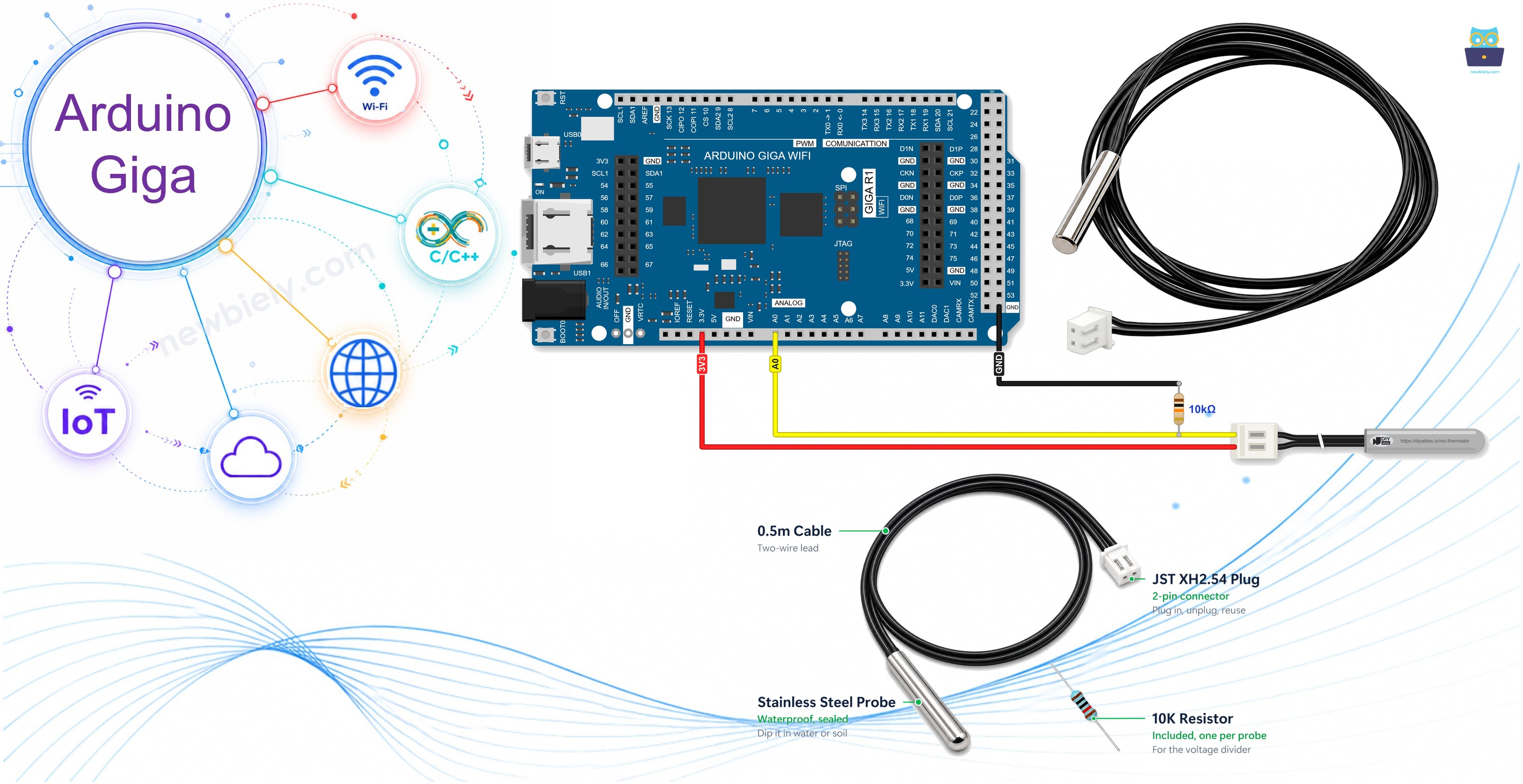
A Giga project often does many things at once: a screen, WiFi, a few motors. A thermistor probe adds a real thermometer to it for very little money and only one analog pin. Tape it to a battery pack, lower it into a hydroponic tank, clip it to a water heater pipe, or bury the tip in the soil of a greenhouse bed, and the Giga knows how warm it is there.
Hardware Preparation
Or you can buy the following kits:
| 1 | × | DIYables Sensor Kit (18 sensors/displays) |
Additionally, some of these links are for products from our own brand, DIYables .
Overview of NTC Thermistor Temperature Sensor
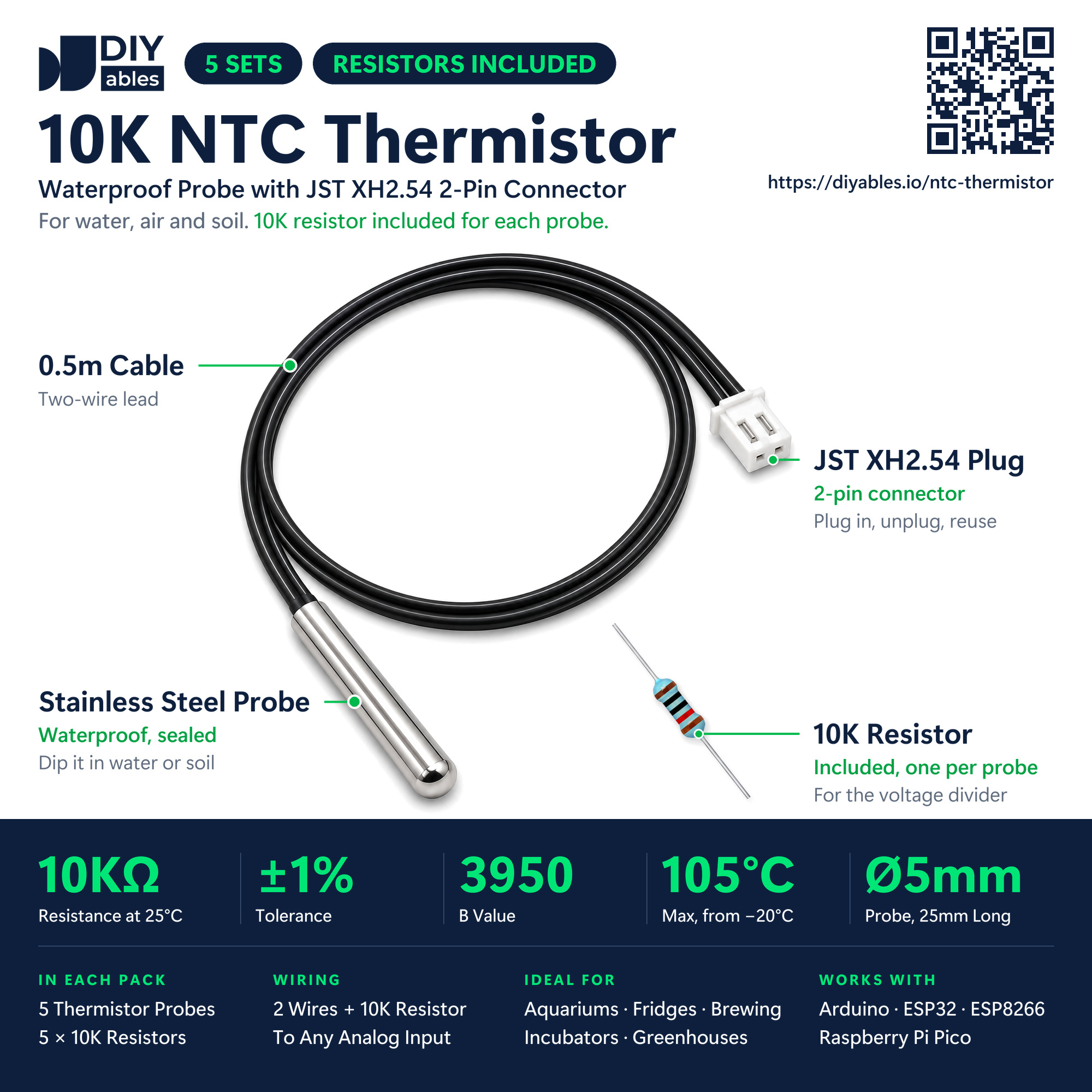
Three parts make up the probe. First the sensing end: a closed stainless-steel tube of 5mm x 25mm with a rounded tip, and the thermistor sealed inside it. Then the lead: a black cable, half a meter long, holding two wires. Last the connector: a white JST XH2.54 housing with two openings. Each opening takes the metal tip of a male jumper wire, so the probe connects to the Giga without any adapter board.
The DIYables kit packs five probes, and each one has a matching 10K resistor next to it. Do not lose these resistors: the Giga reads the probe through one of them, as the wiring part shows.
| NTC Probe Kit (DIYables) | |
|---|---|
| Sensing part | NTC thermistor, 10kΩ (25°C), tolerance ±1% |
| Beta constant | 3950 |
| Working range | from -20 to 105°C |
| Housing | sealed stainless-steel tube, 5mm wide, 25mm long |
| Lead | black, 2 cores, 50cm |
| Plug | JST XH2.54 (white), 2-way |
| Insulation | over 100MΩ |
| In the kit | 5 probes, 5 resistors of 10K |
The two wires are equal. Turn the connector around and the reading stays the same, because current passes through a thermistor in both directions alike. With the jumper wires pushed into the connector:
- First probe wire: to 3.3V on the Giga.
- Second probe wire: to A0, the same point where the 10K resistor starts.
- Other end of the 10K resistor: to GND on the Giga.
Heat makes this thermistor conduct better. That is what the letters NTC (Negative Temperature Coefficient) tell you: temperature up, resistance down; temperature down, resistance up. The ADC of the Giga reads volts, though, not ohms, so the 10K resistor is added below the probe. Together they divide the 3.3V, and A0 is connected to their meeting point. As the probe warms up and its resistance drops, that point moves closer to 3.3V. As it cools down, it sinks toward GND. From the voltage, the code calculates the probe resistance, and from the resistance, the degrees.
What the Giga sees at a few temperatures (3.3V on top, 12-bit reading):
| Probe at | Its resistance | Voltage at the joint | analogRead() (0-4095) |
|---|---|---|---|
| -12°C | about 65.3kΩ | 0.44V | 544 |
| 3°C | about 28.7kΩ | 0.85V | 1057 |
| 14°C | about 16.6kΩ | 1.24V | 1539 |
| 27°C | about 9.2kΩ | 1.72V | 2138 |
| 55°C | about 2.98kΩ | 2.54V | 3155 |
The table also shows that the curve is far from straight. The 11 degrees from 3°C to 14°C take away about 12kΩ, while the 28 degrees from 27°C to 55°C take away only about 6kΩ. A straight-line scale would be wrong at both ends, so the code uses the beta formula of the thermistor:
1/T = 1/T0 + (1/B) × ln(R/R0)
Put in R, the resistance the Giga has measured, and the three fixed values of this probe: R0 = 10000Ω, T0 = 298.15K (25°C plus 273.15) and B = 3950. You get T in kelvin; minus 273.15 makes it degrees Celsius. Some projects use the Steinhart-Hart formula instead. It has three coefficients and comes a bit closer to the truth over a wide range, but the beta formula is fine for this probe. Expect an error of roughly 1°C around room temperature, plus whatever the 10K resistor and the Giga ADC add.
Wiring Diagram
Three Giga pins are used. 3.3V feeds the top of the probe, GND takes the bottom of the 10K resistor, and A0 reads the middle point between them.
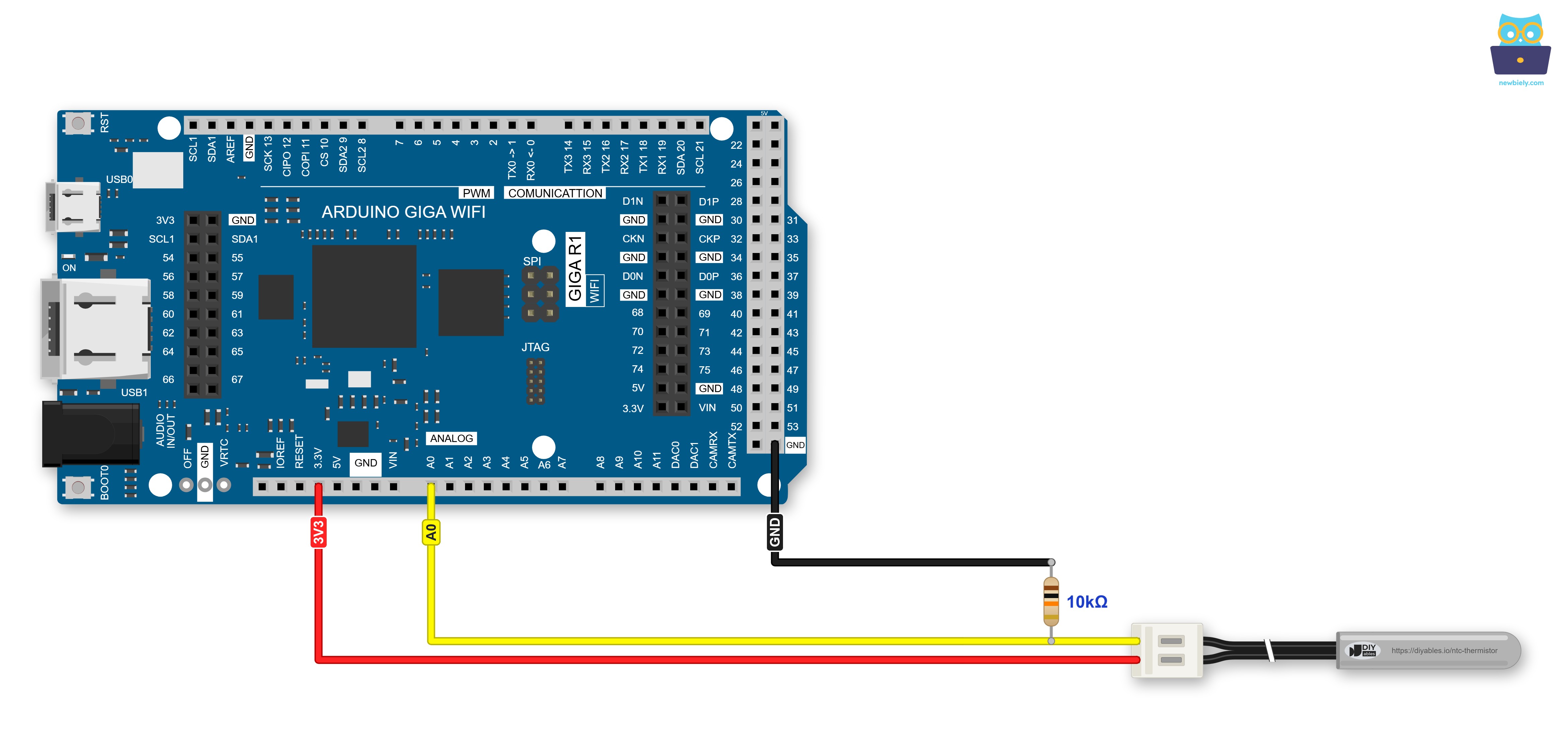
This image is created using Fritzing. Click to enlarge image
| Thermistor Divider | Arduino Giga R1 WiFi Pin |
|---|---|
| Thermistor lead, any | 3.3V |
| Thermistor lead, other | A0 |
| Fixed 10K, upper lead | A0 |
| Fixed 10K, lower lead | GND |
The diagram shows no breadboard: the resistor is simply drawn from the A0 wire to the GND wire. In real life, build that joint on a small breadboard. One row holds the probe wire, the A0 jumper and the upper resistor lead; a second row joins the lower resistor lead with the GND jumper. Without a breadboard, wind the resistor leads tightly around the metal pins of the jumper wires (or solder them there), and put a strip of insulating tape over each joint so it cannot touch anything.
※ NOTE THAT:
- Keep the probe on 3.3V. Do not move it to 5V or VIN. Every analog input of the Giga is made for 3.3V at most, and the voltage on A0 rises as the probe heats up. With 5V feeding the divider, a hot probe could push A0 past the safe limit.
- There is a second reason for 3.3V. The Giga ADC compares each input with a 3.3V reference from the same supply of the board. When the divider hangs on that supply too, a reading of about 2048 always means "probe and resistor are equal, 10kΩ each", whatever the real supply voltage is. So the code works with the ratio raw / 4095, and a slightly high or low supply does not matter.
A0 is only our choice. If it is busy in your project, use another analog pin of the Giga and change THERMISTOR_PIN in the code.
How To Program For NTC Thermistor
Everything here is built in: analogRead() comes with the Giga core, and log() with the standard C math library.
- In setup(), switch analogRead() to 12-bit results (0 to 4095). By default, the Giga returns 10-bit values (0 to 1023). The extra bits make the steps smaller; the accuracy of the probe stays the same.
- Take ten samples, 10 ms apart, and use their mean. In the sketch, this is the helper readAverageRaw(), which keeps the small jumps of single readings out of the result.
- Compute the probe resistance from that mean:
- Get degrees from ohms. Careful: in C and C++, log() gives the natural logarithm, which is "ln" in the formula above, and not log10():
- Add the Fahrenheit value:
- Before any of this math, look at the mean. Under 20, the probe is missing; over 4075, something is shorted. For these two cases, the sketch skips the formula and tells you what to check, because the math would only give "inf" or "nan".
Arduino Giga R1 WiFi Code - NTC Thermistor Temperature Sensor
Here are all the steps in one sketch. Every second it prints the temperature first, in °C and °F. Behind it, in brackets, come the probe resistance and the averaged A0 value. You do not need them for the temperature, but they help a lot when something looks wrong.
Detailed Instructions
Follow these instructions step by step:
- New to the Giga? Install its board package first with the Arduino Giga R1 WiFi getting started guide.
- Wire the components according to the provided diagram: the thermistor from 3.3V to A0, the 10K resistor from A0 down to GND.
- Connect the Giga R1 WiFi to your computer through the USB Type-C cable.
- Launch the Arduino IDE on your computer.
- Select the appropriate Arduino Giga R1 WiFi board (e.g., Arduino Giga R1 WiFi) and COM port.
- Put the sketch into an empty IDE tab and press Upload.
- Open the Serial Monitor (9600 baud) and let three lines pass with the tip in the room air.
- Prepare two cups: one with water from the cold tap, one with warm water (about as warm as a bath). Dip the tip into the cold cup, wait a few seconds, then move it to the warm cup.
Lines 1 to 3: room air, close to 23.6°C. Lines 4 to 7: the cold cup. The resistance grows to about 16.5kΩ, and the value settles near 14°C, a normal temperature for tap water. Lines 8 to 11: the warm cup. The resistance falls to about 5kΩ, and the value climbs to 41°C. Notice how few lines each change needs. Water carries heat to the steel tube much faster than air does, so in a liquid the probe follows within a few seconds. In still air, give it longer.
A simple test of accuracy: crushed ice plus a little cold water, stirred well, stays at 0°C. Put the tip in it for a minute. The Giga should then show a value within about one degree of zero.
When a warning line shows up in place of the temperature:
- "A0 reads almost 0": nothing lifts A0. Check that both jumper pins sit firmly in the white connector and that the first probe wire really lands on 3.3V.
- "A0 reads almost 3.3V": A0 is pulled up too hard. Usually the 10K resistor has fallen out of the breadboard, or the bare A0 and 3.3V wires are touching each other.
Planning a build that runs for weeks? Water may reach only the steel tube: the white connector and the bare resistor leads need to stay dry. And never let the tip go above 105°C. For hotter jobs, like a kiln or a soldering station, choose a thermocouple sensor.
If you prefer a sensor that does the math inside and sends a ready number over one data wire, the waterproof DS18B20 probe is covered in the Arduino Giga R1 WiFi - Temperature Sensor tutorial.