
Arduino Giga R1 WiFi Slide Switch
In this guide, we will learn how to use the DIYables Mini Slide Switch SS12D10 with the Arduino Giga R1 WiFi. The Giga often runs big projects: a WiFi display, a robot arm, or a data logger with many sensors. Such a project often needs one setting that must stay the same until you change it by hand. A "maintenance mode" that keeps a motor stopped while you work on the machine is one example. A night setting that turns a screen dark is another. A slide switch gives the Giga this kind of setting for very little money. In detail, we will learn:
- How the handle of the SS12D10 joins its middle pin (COM) to one of the two outer pins.
- How to connect the switch to D7, GND and 3.3V of the Giga, and why the 5V pin stays unused.
- How to print the position once at start, and then one numbered line for each real move, with a 50 ms debounce.
- How to save one wire with INPUT_PULLUP, and why ON and OFF then swap places.
Please do not confuse the slide switch with these parts, which have their own Giga tutorials:
- ON/OFF rocker switch: a larger panel switch that you flip with a finger.
- Button module: it springs back as soon as you let go.
- Limit switch: it is pressed by a moving part of a machine, not by your hand.
Hardware Preparation
Or you can buy the following kits:
| 1 | × | DIYables Sensor Kit (18 sensors/displays) |
Additionally, some of these links are for products from our own brand, DIYables .
Overview of Slide Switch
The SS12D10 is a small switch with a 5mm handle on top and three legs in one row underneath. Push the handle to one end and it stays there. Push it back and it stays at the other end. This is called a latching switch. A push button works the other way: it jumps back the moment you lift your finger. So a button is good for "do something now", and a slide switch is good for "keep this setting".
In part lists, you will see it called SPDT (single pole, double throw) or 1P2T. Both names mean the same thing: one common pin that can connect to one of two sides.
| Mini Slide Switch SS12D10 | |
|---|---|
| Contact type | SPDT (1P2T), 2 positions |
| Pins | 3 through-hole pins, 4.7mm pitch |
| Pin length | 6.9mm |
| Handle length | 5mm |
| Body size | about 12.8 x 6.7 x 18.2mm |
| Mounting | vertical, through-hole |
| Contact material | silver-plated brass |
| Contact rating | AC 125V 2A |
| Switching life | more than 100,000 cycles |
| Operating temperature | -25°C to 80°C |
The AC 125V 2A value is the most the contacts can carry. In this guide, the switch only carries a tiny signal current into one input pin of the Giga, which is far below that limit.
When the handle moves, the metal contacts bounce for a few milliseconds before they settle. The Giga is fast enough to see each bounce as a separate change. Our code waits 50 ms and checks again, so one move gives one line on the screen.
Pinout
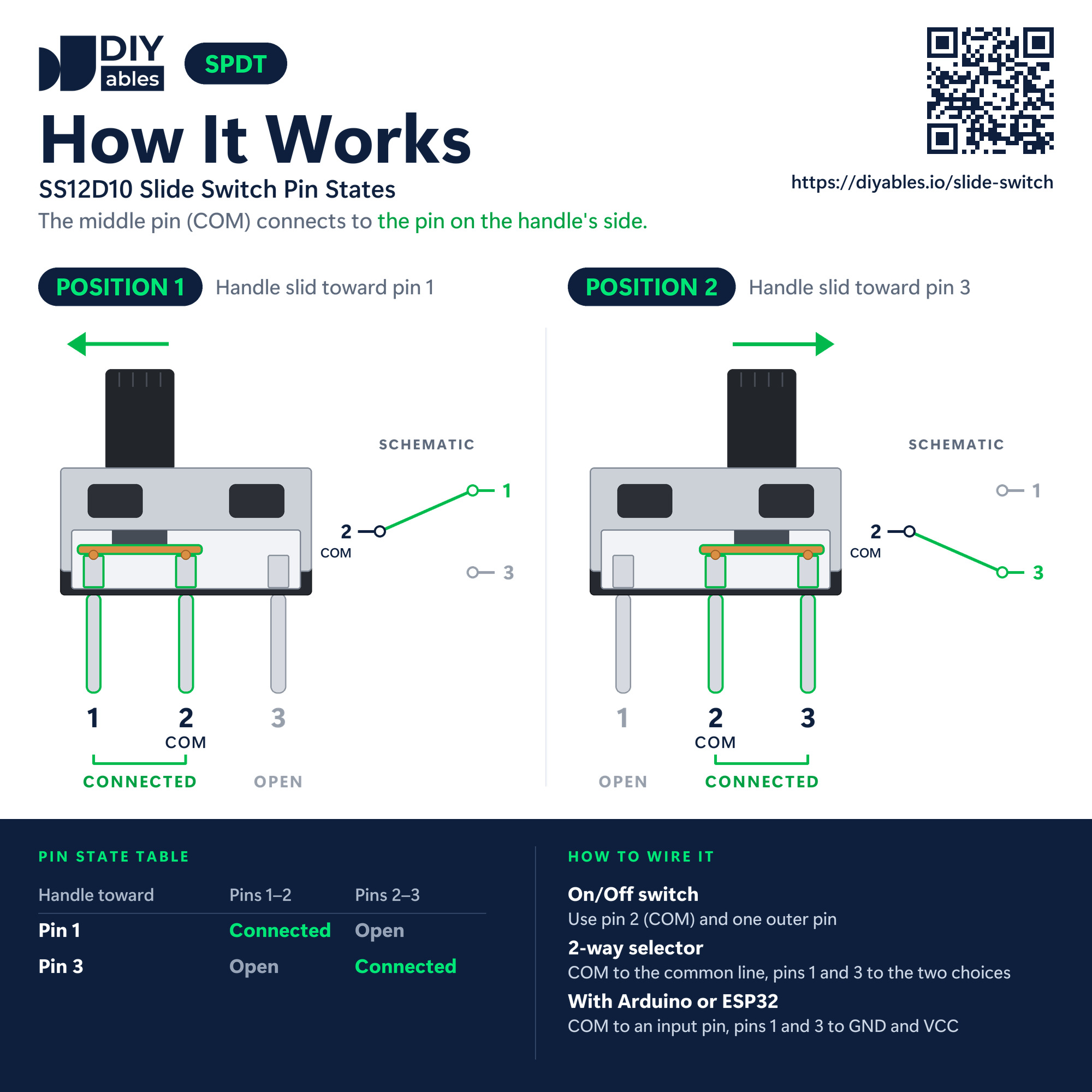
The SS12D10 has no pin labels. Hold it with the legs pointing down: the leg in the center is always COM.
- Pin 1 (outer pin): connect to a GND pin of the Giga (0V).
- Pin 2, COM (middle pin): connect to digital pin 7 (D7) of the Giga. It carries the voltage of the outer pin that the handle has picked.
- Pin 3 (outer pin at the other end): connect to the 3.3V pin of the Giga.
A thin metal bridge moves with the handle. One end of it always touches COM. The other end touches the outer pin on the handle's side:
- Handle toward pin 1: pins 1 and 2 are connected, pin 3 is open. D7 sees GND and reads LOW. We call this OFF.
- Handle toward pin 3: pins 2 and 3 are connected, pin 1 is open. D7 sees 3.3V and reads HIGH. We call this ON.
Wiring Diagram
Three jumper wires go from the switch to the Giga, with no breadboard. COM is always tied to GND or to 3.3V through the switch, so there's no need to add a pull-up or pull-down resistor. This makes wiring or soldering easier.
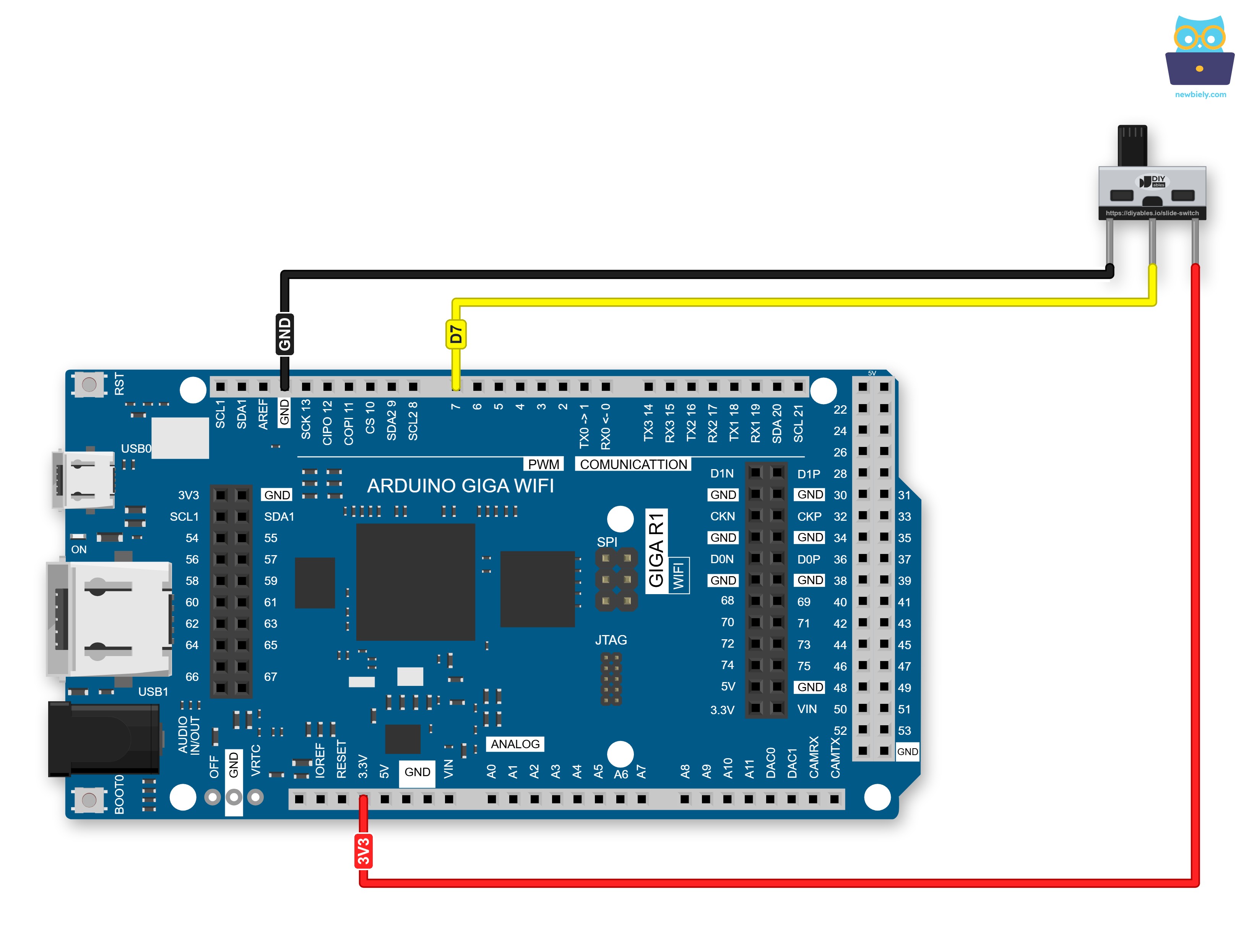
This image is created using Fritzing. Click to enlarge image
| Slide Switch Pin | Arduino Giga R1 WiFi Pin |
|---|---|
| Pin 1 | GND |
| Pin 2 (COM) | D7 |
| Pin 3 | 3.3V |
※ NOTE THAT:
- Pin 3 of the switch goes to the 3.3V pin, never to 5V or VIN. In the ON position, COM passes the voltage of pin 3 straight to D7, and the GPIO pins of the Giga work at 3.3V only. A 5V level can damage the pin.
- Keep D7 as an input. Never make it an OUTPUT: the switch ties it directly to 3.3V or GND, so an output pin would be shorted.
D7 is only our choice. The Giga has dozens of digital pins, so if D7 is busy in your project, pick another one and change SLIDE_SWITCH_PIN in the code. For a project that stays built for a long time, solder the wires to the switch legs, so they cannot slip off.
How To Program For Slide Switch
No library is needed. You read a slide switch with digitalRead(), just like a button.
- Choose the Giga pin that is wired to COM:
- Set it as a normal input in setup(). Pin 1 and pin 3 already give LOW and HIGH, so the internal pull-up is not needed:
- Read where the handle is. HIGH means toward pin 3 (ON), LOW means toward pin 1 (OFF):
- Filter the bounce: when a reading is different from the saved one, wait 50 ms, read again, and keep the new value only if it is still different.
Arduino Giga R1 WiFi Code - Slide Switch
The sketch prints the handle position once, right after it starts. Then it watches D7 and prints a numbered line each time the handle really moves. The number helps you check that one move gives exactly one line.
Detailed Instructions
Follow these instructions step by step:
- Is this your first sketch on the Giga? Install its board package with the Arduino Giga R1 WiFi getting started guide first.
- Wire the components according to the provided diagram: pin 1 to GND, COM to D7, pin 3 to 3.3V.
- Connect the Giga R1 WiFi to a USB port of your computer with the USB Type-C cable.
- Launch the Arduino IDE on your computer.
- Select the appropriate Arduino Giga R1 WiFi board (e.g., Arduino Giga R1 WiFi) and COM port.
- Copy the code above into a new sketch and click Upload.
- Open the Serial Monitor and set the speed to 9600 baud.
- Slide the handle from end to end six times and watch the lines appear.
Six moves give six "change" lines, and the counter never jumps by two, so the bounce is filtered. If you leave the handle alone, the screen stays quiet. The sketch prints only when something changes.
The "[startup]" line comes only once, at the very start of the sketch. The Giga talks to your computer through its own USB port, and that port reconnects after each upload. If the Serial Monitor was not ready yet, this first line is lost. That is not a problem: the next "change" line tells you where the handle is. If you see ON while the handle points to pin 1, check that pin 1 goes to GND and pin 3 to 3.3V, not the other way round.
Arduino Giga R1 WiFi Code - Slide Switch on Two Wires (INPUT_PULLUP)
Want fewer wires, or does a sensor already use the 3.3V pin? Then let the Giga do the job of pin 3 by itself. Every GPIO pin of the STM32H747 chip has a pull-up resistor inside, and INPUT_PULLUP turns it on. Just remove the pin 3 wire. COM stays on D7, pin 1 stays on GND, and pin 3 is left free.
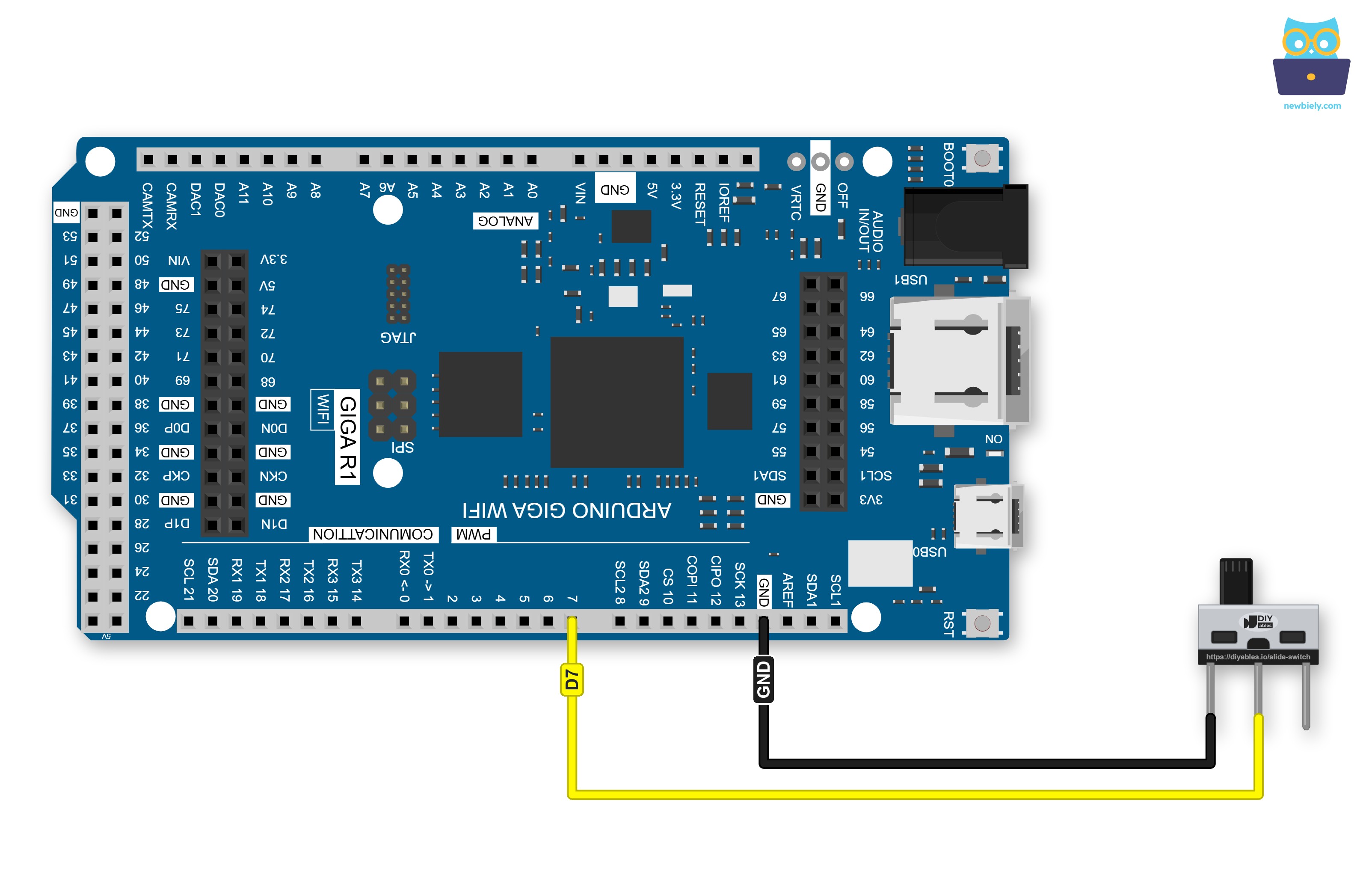
This image is created using Fritzing. Click to enlarge image
| Slide Switch Pin | Arduino Giga R1 WiFi Pin |
|---|---|
| Pin 1 | GND |
| Pin 2 (COM) | D7 |
| Pin 3 | not connected |
Be careful: HIGH and LOW now mean the opposite of before.
- Handle toward pin 1: COM is joined to GND, so D7 reads LOW. The sketch prints ON.
- Handle toward pin 3: COM touches a free pin, so nothing drives D7. The internal pull-up holds it HIGH, and the sketch prints OFF.
Detailed Instructions
- Unplug the wire between pin 3 of the switch and the 3.3V pin. Leave the handle toward pin 1.
- Upload this sketch in the same way as the first one.
- Keep the Serial Monitor at 9600 baud, then slide the handle three times: toward pin 3, back toward pin 1, and toward pin 3 again.
Compare these lines with the first test. With the handle toward pin 1, the 3-wire sketch printed OFF, but this sketch prints ON. With the handle toward pin 3, it is the other way round. Both are right, because the wiring is different.
Which version should you use? The 3-wire one reads the natural way, with HIGH as ON. The 2-wire one needs fewer wires, and it keeps the 3.3V pin free for other parts of a big Giga project.