
Arduino Giga R1 WiFi BTS7960 Motor Driver
In this guide, we will learn how to use the BTS7960 motor driver with the Arduino Giga R1 WiFi to turn a strong 12V DC motor both ways, with soft speed changes. Our example is a motorized camera slider: a carriage holds the camera and travels along a rail, so the video shot moves slowly and evenly across the scene. In detail, we will learn:
- The chips, header pins and screw terminals of the BTS7960 module, one by one.
- A simple table that turns RPWM, LPWM, R_EN and L_EN into motor moves: forward, reverse, brake and coast.
- How the Giga, the module, the motor and the 12V adapter are wired, and why VCC takes 5V here while the signals stay at 3.3V.
- How to write a program for the Giga that eases the motor in and out, brakes it, sends it back and lets it go.
Why such a big driver for a camera slider? A long rail with a heavy camera, a large lens and a belt needs a 12V gear motor with real force, and that motor pulls a lot of current when it starts. The BTS7960 has plenty of current to spare for that. The second point is smoothness. A sudden start shakes the camera, and the shake shows up in the video. So the code in this guide never jumps to full speed. It raises and lowers the PWM duty one small step at a time.
Hardware Preparation
Or you can buy the following kits:
| 1 | × | DIYables Sensor Kit (18 sensors/displays) |
Additionally, some of these links are for products from our own brand, DIYables .
You do not need the rail, the carriage or the belt for this guide. Test the motor on its own first, and fit it to the slider later.
Overview of BTS7960 Motor Driver
Turn the DIYables BTS7960 43A Motor Driver Module over, and the first thing you notice is a big heat sink fixed under the board. On the top side are the parts it cools: two Infineon BTS7960B chips. Next to them sit a small 74HC14 chip and the control header. One BTS7960B alone is a half-bridge; the two together form a full H-bridge. That is enough for one brushed DC motor, spinning either way, with PWM setting the speed. "IBT-2" and "HW-039" are two other names you will see for this exact board. It picks up where an L298N or a DRV8833 has to give up: wheelchair motors, winches, car wipers, electric scooters, large gear motors and heavy robots.
| BTS7960 Motor Driver Module | |
|---|---|
| Driver chips | two Infineon BTS7960B half-bridges = one H-bridge |
| Motors | a single brushed DC motor, two directions |
| Motor voltage (B+ / B-) | 5.5 to 27V DC (suits 6V, 12V and 24V motors) |
| Current | 43A max, the current-limit (peak) level of the chip |
| Highest PWM frequency | 25 kHz (RPWM, LPWM) |
| Logic buffer | 74HC14, runs from VCC |
| Protection | current limiting and over-temperature protection |
| Sense outputs | R_IS, L_IS (current sense / error signal) |
About the big number: 43A is a peak, the point where the current limit of the chip steps in. A slider can run for a long time, one slow take after another, so plan for a motor current far below it. The size of the heat sink sets the long-term limit of the board.
How the H-bridge works, in short: every motor wire has its own chip, and that chip can link the wire to B+ or to B-. Put the right-hand wire on B+ and the left-hand wire on B-, and current crosses the motor in one direction. Reverse the pattern, and the current and the shaft reverse too. For speed, PWM flicks the supply on and off very quickly. More on-time (a higher duty cycle) means more speed. The Giga never talks to the power chips directly. Its signals first pass the 74HC14 buffer chip (on the product page it goes by "isolation chip"). That little chip and the power LED are the only things the VCC pin feeds. Motor power never comes from VCC.
Pinout
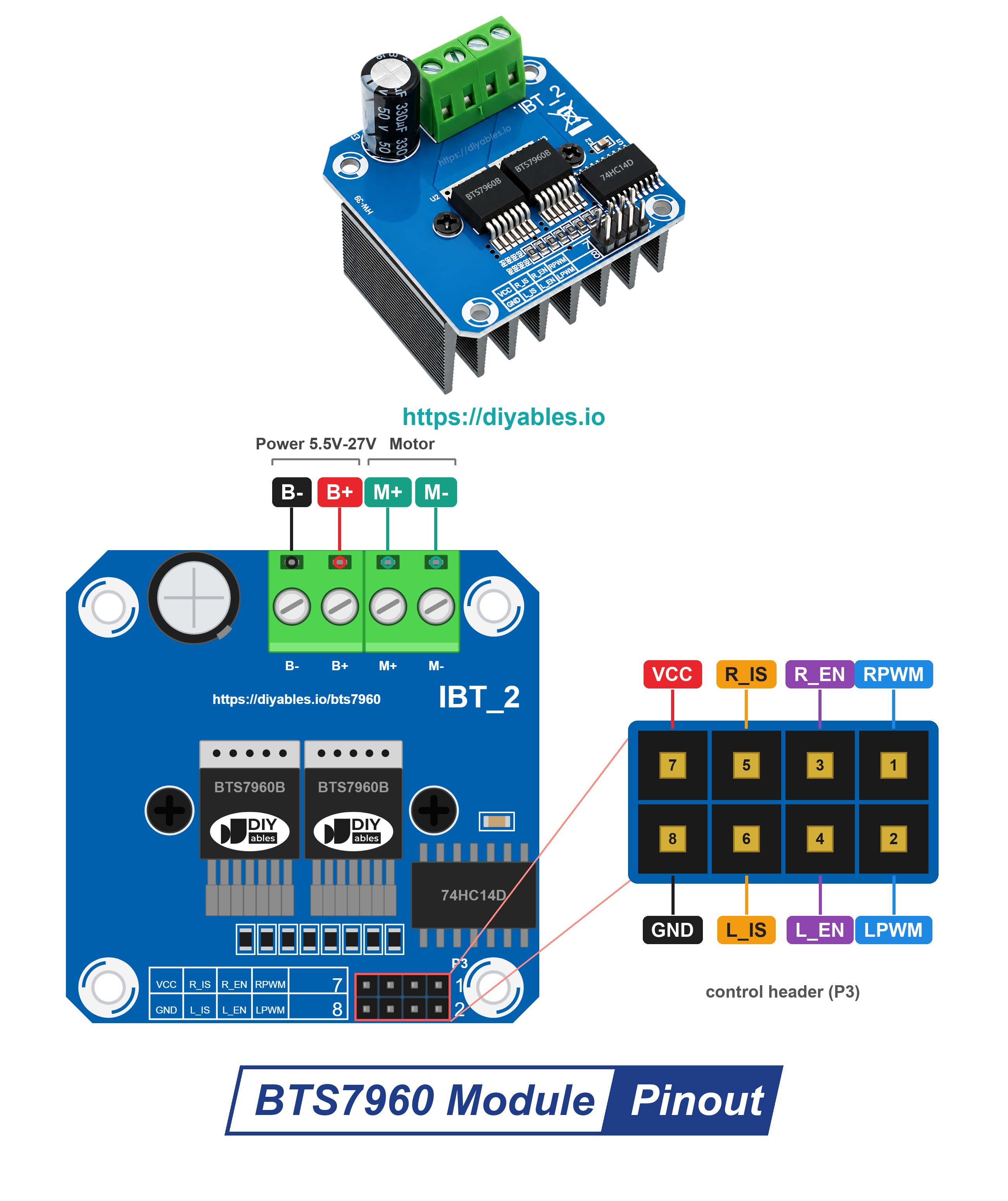
Count four pins in each of the two header rows. Upper row: VCC, R_IS, R_EN, RPWM. Lower row: GND, L_IS, L_EN, LPWM. Do not look for "R_IS" and "L_IS" in print: the board labels them "R_S" and "L_S".
On the 8-pin header:
- RPWM pin: give it PWM, and the right half-bridge pushes the motor forward. Connect to D9 of the Giga.
- LPWM pin: give it PWM, and the left half-bridge pushes the motor in reverse. Connect to D10.
- R_EN pin: master switch of the right half-bridge. HIGH lets it work, LOW shuts it off. Connect to D12.
- L_EN pin: master switch of the left half-bridge. HIGH lets it work, LOW shuts it off. Connect to D11.
- R_IS and L_IS pins: current-sense and error outputs. A slider has no use for them, so leave them empty.
- VCC pin: logic supply for the 74HC14 chip only. Connect to the 5V pin of the Giga.
- GND pin: connect to a GND pin of the Giga. It is wired to B- on the module.
On the screw terminal block (the high-current side):
- B+ terminal: connect to the + of the 12V adapter.
- B- terminal: connect to the adapter's - (minus).
- M+ and M- terminals: one motor wire on each.
Forward, Reverse, Brake and Coast
While R_EN and L_EN are HIGH, the two PWM pins choose the move:
| RPWM | LPWM | Motor action |
|---|---|---|
| duty 0-255 | 0 | forward; speed follows the duty cycle |
| 0 | duty 0-255 | reverse; speed follows the duty cycle |
| 0 | 0 | brake; motor wires joined inside the driver, fast stop |
Coast is the fourth state, and it needs the enable pins: set R_EN and L_EN LOW. Then neither half-bridge drives the motor, and it spins down on its own.
On a slider, you can see the difference. With brake, the carriage stops almost where the shot should end. With coast, it rolls on for a short distance.
Take care when you write your own code: if RPWM gets PWM, LPWM must be 0, and the other way round. PWM on both pins at once is never allowed.
Power, Ground and 3.3V Logic
- All motor current flows in from the 12V adapter, by way of the DC power jack. Its + screw goes to B+, its - screw to B-. The current rating of the adapter should be higher than what your motor draws.
- Keep the 12V of B+ away from the Giga. No Giga pin may ever touch it.
- Common ground comes for free: the module links its GND pin to B- on the board. The single GND jumper from the Giga is all you need, with no extra wire to B-.
- Use the 5V pin of the Giga for VCC. The only load on VCC is the small 74HC14 buffer chip, and the guide of the module lists 5V for it. 3.3V signals are inside the input range of the control pins, so the Giga R1 WiFi pins can be wired straight to them.
- Data flows in a single direction, from the Giga to the module. The four control inputs only have pull-down resistors, and nothing is wired to R_IS and L_IS, so the module has no path to push 5V into the Giga.
- Swapped + and - can damage the module. Look at the adapter polarity twice before the plug goes in.
Wiring Diagram
Think of the build as a low-power part and a high-power part. The low-power part is the Giga, powered by USB, talking to the control header over six jumper wires (RPWM, LPWM, R_EN, L_EN, 5V and GND). The high-power part: the 12V adapter plus the motor. They connect to the screw terminals of the module and nowhere else.
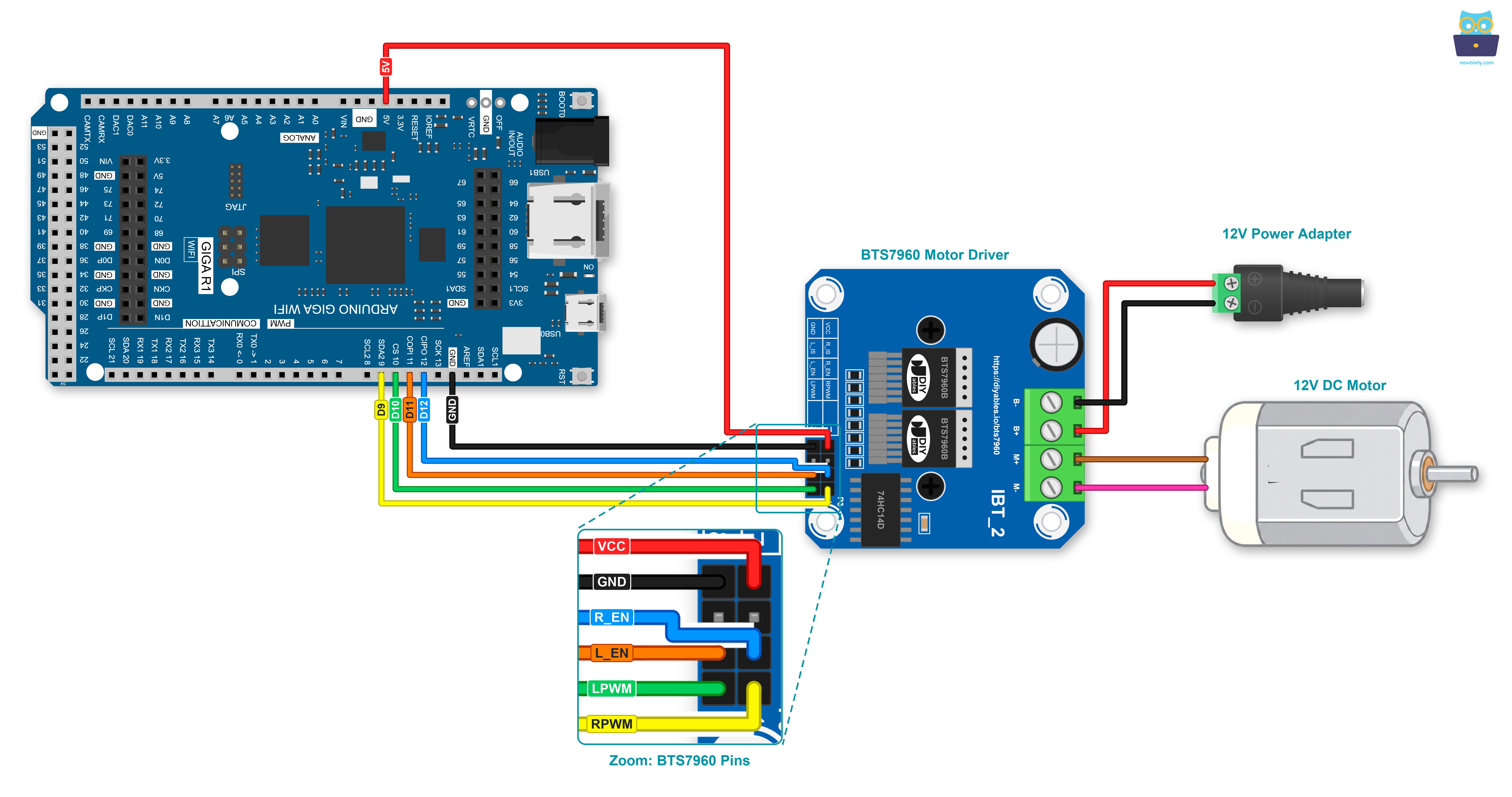
This image is created using Fritzing. Click to enlarge image
| BTS7960 Pin | Connect To |
|---|---|
| RPWM | Arduino Giga R1 WiFi D9 |
| LPWM | Arduino Giga R1 WiFi D10 |
| R_EN | Arduino Giga R1 WiFi D12 |
| L_EN | Arduino Giga R1 WiFi D11 |
| VCC | Arduino Giga R1 WiFi 5V |
| GND | Arduino Giga R1 WiFi GND |
| R_IS, L_IS | no wire |
| B+ | power jack, + terminal (12V) |
| B- | power jack, - terminal |
| M+, M- | the motor leads (either way round) |
Before you power anything, check these points:
- R_EN lands on D12 and L_EN on D11, which is easy to swap by mistake. The code always switches both enable pins together, so a swap would not change how the motor runs. Still, follow the table, so your wires match the comments in the code.
- RPWM and LPWM need PWM pins. On the Giga, D2 to D13 can all make PWM. If D9 or D10 is busy in your project, move the wire and change the pin number at the top of the code.
- Make every connection with the 12V adapter unplugged.
How To Program For BTS7960 Motor Driver
No library to add: the Giga board package brings analogWrite() (for the speed) and digitalWrite() (for the enable pins) with it.
- Store the pin numbers in constants:
- Prepare the pins in setup(). The PWM pins are set to 0 first, and the enable pins go HIGH after that, so the shaft stays still at the moment the driver turns on:
- Drive the carriage forward (duty 0 to 255), with LPWM cleared first:
- Drive it back, with RPWM cleared first:
- Stop hard: both PWM values at 0 while the enable pins stay HIGH:
- Let it roll: after the PWM pins are at 0, drop both enable pins LOW:
- Ease in for a smooth shot: raise the duty by 1 every few milliseconds, instead of jumping straight to 255:
Arduino Giga R1 WiFi Code - BTS7960 Motor Driver
Here is a camera slider test run in code form. It loops forever, and its helper functions carry slider names: slideForward(), slideBack(), brakeCarriage(), releaseMotor() and enableDriver(). One round goes like this:
- Glide out: the speed rises from 0 to full in about 2 seconds.
- The motor cruises at full speed for 2 seconds.
- The speed falls back to 0, again in about 2 seconds.
- Hold: the driver brakes for 1 second.
- Return: reverse at roughly half speed (duty 128) for 2 seconds.
- Release: the driver turns off and the motor coasts for 2 seconds. Then the driver turns on again.
Detailed Instructions
Follow these instructions step by step:
- Is this your first Giga project? Set up its board package with the Arduino Giga R1 WiFi getting started guide.
- Connect all parts as the wiring diagram shows. The 12V adapter stays unplugged at this point.
- Hold the motor down with a clamp or strong tape. If it is already on the slider, take the belt off for this first test, because the test code does not know where the rail ends.
- Link the Giga R1 WiFi to your computer over the USB Type-C cable.
- Start the Arduino IDE on your computer.
- Select the appropriate Arduino Giga R1 WiFi board (e.g., Arduino Giga R1 WiFi) and COM port.
- Paste the sketch into an empty IDE window, then press Upload. No library is needed.
- When the upload is done, connect the 12V adapter to the DC power jack.
- Choose 9600 baud in the Serial Monitor, then follow the motor shaft line by line.
What to look for:
- The shaft speeds up and slows down gently, with no jerk at the start or at the end. This is the movement you want on a slider.
- Compare the two stops: after "Hold", the shaft is still almost at once; after "Release", it spins on briefly with no power behind it.
- At "Return", the shaft turns the other way, at a lower speed.
Carriage heading the wrong way on "Glide out"? Pull the 12V plug, then swap the wire on M+ with the wire on M-. Leave the sketch as it is.
A soft whine at slow speeds is expected. The analogWrite() of the Giga pulses at roughly 500 Hz, which is well inside the range people hear. For video work, note that the camera microphone may catch this whine. The BTS7960 itself accepts PWM up to 25 kHz, so a faster PWM can make the motor quiet, but that is a topic for another day.
※ NOTE THAT:
Text in the Serial Monitor, but a silent motor? Start at the power side: the 12V plug must be in, with + on B+. Then look at the GND jumper. Last, check the enable jumpers on D12 and D11. The motor uses both half-bridges in every direction, so one loose enable wire stops it completely.
Ideas for the next step on your slider:
- Put a limit switch at each end of the rail, so the carriage stops by itself before it hits the end.
- Use the built-in WiFi of the Giga to start a take from your phone.
Only spinning a small motor? A BTS7960 is oversized for that job, and the Arduino Giga R1 WiFi - DRV8833 DC Motor Driver guide fits better. Against the popular L298N, the trade is simple: an L298N handles two motors of about 2A each but wastes about 2V inside, while the BTS7960 runs a single motor, but with far more current and almost no voltage drop.