Arduino MKR WiFi 1010 - 74HC595 4-Digit 7-Segment Display

This recipe walks you through using a 4-digit 7-segment display with 74HC595 shift register on the Arduino MKR WiFi 1010. The MKR WiFi 1010 combines a SAMD21 processor with an ESP32-based NINA-W102 module for Wi-Fi and BLE connectivity. It runs at 3.3V, includes a LiPo battery connector for portable projects, and exposes a clean set of I/O pins on its compact MKR header layout.

Ingredients in this recipe:

Arduino MKR WiFi 1010 74HC595 4-Digit 7-Segment Display

Hardware Preparation

1×Arduino MKR WiFi 1010
1×Micro USB Cable
1×74HC595 4-digit 7-segment Display
1×Jumper Wires

Or you can buy the following kits:

1×DIYables Sensor Kit (18 sensors/displays)
Disclosure: Some of the links provided in this section are Amazon affiliate links. We may receive a commission for any purchases made through these links at no additional cost to you.
Additionally, some of these links are for products from our own brand, DIYables .

The 74HC595 4-Digit 7-Segment Display at a Glance

Four 7-segment digits controlled through a single 74HC595 shift register - just 3 data pins from the microcontroller. Each digit has 7 segments plus a decimal point. The library shifts out segment data and digit-select patterns, then latches them to the register outputs. Multiplexing runs in software via the loop() call.

Function Pin Description
SCLK (SH_CP) Serial Clock Clocks data into the shift register
RCLK (ST_CP) Register Clock Latches shifted data to outputs
DIO (DS) Data Input Serial data line
VCC Power 3.3V or 5V
GND Ground Common ground

Note: The MKR WiFi 1010 uses 3.3V logic on all I/O pins. The 74HC595 module operates at 3.3V without problems.
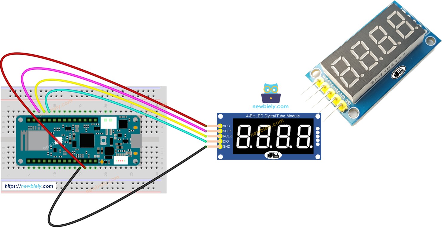
Wiring Diagram

Connect the display module to the MKR WiFi 1010:

  • SCLK to pin D3
  • RCLK to pin D2
  • DIO to pin D1
  • VCC to 3.3V (VCC pin on MKR)
  • GND to GND
The wiring diagram between Arduino MKR WiFi 1010 74HC595 4-Digit 7-Segment Display

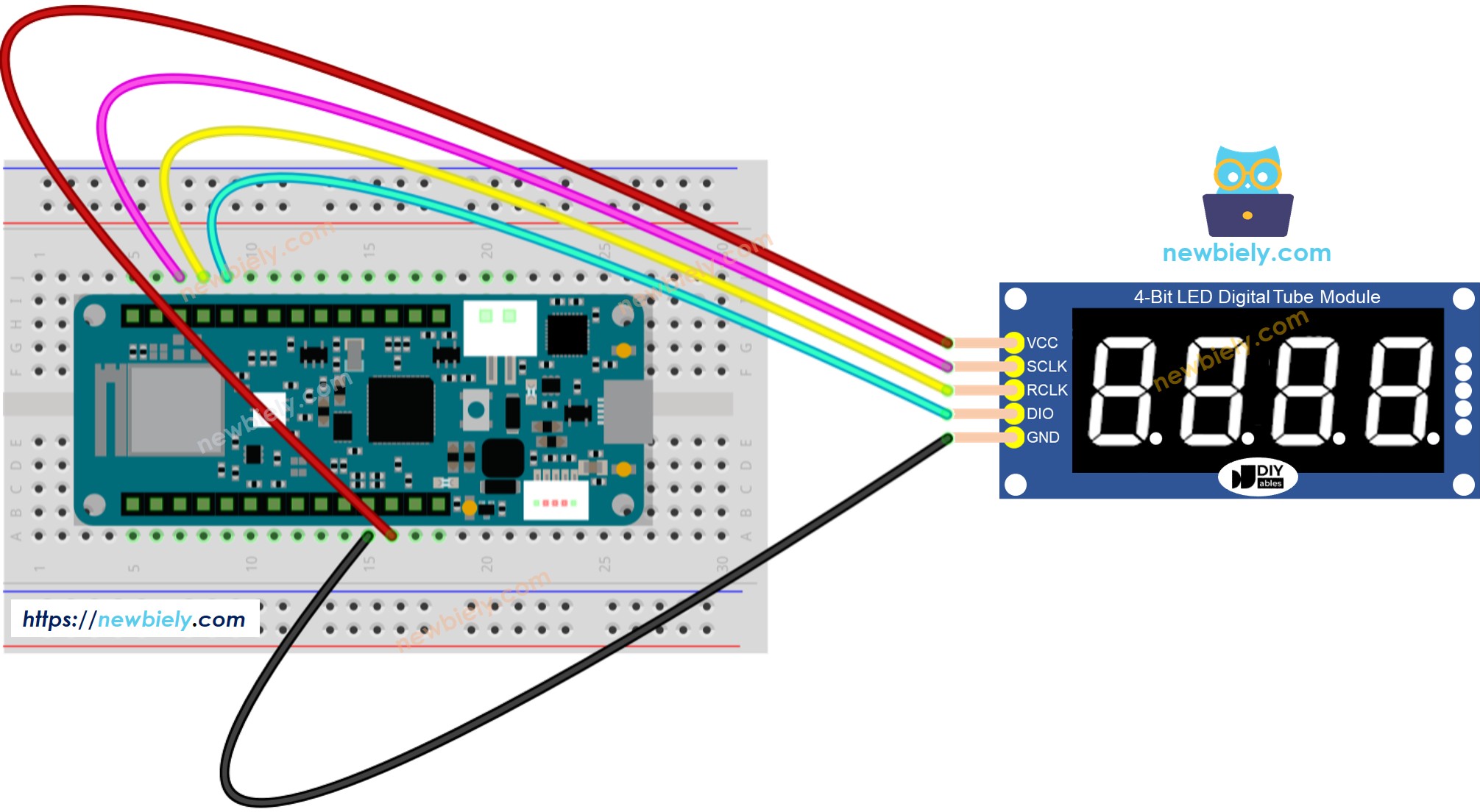
This image is created using Fritzing. Click to enlarge image

Installing the Library

  1. Connect the MKR WiFi 1010 to your computer with a Micro-B USB cable.
  2. Open Arduino IDE and select Arduino MKR WiFi 1010 from the board menu. Choose the correct port.
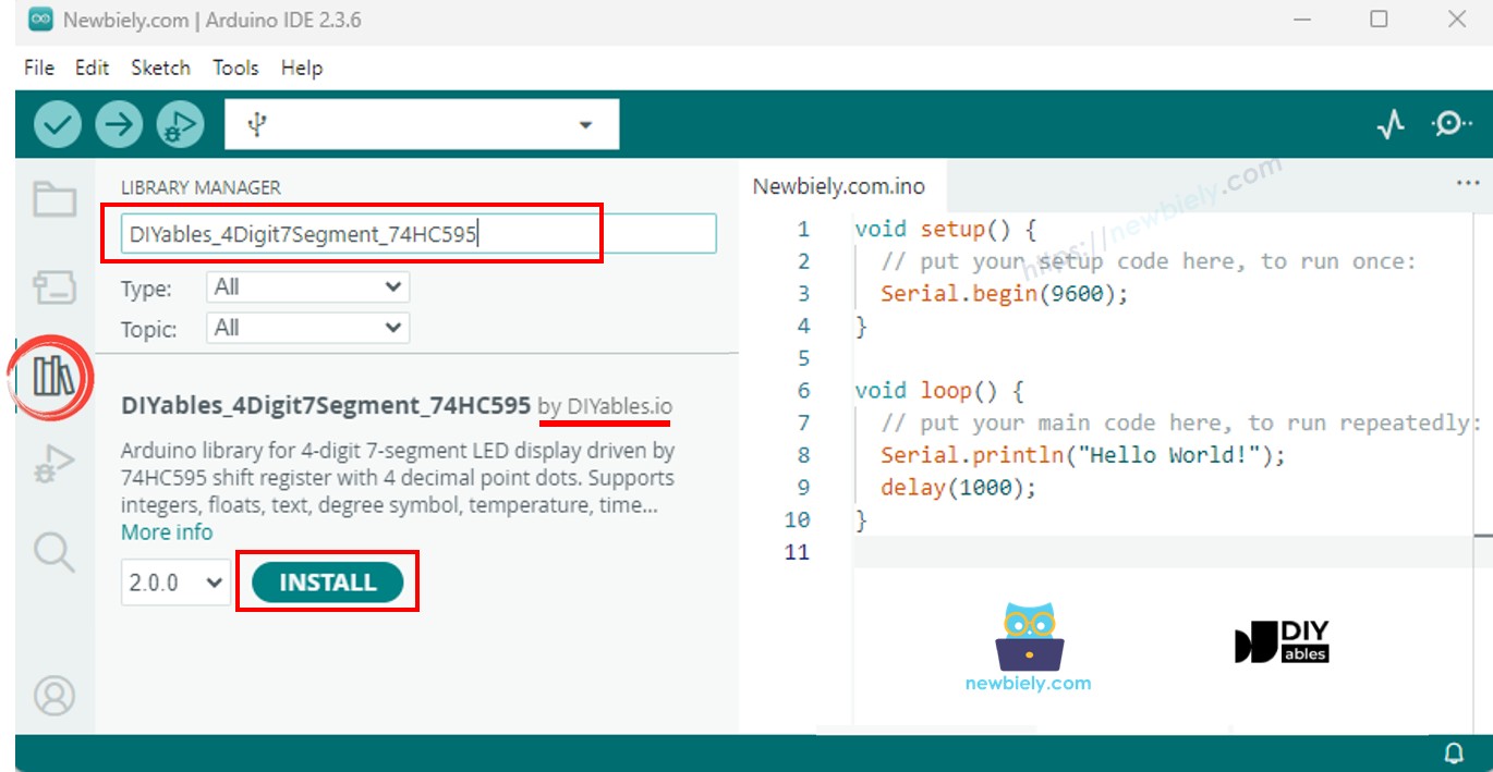
  3. Navigate to the Libraries panel.
  4. Search for "DIYables_4Digit7Segment_74HC595". Find the version published by DIYables.
  5. Click Install. Select version 2.0.0 or later.
Arduino MKR WiFi 1010 74HC595 4-Digit 7-Segment Display library

Fully self-contained - no additional libraries required.

Base Template

The simplest sketch you can write with the DIYables_4Digit7Segment_74HC595 library:

#include <DIYables_4Digit7Segment_74HC595.h> #define SCLK_PIN 3 #define RCLK_PIN 2 #define DIO_PIN 1 DIYables_4Digit7Segment_74HC595 display(SCLK_PIN, RCLK_PIN, DIO_PIN); void setup() { display.begin(); display.print(1234); } void loop() { display.loop(); }

Call begin() to configure the pins, set the value with print(), and keep calling display.loop() to run the multiplexing. Use display.delay() instead of delay() to avoid blanking the display.

Recipe - Display Integers

Shows integers and zero-padded values.

/* * This Arduino MKR WiFi 1010 code was developed by newbiely.com * * This Arduino MKR WiFi 1010 code is made available for public use without any restriction * * For comprehensive instructions and wiring diagrams, please visit: * https://newbiely.com/tutorials/arduino-mkr/arduino-mkr-wifi-1010-74hc595-4-digit-7-segment-display */ #include <DIYables_4Digit7Segment_74HC595.h> // Pin configuration - change these to match your wiring #define SCLK_PIN 3 // The Arduino MKR WiFi 1010 pin connected to the Serial clock pin of 7-segment display #define RCLK_PIN 2 // The Arduino MKR WiFi 1010 pin connected to the Register clock / latch pin of 7-segment display #define DIO_PIN 1 // The Arduino MKR WiFi 1010 pin connected to the Data (DS) pin of 7-segment display DIYables_4Digit7Segment_74HC595 display(SCLK_PIN, RCLK_PIN, DIO_PIN); int numbers[] = {0, 42, 1234, -5, -123, 9999}; int numCount = 6; int currentIndex = 0; bool showZeroPad = false; unsigned long lastChange = 0; void setup() { Serial.begin(9600); display.begin(); Serial.println("4-Digit 7-Segment 74HC595 - Integer Example"); } void loop() { display.loop(); // Must be called frequently to refresh the display if (millis() - lastChange >= 2000) { lastChange = millis(); if (!showZeroPad) { display.print(numbers[currentIndex]); Serial.print("Displaying: "); Serial.println(numbers[currentIndex]); currentIndex++; if (currentIndex >= numCount) { currentIndex = 0; showZeroPad = true; } } else { display.print(42, true); // Shows "0042" Serial.println("Displaying: 0042 (zero-padded)"); showZeroPad = false; } } }

Make It Happen

  • Wire the display to the MKR WiFi 1010 as shown above.
  • Plug the MKR WiFi 1010 into your computer via Micro-B USB.
  • Open Arduino IDE, confirm board and port, paste the code, then click Upload.
  • Open the Serial Monitor to check the output.

Cycles through 0, 42, 1234, -5, -123, 9999, and 0042 (zero-padded).

Quick API Reference

Method Behavior Code Snippet
print(int) Show an integer display.print(1234)
print(int, true) Show with leading zeros display.print(42, true)
loop() Run display multiplexing display.loop()

Recipe - Display Floats

Floats with auto and manual decimal places.

/* * This Arduino MKR WiFi 1010 code was developed by newbiely.com * * This Arduino MKR WiFi 1010 code is made available for public use without any restriction * * For comprehensive instructions and wiring diagrams, please visit: * https://newbiely.com/tutorials/arduino-mkr/arduino-mkr-wifi-1010-74hc595-4-digit-7-segment-display */ #include <DIYables_4Digit7Segment_74HC595.h> // Pin configuration - change these to match your wiring #define SCLK_PIN 3 // The Arduino MKR WiFi 1010 pin connected to the Serial clock pin of 7-segment display #define RCLK_PIN 2 // The Arduino MKR WiFi 1010 pin connected to the Register clock / latch pin of 7-segment display #define DIO_PIN 1 // The Arduino MKR WiFi 1010 pin connected to the Data (DS) pin of 7-segment display DIYables_4Digit7Segment_74HC595 display(SCLK_PIN, RCLK_PIN, DIO_PIN); void setup() { Serial.begin(9600); display.begin(); Serial.println("4-Digit 7-Segment 74HC595 - Float Example"); } void loop() { // Auto decimal placement display.print(1.5); // Shows " 1.5" Serial.println("Auto decimal: 1.5"); display.delay(2000); display.print(12.34); // Shows "12.34" Serial.println("Auto decimal: 12.34"); display.delay(2000); display.print(3.141); // Shows "3.141" Serial.println("Auto decimal: 3.141"); display.delay(2000); display.print(-1.2); // Shows "-1.20" Serial.println("Auto decimal: -1.20"); display.delay(2000); display.print(0.5); // Shows " 0.5" Serial.println("Auto decimal: 0.5"); display.delay(2000); // Fixed decimal places display.print(23.5, 1); // 1 decimal place: shows "23.5" Serial.println("1 decimal place: 23.5"); display.delay(2000); display.print(1.5, 2); // 2 decimal places: shows "1.50" Serial.println("2 decimal places: 1.50"); display.delay(2000); // Zero-padded display.print(1.5, 2, true); // Shows "01.50" Serial.println("2 decimal places, zero-padded: 01.50"); display.delay(2000); }

Make It Happen

  • Upload and open the Serial Monitor.

Shows auto-decimal floats, fixed 1 and 2 places, and zero-padded output.

Recipe - Text and Temperature

Text strings, degree symbol, and temperature display.

/* * This Arduino MKR WiFi 1010 code was developed by newbiely.com * * This Arduino MKR WiFi 1010 code is made available for public use without any restriction * * For comprehensive instructions and wiring diagrams, please visit: * https://newbiely.com/tutorials/arduino-mkr/arduino-mkr-wifi-1010-74hc595-4-digit-7-segment-display */ #include <DIYables_4Digit7Segment_74HC595.h> // Pin configuration - change these to match your wiring #define SCLK_PIN 3 // The Arduino MKR WiFi 1010 pin connected to the Serial clock pin of 7-segment display #define RCLK_PIN 2 // The Arduino MKR WiFi 1010 pin connected to the Register clock / latch pin of 7-segment display #define DIO_PIN 1 // The Arduino MKR WiFi 1010 pin connected to the Data (DS) pin of 7-segment display DIYables_4Digit7Segment_74HC595 display(SCLK_PIN, RCLK_PIN, DIO_PIN); const char* texts[] = {"HELP", "Hi", "COOL", "done"}; int textCount = 4; int currentIndex = 0; int phase = 0; unsigned long lastChange = 0; void setup() { Serial.begin(9600); display.begin(); Serial.println("4-Digit 7-Segment 74HC595 - Text and Degree Example"); } void loop() { display.loop(); // Must be called frequently to refresh the display if (millis() - lastChange >= 2000) { lastChange = millis(); if (phase == 0) { // Display text strings display.print(texts[currentIndex]); Serial.print("Text: "); Serial.println(texts[currentIndex]); currentIndex++; if (currentIndex >= textCount) { currentIndex = 0; phase = 1; } } else if (phase == 1) { // Display temperature 25 degrees C display.printTemperature(25, 'C'); Serial.println("Temperature: 25 C"); phase = 2; } else if (phase == 2) { // Display temperature 72 degrees F display.printTemperature(72, 'F'); Serial.println("Temperature: 72 F"); phase = 3; } else if (phase == 3) { // Display degree symbol using string with DEGREE_CHAR constant char degStr[5]; degStr[0] = '2'; degStr[1] = '5'; degStr[2] = DEGREE_CHAR; degStr[3] = 'C'; degStr[4] = '\0'; display.print(degStr); Serial.println("String with degree: 25 deg C"); phase = 4; } else { // Display string with dots display.print("1.2.3.4"); Serial.println("Dots: 1.2.3.4"); phase = 0; } } }

Make It Happen

  • Upload and open the Serial Monitor.

Displays "HELP", "Hi", "COOL", "done", temperature values, and inline dots.

Recipe - Time Display

Clock-format HH.MM with blinking dot.

/* * This Arduino MKR WiFi 1010 code was developed by newbiely.com * * This Arduino MKR WiFi 1010 code is made available for public use without any restriction * * For comprehensive instructions and wiring diagrams, please visit: * https://newbiely.com/tutorials/arduino-mkr/arduino-mkr-wifi-1010-74hc595-4-digit-7-segment-display */ #include <DIYables_4Digit7Segment_74HC595.h> // Pin configuration - change these to match your wiring #define SCLK_PIN 3 // The Arduino MKR WiFi 1010 pin connected to the Serial clock pin of 7-segment display #define RCLK_PIN 2 // The Arduino MKR WiFi 1010 pin connected to the Register clock / latch pin of 7-segment display #define DIO_PIN 1 // The Arduino MKR WiFi 1010 pin connected to the Data (DS) pin of 7-segment display DIYables_4Digit7Segment_74HC595 display(SCLK_PIN, RCLK_PIN, DIO_PIN); int hours = 12; int minutes = 30; bool colonOn = true; unsigned long lastToggle = 0; void setup() { Serial.begin(9600); display.begin(); Serial.println("4-Digit 7-Segment 74HC595 - Time Example"); Serial.println("Displaying 12:30 with blinking dot separator"); } void loop() { display.loop(); // Must be called frequently to refresh the display if (millis() - lastToggle >= 500) { lastToggle = millis(); display.printTime(hours, minutes, colonOn); colonOn = !colonOn; // Toggle dot separator every 500ms for blinking effect } }

Make It Happen

  • Upload and open the Serial Monitor.

Shows 12.30 with the dot blinking every 500ms.

Troubleshoot

  • Display blank: Check VCC, GND, and pin wiring. Verify begin() and display.loop() are in place.
  • Wrong characters: Default is common anode. For common cathode, pass false to the constructor.
  • Flickering: Replace delay() with display.delay().
  • Board not showing up: Install the Arduino SAMD Boards core through the Boards Manager if the MKR WiFi 1010 does not appear in the board list.

Platform Support

This library relies solely on Arduino standard APIs and is compatible with all Arduino-supported platforms (architectures=*).

※ OUR MESSAGES

  • As freelancers, We are AVAILABLE for HIRE. See how to outsource your project to us
  • Please feel free to share the link of this tutorial. However, Please do not use our content on any other websites. We invested a lot of effort and time to create the content, please respect our work!