
Raspberry Pi Pico - IR Slotted Optical Speed Sensor
In this guide, we will learn to set up and use the IR slotted optical speed sensor with the Raspberry Pi Pico. We will cover the following details:
- How the U-shaped sensor sees an object inside its slot.
- How to connect the speed sensor to a Raspberry Pi Pico.
- How to program the Raspberry Pi Pico to count every object that passes through the slot.
- How to program the Raspberry Pi Pico to turn the pulses of an encoder disc into a speed value in RPM.
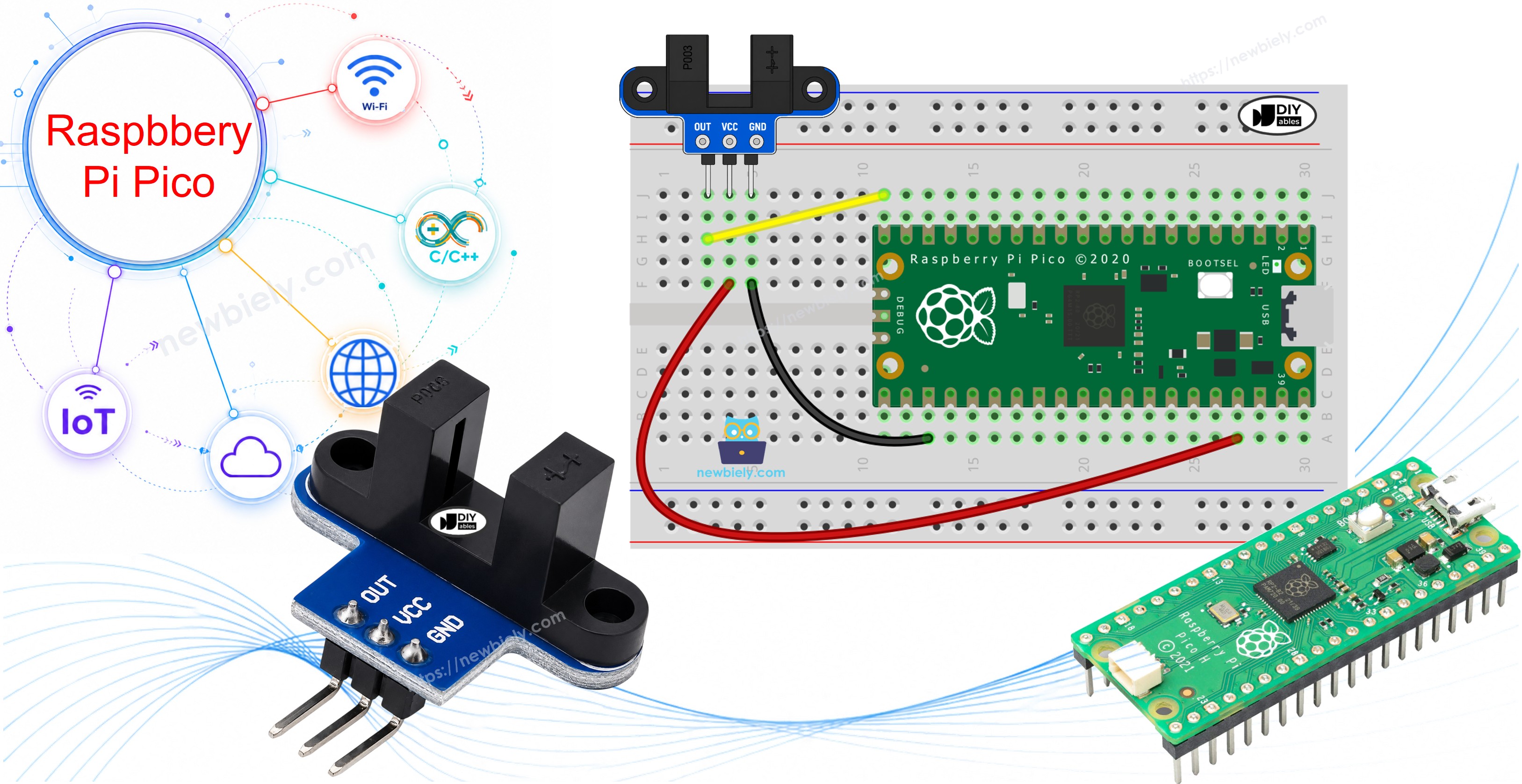
Hardware Preparation
Or you can buy the following kits:
| 1 | × | DIYables Sensor Kit (18 sensors/displays) |
Additionally, some of these links are for products from our own brand, DIYables .
Overview of IR Slotted Optical Speed Sensor
Look at this module from the side and you see the letter U. People call it by many names: photo interrupter, opto interrupter, slot sensor or U-shaped IR sensor. The job is always the same. It tells the Raspberry Pi Pico if something is sitting in the gap between its two arms.
With an encoder disc, the sensor becomes a tachometer. You can read the speed of a motor or a robot wheel, count turns to find a distance, count parts on a small belt, or use it as a limit switch that never touches anything.
| IR Slotted Optical Speed Sensor | |
|---|---|
| Sensor type | slot-type photoelectric (IR LED + NPN phototransistor) |
| Slot width | 5.9 mm |
| Operating voltage | 3.3V to 5V DC |
| Output | digital (TTL), LOW when blocked, HIGH when clear |
| Signal conditioning | built-in Schmitt trigger |
| Mounting | M3 screw holes at both ends |
| Pins | 3 (VCC, GND, OUT) |
Pinout
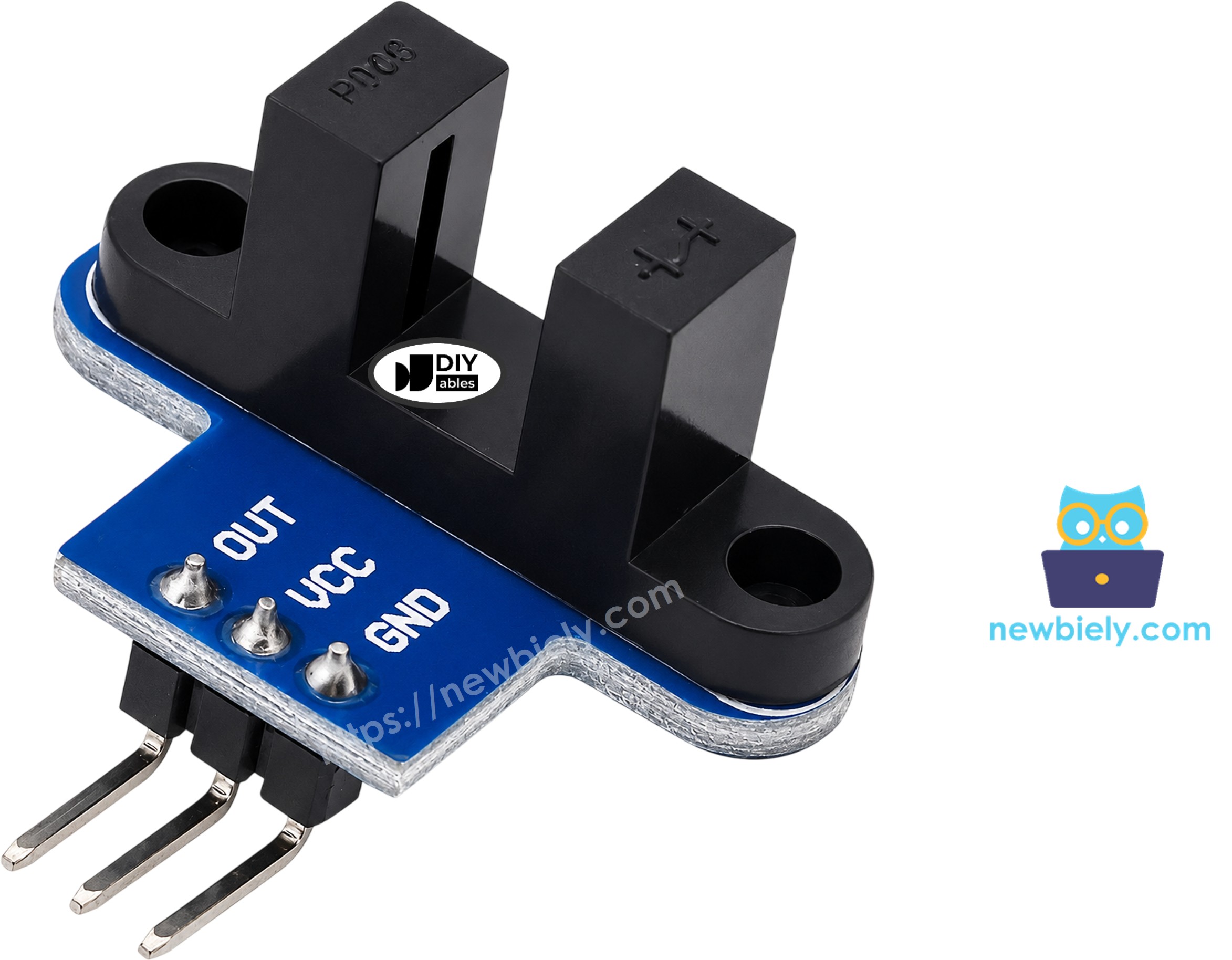
There are only three pins on the module:
- VCC pin: connect to the 3V3(OUT) pin of the Raspberry Pi Pico (3.3 volts). The module accepts 3.3 volts to 5 volts.
- GND pin: connect to any GND pin of the Raspberry Pi Pico (0 volts).
- OUT pin: connect to a GPIO pin of the Raspberry Pi Pico (GP15 in this guide). It gives a digital signal.
The pin order can change from one batch to the next. Read the small labels on your own module before you wire it.
Why not 5 volts? The OUT pin goes as high as the VCC voltage. The Pico is a 3.3 volts board, and its GPIO pins do not like 5 volts. So, feed the sensor from 3V3(OUT), and the signal will never go over 3.3 volts.
How It Works

One arm of the U holds an infrared LED. The other arm holds an NPN phototransistor. They face each other across the 5.9 mm slot.
- Slot empty: the infrared light gets to the phototransistor, and the OUT pin is HIGH (value 1 in MicroPython).
- Slot blocked: a card or a tooth of a disc stops the light, and the OUT pin is LOW (value 0).
A Schmitt trigger chip on the board shapes the signal. The Pico gets a sharp 0 or 1, with no shaky in-between values, so the code needs no debounce.
Keep two things in mind:
- Use an opaque object. A clear piece of plastic can let the infrared light pass, and the sensor will not see it.
- A few modules from other brands work the other way round. If the Shell says "blocked" while the slot is empty, swap the 0 and 1 checks in the first script. The RPM script counts one edge per tooth, so it works with both types.
Wiring Diagram
The built-in Schmitt trigger already gives a clean signal, so you need no extra resistor; just take power from the 3.3 volts pin of the Pico.
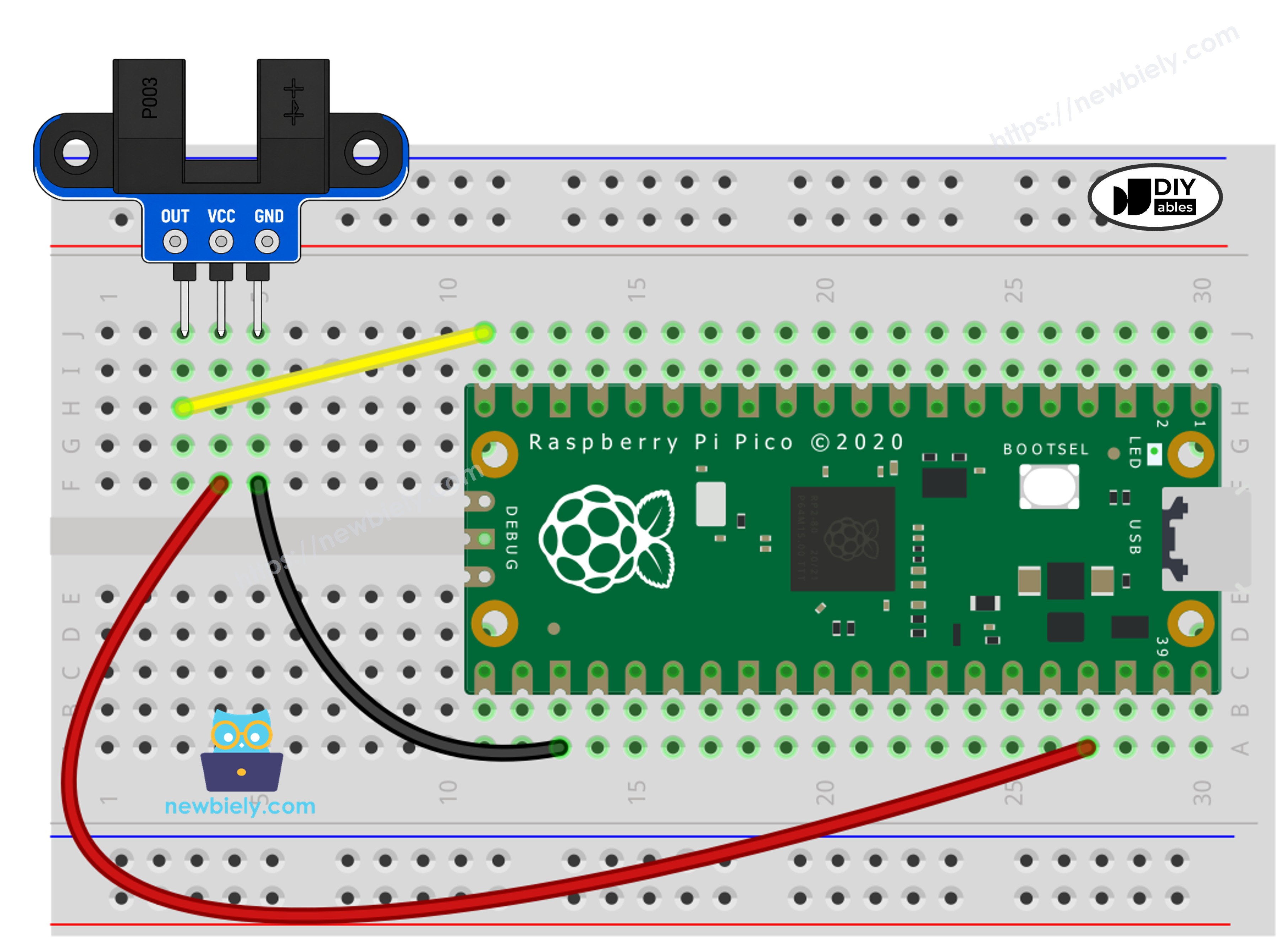
This image is created using Fritzing. Click to enlarge image
Raspberry Pi Pico Code - Count Objects in the Slot
The first script checks the OUT pin again and again. It prints a line only when the state changes. Each time the slot goes from clear to blocked, the counter goes up by one.
Detailed Instructions
Please follow these instructions step by step:
- Ensure that Thonny IDE is installed on your computer.
- Ensure that MicroPython firmware is installed on your Raspberry Pi Pico.
- If this is your first time using a Raspberry Pi Pico, refer to the Raspberry Pi Pico - Getting Started tutorial for detailed instructions.
- Wire the speed sensor to the Raspberry Pi Pico according to the provided diagram. Double-check that VCC goes to 3V3(OUT), not to VBUS.
- Connect the Raspberry Pi Pico to your computer using a Micro USB cable.
- Launch the Thonny IDE on your computer.
- On Thonny IDE, select MicroPython (Raspberry Pi Pico) Interpreter by navigating to Tools Options.
- In the Interpreter tab, select MicroPython (Raspberry Pi Pico) from the drop-down menu.
- Ensure the correct port is selected. Thonny IDE should automatically detect the port.
- Copy the above code and paste it to the Thonny IDE's editor.
- Save the script to your Raspberry Pi Pico by:
- Click the Save button, or use Ctrl+S keys.
- In the save dialog, select Raspberry Pi Pico.
- Save the file as main.py
- Click the green Run button (or press F5) to run the script.
- Slide a piece of card down into the slot, then pull it out. Do it three times. Your finger works too.
- Check out the message in the Shell at the bottom of Thonny.
If you name your script main.py and save it to the root directory of the Raspberry Pi Pico, it will automatically run each time the Pico is powered on or reset.
Raspberry Pi Pico Code - Measure Motor Speed (RPM)
Now, let's measure how fast something spins. For this, you need an encoder disc: a thin wheel with slots cut around its edge. Fix the disc on the motor shaft or on the wheel. Its teeth must pass through the slot of the sensor without rubbing on it.
A spinning disc makes pulses very fast. A simple loop that reads the pin could miss some of them. So this script uses an interrupt. With Pin.irq() and Pin.IRQ_FALLING, MicroPython calls a small function at the moment the signal drops from HIGH to LOW. That happens once for each tooth that enters the slot, so one tooth gives exactly one count.
Once per second, the main loop takes the count and sets it back to zero. Then it does the math:
- The disc in this example has 20 slots, so one full turn gives 20 pulses.
- Pulses in 1 second × 60 = pulses in 1 minute.
- Pulses in 1 minute ÷ 20 = turns in 1 minute, which is the RPM.
The 20-slot disc is the one that often comes with TT gear motors. If your disc has a different number of slots, change SLOTS_PER_TURN at the top of the script.
Detailed Instructions
The wiring stays the same. Only the script changes:
- Copy the code above into a new tab in Thonny.
- Save it to the Raspberry Pi Pico as main.py. This replaces the first script.
- Click the green Run button (or press F5).
- Spin the disc with your hand, or let the motor turn it. To drive a motor from the Pico, see the Raspberry Pi Pico - DC Motor tutorial.
- Check out the message in the Shell at the bottom of Thonny. A new line shows up every second.
In this run, the motor turned at about 300 RPM, and then it stopped. The value moves up and down a little because the count window is one second long. A wheel can also tell you distance: one turn moves the robot by the wheel's circumference (π × diameter), so total distance = number of turns × π × diameter.
Do you want to sense an object from a few centimeters away, not inside a slot? Try the Raspberry Pi Pico - Obstacle Avoidance Sensor tutorial. For a knob that also tells the turning direction, see the Raspberry Pi Pico - Rotary Encoder tutorial.