
Raspberry Pi Pico - PC817 Optocoupler: Monitor 12V/24V DC Input Signal
In this guide, we will learn to set up and use the PC817 optocoupler with the Raspberry Pi Pico. We will cover the following details:
- Which PC817 optocoupler module to buy for the signal you want to watch, because the module comes in three input variants.
- How to wire a PC817 optocoupler module to a Raspberry Pi Pico so the board can safely watch a 3.3V, 5V, 12V or 24V DC line.
- How to tap the module across a device so the Raspberry Pi Pico knows whether that device is actually running.
- How to find out whether your module reads active LOW or active HIGH, and how to flip the code with one line.
- How to program the Raspberry Pi Pico to read the isolated digital input in MicroPython.
- How to build the same input from the bare PC817 chip and a series resistor, if you would rather.
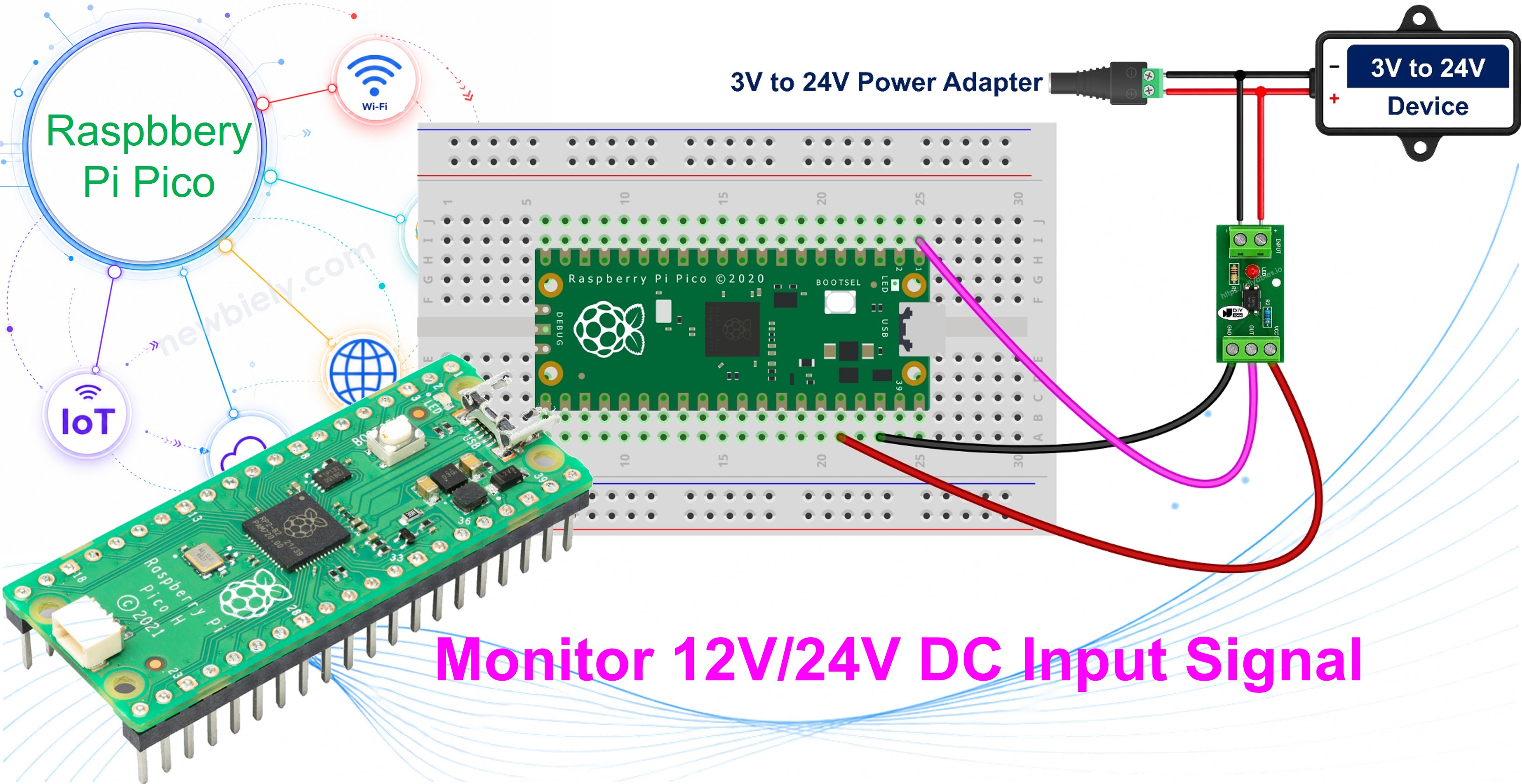
The Raspberry Pi Pico is small, inexpensive and needs very little power, so it is a great board to leave permanently wired to one machine as a tiny standalone watcher. The question such a watcher really answers is not whether a voltage is present, but whether the device on the other end is actually running right now. Two projects this guide is aimed at: counting the cycles of a machine that reports each stroke on a 24V PLC output, and watching the 12V position signal of a gate or barrier controller so you always know whether it is open or shut. Both of those signals are far too high for a Raspberry Pi Pico to touch directly, and the PC817 is what makes them readable.
Hardware Preparation
Or you can buy the following kits:
| 1 | × | DIYables Sensor Kit (18 sensors/displays) |
Additionally, some of these links are for products from our own brand, DIYables .
Overview of PC817 Optocoupler
The PC817, also sold as a photocoupler or an opto-isolator, is a 4-pin chip that carries a signal from one circuit to another without any wire between them. Inside the plastic body there is an infrared LED pointing at a phototransistor across an insulating gap. When current flows through the LED, its light switches the transistor on, so the signal crosses as light instead of electricity. That is the whole reason the two sides stay electrically separate, and it is why a Raspberry Pi Pico can watch a 24V industrial line without ever being wired to it.
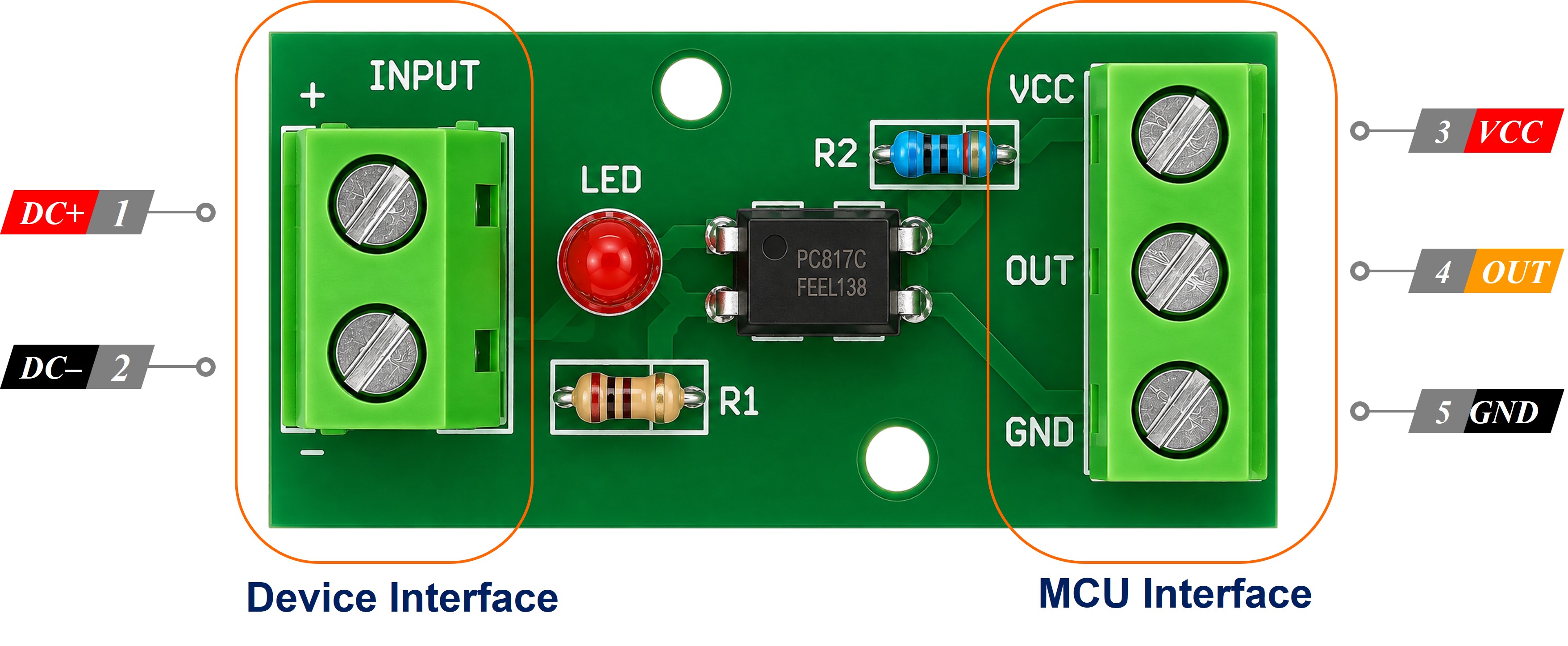
Most people never solder the chip itself. A PC817 optocoupler isolation module puts that chip on a small board together with its series resistor and a status LED, brings the input side out to screw terminals marked IN+ and IN-, and brings the output side out to a header marked VCC, GND and OUT. That is the version this guide wires up, and modules come in 1, 2, 4 and 8 channel versions, which is handy when one Raspberry Pi Pico has to watch several isolated lines at once.
| PC817 | |
|---|---|
| Package | 4-pin DIP (pin 1 marked by a dot or a notch) |
| LED Forward Voltage (Vf) | about 1.2 V typical, 1.4 V max |
| LED Forward Current (If) | 20 mA continuous max, 5 to 20 mA normal |
| Collector-Emitter Voltage (VCEO) | 35 V max |
| Collector Current (IC) | 50 mA max |
| Collector Power Dissipation | 150 mW |
| Isolation Voltage | 5000 Vrms for 1 minute |
| Current Transfer Ratio (CTR) | 50% to 600% depending on rank |
| Switching Speed | rise about 4 µs, fall about 3 µs |
| Operating Temperature | -30°C to +100°C |
Which Optocoupler Module Do I Need?
Because the resistor that feeds the internal LED is already fitted to the board, one module cannot cover every input voltage. The modules are sold as three separate variants, and the resistor on each one is chosen for that variant's voltage. Buy the variant that matches the signal you intend to watch:
| Signal you want to watch | Module to buy |
|---|---|
| A 24 volt DC signal, such as a PLC output | 24V module |
| A 12 volt DC signal, such as a gate or barrier lamp | 12V module |
| A 3.3 volt or 5 volt logic signal | 3-5V module |
Getting this right is the one purchase decision that matters here. With a module you never calculate anything; you choose the correct variant and wire it up. Get it wrong in either direction and you will notice:
- Run a 12V module from a 24 volt line and roughly double the intended current goes through its internal LED, which will damage it.
- Run a 24V module from a 12 volt line and the LED is underdriven, so the output may switch late, switch unreliably, or never switch at all.
Low voltage is not a reason to skip the isolation and reach for a plain jumper wire. A 5 volt or 3.3 volt logic signal is worth isolating whenever the two circuits run from separate supplies, sit at opposite ends of a long cable, or one of them is electrically noisy, such as a motor driver or the low-voltage control board buried inside a mains-powered appliance. Isolation is about breaking the ground path, not only about surviving a high voltage. That is what the 3-5V module is for.
Pinout
The PC817 has four pins. Pins 1 and 2 belong to the input side, which faces the 12V or 24V circuit and which a module brings out to the IN+ and IN- terminals. Pins 3 and 4 belong to the output side, which faces the Raspberry Pi Pico and which a module brings out to its VCC, GND and OUT header.
- Pin 1 - Anode (A): the positive leg of the internal LED. The 12V or 24V signal reaches this pin through the series resistor, which is already on the board of a module.
- Pin 2 - Cathode (K): the negative leg of the internal LED. Connect to the ground of the 12V or 24V circuit, not to the ground of the Raspberry Pi Pico.
- Pin 3 - Emitter (E): the phototransistor emitter on the output side. Connect to a GND pin (0 volts) of the Raspberry Pi Pico.
- Pin 4 - Collector (C): the phototransistor collector on the output side. Connect to a GPIO input pin of the Raspberry Pi Pico with the internal pull-up to 3.3 volts turned on.
How It Works
On the output side the collector is held up by the internal pull-up of the Raspberry Pi Pico, so the pin idles at 3.3 volts. As soon as the external signal appears, the LED lights, the phototransistor conducts, and it drags the pin down to 0 volts.
- External 12V or 24V signal PRESENT: the LED is on, the transistor conducts, and the GPIO pin reads LOW.
- External 12V or 24V signal ABSENT: the LED is off, the transistor is off, and the GPIO pin reads HIGH.
The reading is therefore inverted, which surprises most people the first time. A LOW reading means the signal is there, not missing. Our MicroPython code flips it back with a single comparison so that the rest of the program can stay readable. If you have already worked through the Raspberry Pi Pico - Button tutorial, this is exactly the same active-LOW pattern you used there, only now the switching is done by light instead of by a metal contact.
Optocoupler Module Active High or Active Low
Everything above is settled physics for the bare chip wired as shown. A module is a different matter: some makers add a transistor stage that inverts the signal again on the board, so the OUT pin follows the input instead of opposing it. Both kinds are on sale, they look identical, and nothing on the silkscreen tells you which one you are holding. Find out before you trust the reading.
This matters more on this page than on most, because the plan is to leave the Raspberry Pi Pico running as a cycle counter in a cabinet. A module of the opposite polarity does not fail loudly - it counts the gaps instead of the strokes, so it happily records exactly the wrong half of every cycle and the number still looks plausible on the screen. Two minutes in the Thonny Shell now saves you from screwing the lid down on a counter that has been lying since the day it was installed.
With the module wired and the Raspberry Pi Pico connected, click the red Stop button in Thonny so no script is running, then type these three lines into the Shell at the bottom of the window:
Leave the input terminals unpowered and press Enter on the last line: note the number the Shell prints back. Now apply the signal to IN+ and IN-, press the Up arrow to bring that same line back, and press Enter again. The value that appears while the signal is present is the active level of your module. The status LED on the module is your cross-check, because it lights whenever the input side is energised - if the LED is on and the pin still reads 1, your module is active HIGH.
There is one line to change in the code below. MODULE_ACTIVE_LOW is set to True, which suits the common modules and the bare chip. If your test says the Shell prints 1 while the signal is present, set it to False and nothing else in the script has to move.
The Two Grounds Stay Apart
This is the part that protects your board, so read it twice. Do NOT connect the ground of the 12V or 24V circuit to the GND of the Raspberry Pi Pico. The 12V/24V ground belongs to the IN- terminal of the module, or to pin 2 of a bare chip, and stops there. The Raspberry Pi Pico ground belongs to the GND pin of the output header, or to pin 3 of a bare chip, and stops there. Keeping those two grounds apart is the whole point of the chip. If you tie them together the PC817 will still switch and your code will still print the right thing, but the isolation is gone and a fault on the machine side now has a path straight into your Raspberry Pi Pico. When you only want to scale a voltage down rather than isolate it, a divider such as the one in the Raspberry Pi Pico - Measure Voltage tutorial is the right tool instead.
Keeping the Output Side at 3.3 Volts
The Raspberry Pi Pico is a 3.3V board and its GPIO pins are not 5V tolerant. Anything you feed into a GPIO pin has to stay at or below 3.3 volts. That is easy to respect here, because the phototransistor only ever pulls the pin down towards 0 volts and never pushes anything into it. Take the VCC of the module from the 3V3(OUT) pin of the Raspberry Pi Pico, which is physical pin 36. Do not take it from VBUS or VSYS, because those sit near 5 volts and the module would then drive its OUT pin to 5 volts. This applies to modules that invert on-board as well, and those are the ones that actively drive the OUT pin high, so the rail you feed them is exactly the voltage that lands on GP0.
Wiring Diagram
Wire the components as shown below, with the module variant that matches the line you are watching.
Raspberry Pi Pico - PC817 Optocoupler Module Wiring
The output header goes to the Raspberry Pi Pico: VCC to 3V3(OUT) on physical pin 36, GND to any GND pin, and OUT to GP0, which is physical pin 1. The screw terminals go to the isolated circuit: IN+ to the positive side of the signal and IN- to its return. There is no resistor to fit, because the module already carries the one that suits its variant.
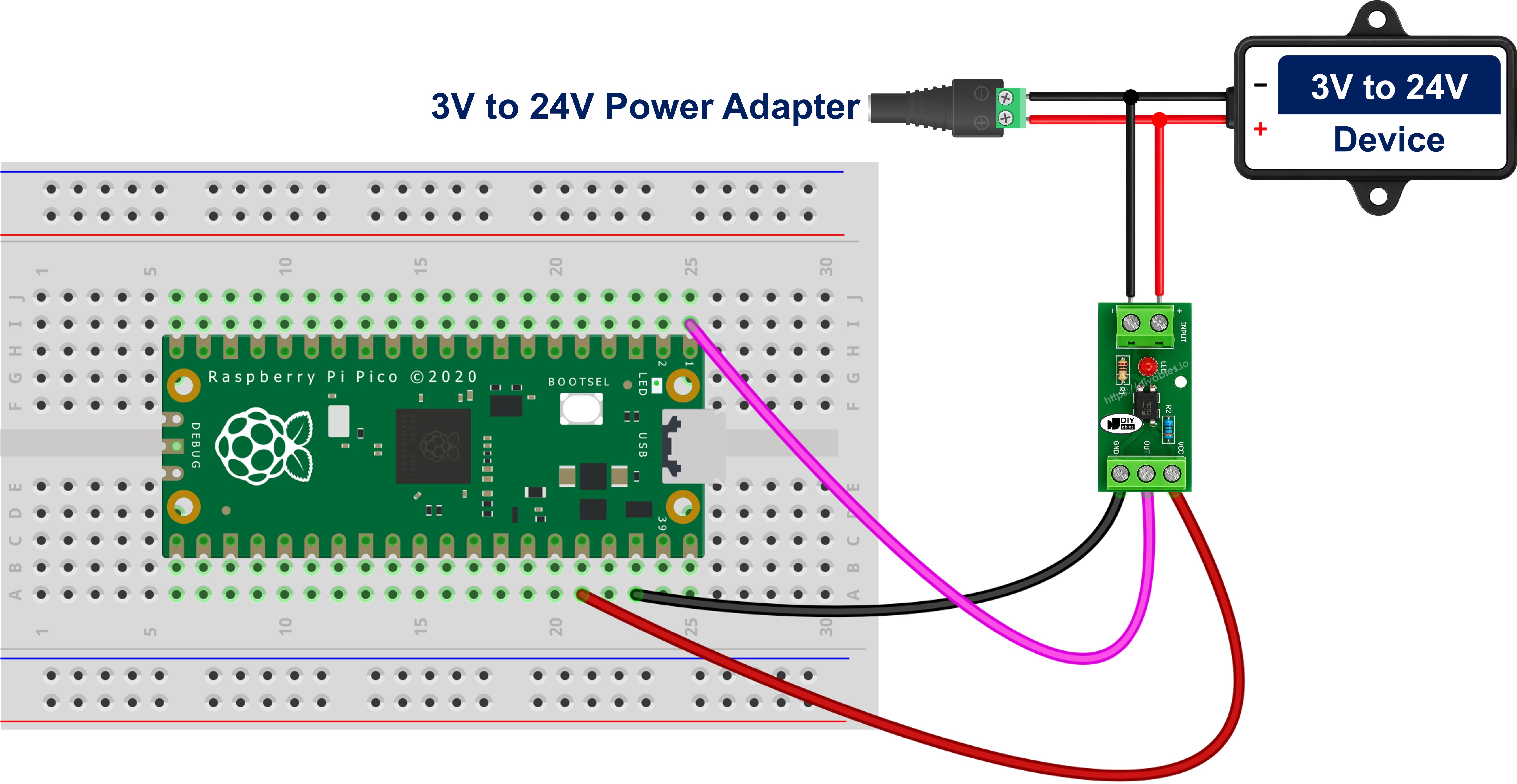
This image is created using Fritzing. Click to enlarge image
Wiring the Module in Parallel With a Device to Know If It Is Running
So far this guide has talked about a signal, but what you usually have in front of you is a device, and the real question is whether that device is running. Take the 12V gate or barrier controller from the start of the page. Its position output feeds a 12V indicator lamp that is lit whenever the barrier is up. You leave that lamp wired exactly as the installer left it, and you hang a 12V module across it:
- The positive, switched terminal of the lamp goes to the IN+ terminal of the module.
- The negative, return terminal of the lamp goes to the IN- terminal of the module.
Nothing in the controller is cut and nothing is rerouted, and nothing goes between the lamp and its supply. The module sits in parallel with the device, never in series with it. Wiring it in series would send the whole load current of the lamp, coil or motor through the internal LED, which is rated for 20 mA, and the chip would be gone the instant the device switched on. The parallel tap draws only about 10 mA, which is nothing beside what a lamp, relay coil, valve or motor already pulls, so the barrier controller carries on behaving exactly as it did before. This is a read-only measurement.
Because the tap follows the device itself and not the button or the controller output that commanded it, the Raspberry Pi Pico sees the real state: the barrier rising because a car triggered the loop, someone raising it by hand at night, or the barrier failing to move at all when it should have. That is what turns the reading into something worth logging - run hours, cycle counts, idle time, and did-it-actually-start alerts all fall out of the same single bit. One honest limitation: this tells you the device is energised, not that it is working, so a seized gate motor or a burnt-out lamp still draws power and still reads as running.
A few things to sort out before you power the tap up:
- Polarity matters: the input side of the module is an LED and conducts in one direction only. Swap IN+ and IN- and it will simply never turn on, so work out which side of the tap is positive first.
- Inductive loads need a clamp diode: a relay coil, solenoid, contactor, valve or motor throws a large reverse-voltage spike when it switches off, and the PC817 input LED will only stand 6 volts in reverse. Fit an ordinary diode in reverse-parallel directly across the two input terminals, cathode to IN+ and anode to IN-. In normal operation it is reverse-biased and does nothing; on a spike it conducts and clamps the reverse voltage to well under a volt. A 1N4148 suits a small tap, a 1N4007 a heavier one.
- Leaky solid-state outputs cause false readings: PLC transistor outputs, triac outputs and LED-lamp drivers often leak a little current even when they are switched off, and enough leakage part-lights the PC817 LED, so the Raspberry Pi Pico reports the device as running when it is not. The symptom is a reading that never goes back to idle. Fit a bleeder resistor of about 4.7 kohm to 10 kohm across the input terminals and the leakage flows through that instead of through the LED.
- DC only: the input is a single LED, so it responds to one polarity, and it is the wrong part for sensing an AC line, which needs an optocoupler whose input stage has two back-to-back LEDs.
If You Would Rather Build It From the Bare Chip
A bare PC817 costs a few cents and does the same job on a breadboard, but then the series resistor on pin 1 is yours to size, using the pinout above. The rule is R = (Vin - 1.2) / 0.01, taking 1.2 volts as the LED drop and 10 mA as the target current, which gives:
- 3.3 volt input: 220 ohm
- 5 volt input: 390 ohm
- 12 volt input: 1 kohm
- 24 volt input: 2.2 kohm, and use a 1/2 W part here because it dissipates about 0.24 W
Pin 3 goes to a GND pin of the Raspberry Pi Pico and pin 4 to GP0, exactly as the module's GND and OUT do. Change the resistor whenever you change the voltage you are watching: leaving a 1 kohm resistor in place when you move from a 12V circuit to a 24V one pushes about 22.8 mA through an LED rated for 20 mA. Wired this way the chip is always active LOW, so the code below needs no change.
Raspberry Pi Pico Code - PC817 Optocoupler
No library is needed. Reading a PC817 is plain digital input reading, so the whole program is a pull-up, a comparison and a print.
Detailed Instructions
Please follow these instructions step by step:
- Ensure that Thonny IDE is installed on your computer.
- Ensure that MicroPython firmware is installed on your Raspberry Pi Pico.
- If this is your first time using a Raspberry Pico, refer to the Raspberry Pi Pico - Getting Started tutorial for detailed instructions.
- Use the module variant that matches your signal: the 3-5V module for a 3.3V or 5V logic signal, the 12V module for a 12V signal, the 24V module for a 24V signal.
- Wire the components according to the provided diagram, keeping the 12V/24V ground away from the Raspberry Pi Pico GND.
- Connect the Raspberry Pi Pico to your computer using a USB cable.
- Launch the Thonny IDE on your computer.
- On Thonny IDE, select MicroPython (Raspberry Pi Pico) Interpreter by navigating to Tools Options.
- In the Interpreter tab, select MicroPython (Raspberry Pi Pico) from the drop-down menu.
- Ensure the correct port is selected. Thonny IDE should automatically detect the port, but you may need to select it manually (e.g., COM3 on Windows or /dev/ttyACM0 on Linux).
- Copy the above code and paste it to the Thonny IDE's editor.
- If your polarity test said the Shell prints 1 while the signal is present, set MODULE_ACTIVE_LOW to False before you save.
- Save the script to your Raspberry Pi Pico by:
- Click the Save button, or use Ctrl+S keys.
- In the save dialog, you will see two sections: This computer and Raspberry Pi Pico. Select Raspberry Pi Pico
- Save the file as main.py
- Click the green Run button (or press F5) to run the script. The script will execute.
- Switch the 12V or 24V signal on, leave it on for a few seconds, then switch it off again.
- Check out the message in the Shell at the bottom of Thonny.
If the SIGNAL PRESENT lines appear while the signal is off and the IDLE lines while it is on, you have an active-HIGH module and the fix is the one line above, not a rewrite.
If you name your script main.py and save it to the root directory of the Raspberry Pi Pico, it will automatically run each time the Pico is powered on or reset. That matters for this project more than for most, because a device watcher is meant to be left in a cabinet next to the machine with nothing but a USB charger for power. Left like that, with a counter added to the code, the Raspberry Pi Pico becomes a permanent cycle counter that can say whether the machine ran today and how many times it ran, without anyone plugging a laptop into it. Confirm the polarity before the cabinet is closed, because a counter that has been counting the wrong half of every cycle looks exactly like a working one from the outside. If you name your script anything other than main.py, you will need to start it by hand from Thonny's Shell every time.
From here the same input can drive an action instead of a print. Feeding the isolated reading into the Raspberry Pi Pico - Relay tutorial turns the watcher into a small controller that reacts to the 24V line on its own.