
Raspberry Pi Pico - DRV8833 DC Motor Driver
In this guide, we will learn to set up and use the DRV8833 motor driver with the Raspberry Pi Pico. The DRV8833 is a tiny board, so it fits well on a breadboard next to the Pico, and it runs happily from a 3 to 9 volt battery pack. We will cover the following details:
- What each pin of the DRV8833 module does, and how its four input states (coast, forward, reverse, brake) work.
- How to wire one DC motor to the Raspberry Pi Pico through the DRV8833, and write MicroPython code to change its speed and direction.
- How to add a second DC motor and drive both of them like the wheels of a small robot car.
If you only want the basics of DC motors with the bigger L298N board, see the Raspberry Pi Pico - DC Motor tutorial.
Hardware Preparation
Or you can buy the following kits:
| 1 | × | DIYables Sensor Kit (18 sensors/displays) |
Additionally, some of these links are for products from our own brand, DIYables .
Overview of DRV8833 Motor Driver
A GPIO pin of the Pico gives only a few milliamps, which is far too weak to spin a motor. The DRV8833 (a chip made by Texas Instruments) sits in the middle: the Pico sends small 3.3 volt signals, and the chip switches the real motor current from a separate power supply. It has two H-bridges inside, so one module can run two brushed DC motors (or one small bipolar stepper motor). Its outputs use MOSFETs with low resistance, so it wastes much less voltage and makes much less heat than the older L298N.
| DRV8833 Module | |
|---|---|
| Motor Supply Voltage (VCC) | 2.7 volts to 10.8 volts |
| Logic Signal Voltage | 3.3 volts or 5 volts (no separate logic supply needed) |
| Output Current | about 1.5 A per channel, 2 A peak (with good cooling) |
| Number of Channels | 2 (motor A and motor B) |
| PWM Frequency | up to 50 kHz |
| Protection | under-voltage lockout, over-current, thermal shutdown |
Pinout
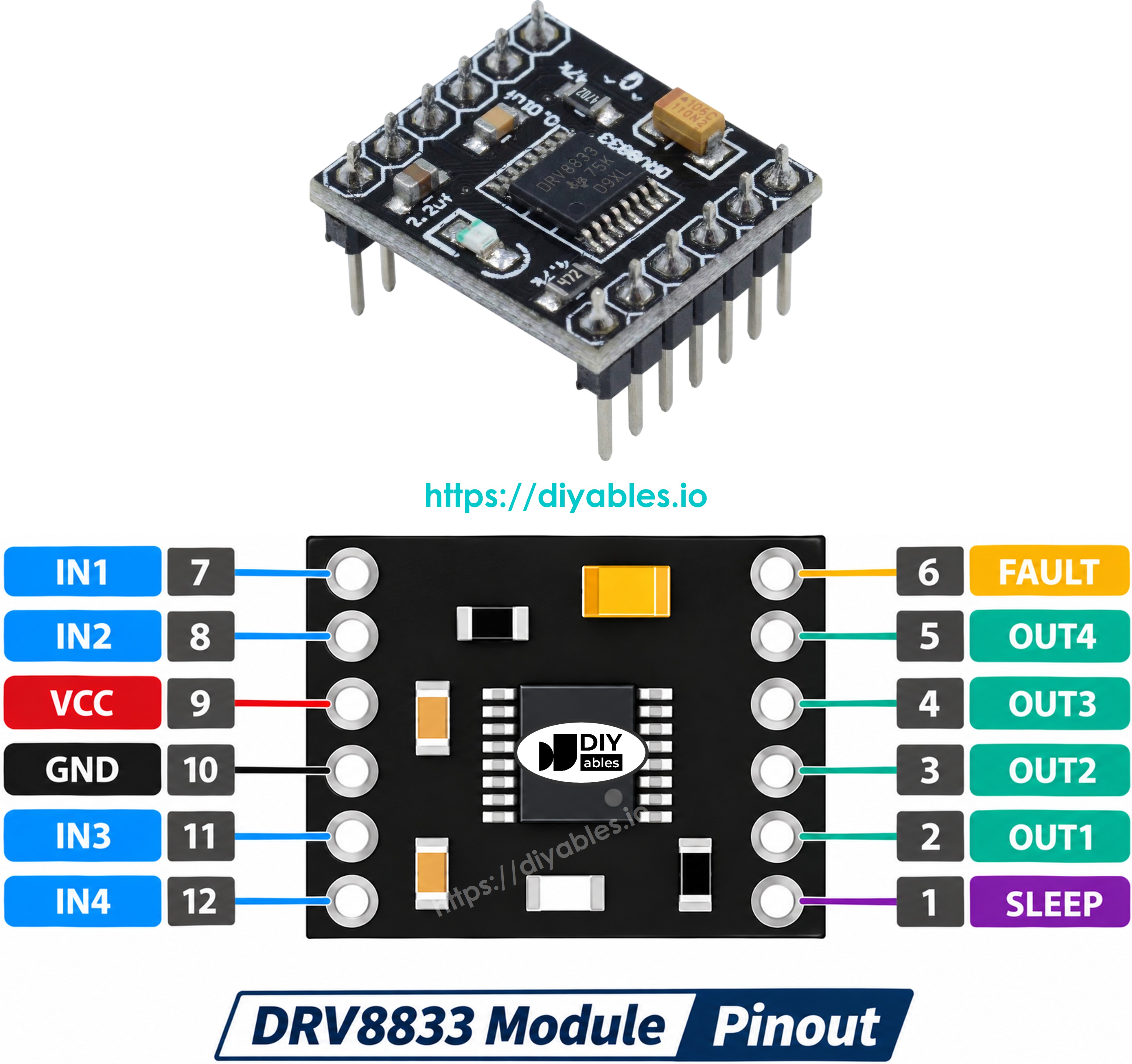
The common red or blue DRV8833 breakout has these pins. The labels vary between sellers (some print AIN1/AIN2/BIN1/BIN2, AOUT1/AOUT2/BOUT1/BOUT2, SLP and FLT), but the jobs are the same:
- VCC pin: connect to the motor power supply (2.7 volts to 10.8 volts). The chip makes its own logic voltage from this pin.
- GND pin: connect to GND (0 volts). This ground must be shared with the Pico and the motor supply.
- IN1, IN2 pins: control motor A. Connect to two PWM-capable GPIO pins of the Pico.
- IN3, IN4 pins: control motor B. Connect to two more PWM-capable GPIO pins.
- OUT1, OUT2 pins: connect to the two wires of motor A.
- OUT3, OUT4 pins: connect to the two wires of motor B.
- EEP pin (nSLEEP): connect to 3.3 volts to turn the driver on. If it is LOW, the chip sleeps and the motors do not move.
- ULT pin (nFAULT): goes LOW when the chip finds a fault (too hot, too much current, too low voltage). It is optional, you can leave it unconnected.
How the IN Pins Control a Motor
Unlike the L298N, the DRV8833 has no ENA/ENB speed pin. Each motor is controlled only by its pair of IN pins:
| IN1 (or IN3) | IN2 (or IN4) | What the motor does |
|---|---|---|
| LOW | LOW | Coast - the motor is free and slowly rolls to a stop |
| HIGH | LOW | Spins forward |
| LOW | HIGH | Spins in reverse |
| HIGH | HIGH | Brake - the motor stops quickly |
To change the speed, the code sends a PWM signal to one IN pin and keeps the other pin LOW. For forward, the PWM goes to IN1 (or IN3). For reverse, the PWM goes to IN2 (or IN4). This is why both IN pins of a motor must be PWM pins. On the Pico this is easy: every GP pin can make PWM, and MicroPython sets the duty with duty_u16(), from 0 (off) to 65535 (full speed).
PART 1: Control One DC Motor
Wiring Diagram
In this part, the motor uses channel B of the DRV8833: it connects to OUT3 and OUT4, and the Pico drives it through IN3 and IN4. The motor gets its power from the 5 volt adapter through the DC power jack, not from the Pico. The Pico only sends the control signals. Make sure the GND of the adapter, the DRV8833 and the Pico are all connected together.
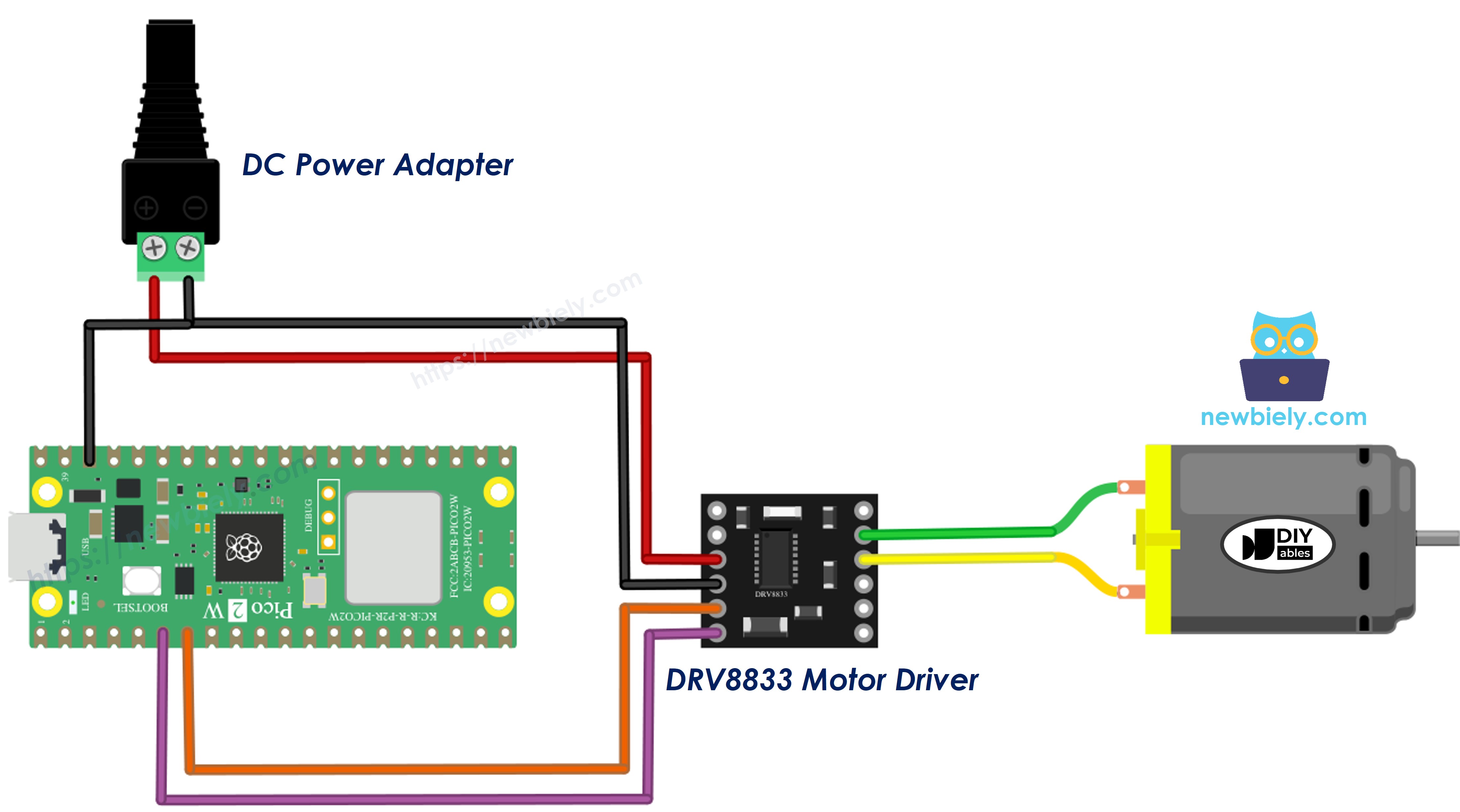
This image is created using Fritzing. Click to enlarge image
| DRV8833 Module | Raspberry Pi Pico / Other |
|---|---|
| IN3 | GP5 (pin 7) |
| IN4 | GP4 (pin 6) |
| EEP | 3V3(OUT) (pin 36) |
| GND | GND (pin 38) and the minus (-) of the DC power jack |
| VCC | the plus (+) of the DC power jack (5 volt adapter) |
| OUT3, OUT4 | the two wires of the DC motor |
※ NOTE THAT:
Do not power the motor from the 3V3(OUT), VSYS or VBUS pin of the Pico. A motor pulls a big current when it starts, and this can reset the Pico or damage the USB port.
Raspberry Pi Pico Code - One DC Motor
The script below does one cycle again and again:
- Slowly speeds the motor up in the forward direction, printing each step.
- Runs at full speed for 2 seconds.
- Lets the motor coast to a stop.
- Runs in reverse at a medium speed.
- Brakes hard.
The helper motor_b(speed) takes a value from -255 to 255. A positive number spins forward, a negative number spins in reverse, and 0 lets the motor coast.
Detailed Instructions
Please follow these instructions step by step:
- Ensure that Thonny IDE is installed on your computer.
- Ensure that MicroPython firmware is installed on your Raspberry Pi Pico.
- New to the Pico? The Raspberry Pi Pico - Getting Started tutorial shows how to install both.
- Build the circuit as in the wiring diagram above. Keep the 5 volt adapter unplugged for now.
- Plug the Raspberry Pi Pico into your computer with the USB cable.
- Open Thonny IDE, then go to Tools Options.
- In the Interpreter tab, choose MicroPython (Raspberry Pi Pico) and check that the right port is picked (for example COM5 on Windows or /dev/ttyACM0 on Linux).
- Copy the code above and paste it into the Thonny editor.
- Save it on the Pico:
- Press Ctrl+S or click the Save button.
- Choose Raspberry Pi Pico in the save dialog.
- Name the file main.py.
- Now plug in the 5 volt adapter to power the motor.
- Click the green Run button (or press F5).
- Watch the motor, and read the messages in the Shell at the bottom of Thonny.
A small motor often does not move at very low speed values. This is normal: it needs a minimum push to beat friction. In the Shell you may see the first few steps printed while the shaft is still not turning.
If the motor spins the wrong way for "forward", swap its two wires on OUT3 and OUT4.
PART 2: Control Two DC Motors
With two motors, the Pico can steer a two-wheel robot car. Motor A is the left wheel and motor B is the right wheel. To turn on the spot, one wheel spins forward and the other spins backward.
Wiring Diagram
Keep everything from Part 1 (the motor on OUT3/OUT4 is now motor B, the right wheel). Add the second motor on OUT1/OUT2 as motor A (the left wheel), and two more signal wires to IN1 and IN2. Both motors share the same 5 volt supply on VCC.
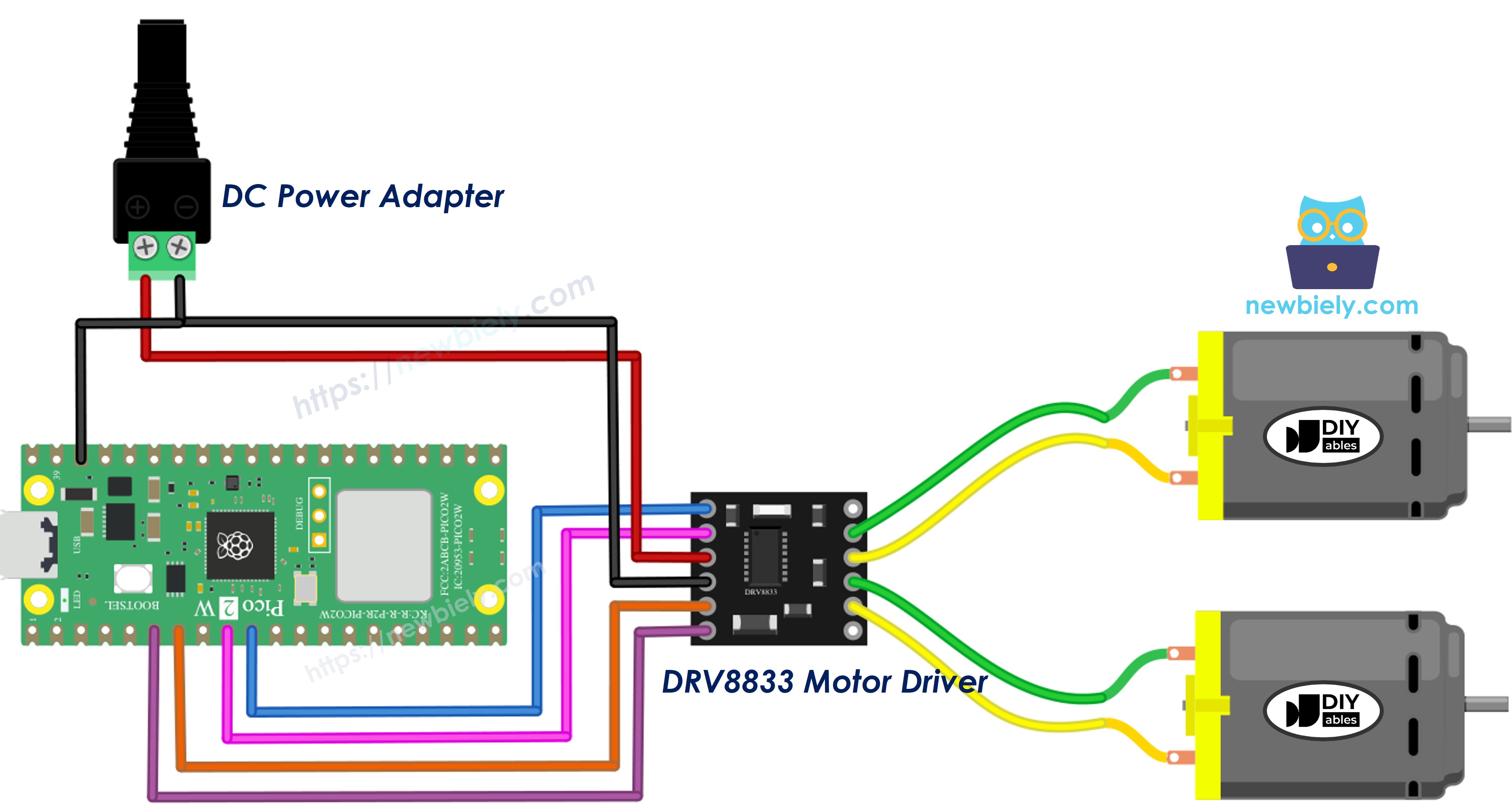
This image is created using Fritzing. Click to enlarge image
| DRV8833 Module | Raspberry Pi Pico / Other |
|---|---|
| IN1 | GP7 (pin 10) |
| IN2 | GP6 (pin 9) |
| IN3 | GP5 (pin 7) |
| IN4 | GP4 (pin 6) |
| EEP | 3V3(OUT) (pin 36) |
| GND | GND (pin 38) and the minus (-) of the DC power jack |
| VCC | the plus (+) of the DC power jack (5 volt adapter) |
| OUT1, OUT2 | motor A (left wheel) |
| OUT3, OUT4 | motor B (right wheel) |
Raspberry Pi Pico Code - Two DC Motors
This time a small drive() helper sets both wheels at once and prints the action name. The car moves forward, backward, turns left, turns right, and stops between each move.
Detailed Instructions
- Add the second motor and wires as shown in the diagram.
- Open the new code in Thonny and save it to the Pico as main.py (replace the old file).
- Plug in the 5 volt adapter, then click Run.
- If the car is on the table, lift its wheels off the surface first so it does not drive away.
- Look at the Shell and compare the messages with the wheels:
If one wheel turns the wrong way during "Car: forward", swap the two wires of that motor (OUT1/OUT2 for the left wheel, OUT3/OUT4 for the right wheel). You do not need to change the code.
When the script is saved as main.py in the root of the Raspberry Pi Pico, it starts by itself every time the Pico gets power. So you can unplug the USB cable, power the Pico from a battery, and the car will run on its own.