
ESP32 MicroPython IR Slotted Optical Speed Sensor
This tutorial instructs you how to use the IR slotted optical speed sensor with the ESP32 and MicroPython. In detail, we will learn:
- How the slot sensor knows if its gap is empty or blocked.
- How to connect the IR slot sensor to a ESP32 and place an encoder disc in its gap.
- How to write MicroPython code for the ESP32 to count objects and to measure the speed of a motor in RPM.
Hardware Preparation
Or you can buy the following kits:
| 1 | × | DIYables ESP32 Starter Kit (ESP32 included) | |
| 1 | × | DIYables ESP32 S3 Starter Kit (ESP32 S3 included) | |
| 1 | × | DIYables Sensor Kit (18 sensors/displays) |
Additionally, some of these links are for products from our own brand, DIYables .
Overview of IR Slotted Optical Speed Sensor
Look at the module from the side and you see the letter U. Between its two arms there is an open channel, and that channel is where the sensing happens. Makers know this part as an opto interrupter or a photo interrupter. Its output is digital, so MicroPython only has to read a 0 or a 1 from one pin.
| IR Slotted Optical Speed Sensor | |
|---|---|
| Sensor Type | slot-type photoelectric (IR LED + NPN phototransistor) |
| Slot Width | 5.9 mm |
| Operating Voltage | 3.3V to 5V DC |
| Output | digital (TTL) - LOW when blocked, HIGH when clear |
| Signal Conditioning | built-in Schmitt trigger |
| Mounting | M3 screw holes at both ends |
| Pins | 3 (VCC, GND, OUT) |
Where can you use it? Here are some ideas:
- Read the RPM of a motor with a slotted encoder disc
- Build a small tachometer
- Count pulses or items that pass through the gap
- Find the distance a robot has moved by counting wheel turns
- Give wheel speed feedback to a robot car
- Detect the end position (limit) of a moving part
Pinout
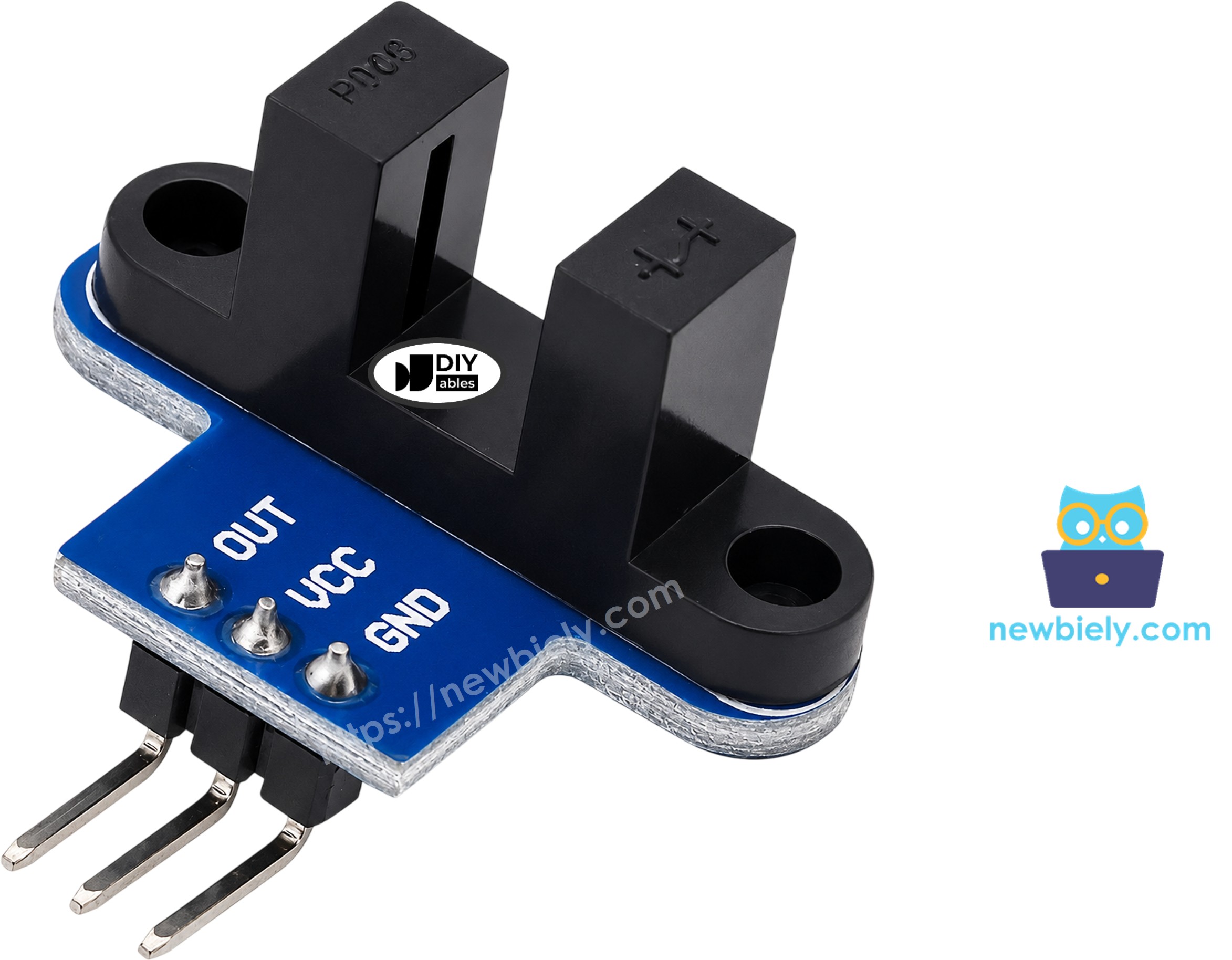
- VCC pin: connect to the 3.3V pin of the ESP32 (the module accepts 3.3 volts to 5 volts)
- GND pin: connect to GND (0 volts)
- OUT pin: connect to a GPIO of the ESP32, here GPIO18. It reads 0 when the channel is blocked and 1 when the channel is open
Different batches may put these three pins in a different order. Trust the labels on the board, not a picture.
A word about power: the voltage on OUT can climb as high as the voltage on VCC. The GPIO pins of the ESP32 work at 3.3 volts. If you feed the module 5 volts, OUT can push 5 volts into the GPIO. So take power from the 3.3V pin, and the signal stays safe.
How It Works

Inside the left arm sits an infrared LED. Inside the right arm sits an NPN phototransistor. They look straight at each other through the 5.9 mm channel.
- The channel is empty: the invisible beam hits the phototransistor. Pin.value() returns 1.
- A card, a finger or one tooth of an encoder disc is in the channel: the beam stops. Pin.value() returns 0.
The module also has a Schmitt trigger. It changes the slowly changing light level into a sharp 0 or 1. Because of this, the signal does not bounce, and your MicroPython script needs no debounce code.
Pick things that light cannot go through. A thin, see-through plastic sheet may let the IR beam pass, and then the sensor still reads "clear".
Not every brand uses the same logic. On some modules from other makers, the output is reversed. If yours reports a block while the channel is empty, swap the 0 and the 1 in the first script. The RPM script needs no change, because it counts one edge for every tooth either way.
Wiring Diagram
Wiring the ESP32 and the slot sensor
The module needs just three jumper wires. A breadboard is optional. You can also use a screw terminal block breakout board for the ESP32 if you want firm connections.
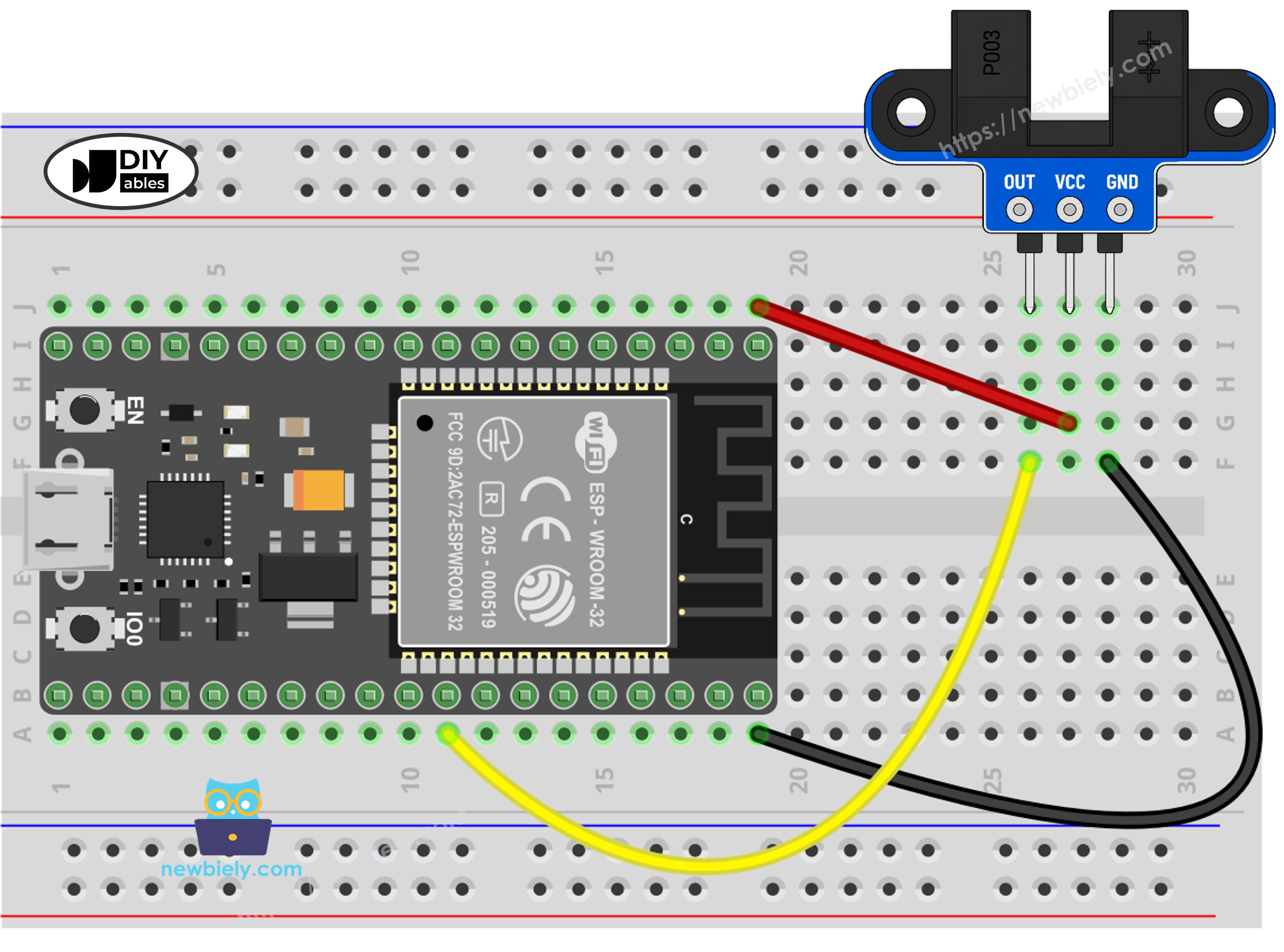
This image is created using Fritzing. Click to enlarge image
| Speed Sensor Pin | ESP32 Pin |
|---|---|
| VCC | 3.3V |
| GND | GND |
| OUT | GPIO18 |
Placing the encoder disc in the slot
For speed, you need a round disc with holes or teeth around its edge. When the disc turns, each tooth breaks the beam for a moment, and each break is one pulse. Press the disc onto the motor shaft or the wheel. Then screw the module down through its M3 holes, so the edge of the disc runs inside the channel. Turn the disc once by hand and check that it never rubs the sensor.
A slow spin with your finger is enough for a first try. If you want a motor to drive the disc, the motor has its own wiring. You can find it in the ESP32 MicroPython DC motor tutorial.
ESP32 MicroPython Code - Count Objects Passing Through the Slot
This first script polls GPIO18 in a fast loop. It keeps the last value it saw. When the new value is not the same, it prints one line. A change to 0 also adds one to the counter.
Detailed Instructions
Here's instructions on how to set up and run your MicroPython code on the ESP32 using Thonny IDE:
- Make sure Thonny IDE is installed on your computer.
- Confirm that MicroPython firmware is loaded on your ESP32 board.
- New to MicroPython on the ESP32? Start with the ESP32 MicroPython Getting Started guide.
- Connect the IR slotted optical speed sensor to the ESP32 board according to the provided diagram.
- Connect the ESP32 board to your computer with a USB cable.
- Open Thonny IDE on your computer.
- In Thonny IDE, go to Tools Options.
- On the Interpreter tab, pick MicroPython (ESP32) from the dropdown menu, and check that the right port is chosen (for example COM12 on Windows or /dev/ttyUSB0 on Linux).
- Copy the provided MicroPython code and paste it into Thonny's editor.
- Save the code to your ESP32 by:
- Clicking the Save button or pressing Ctrl+S.
- In the save dialog, choosing MicroPython device.
- Naming the file main.py.
- Click the green Run button (or press F5) to execute the script.
- Slide a strip of paper card into the gap, pull it out, and repeat two more times.
- Check out the message in the Shell at the bottom of Thonny.
If you name your script main.py and save it to the MicroPython device, it will run automatically every time the ESP32 is powered on.
ESP32 MicroPython Code - Read Motor Speed (RPM)
The second script turns the module into a tachometer. Polling is too slow when a disc spins fast, so this script uses an interrupt instead. The line sensor.irq(trigger=Pin.IRQ_FALLING, handler=count_pulse) tells the ESP32 to call count_pulse() at the exact moment the pin drops from 1 to 0. That drop happens once per tooth, so no tooth is counted twice.
The main loop sleeps for one second, copies the counter, and clears it. Then it does the math:
- One full turn of a 20-slot disc gives 20 pulses.
- Pulses in one second × 60 = pulses in one minute.
- Pulses in one minute ÷ 20 = turns per minute, which is the RPM.
Twenty slots is the usual count on the disc that comes with TT gear motors. Is your disc different? Set SLOTS_PER_TURN to the real number of slots.
Detailed Instructions
- Mount the disc and the module as in the encoder disc picture. Keep the same three wires.
- Copy the provided MicroPython code and paste it into Thonny's editor.
- Save it to the MicroPython device. Only one file can be called main.py. If you use that name again, this script replaces the first one. If you want to keep both, give this one another name, such as rpm.py.
- Click the green Run button (or press F5) to execute the script.
- Turn the disc with your hand, or switch on the motor.
- Check out the message in the Shell at the bottom of Thonny. In the sample below, the motor starts still, runs near 300 RPM, and then stops.
Only the file named main.py starts by itself at power on. So save the script you want to run on its own under that name, and keep the other one under a different name.
Want the distance too? One wheel turn moves the robot by the wheel circumference, which is π × wheel diameter. Multiply that by the number of turns.
Need to sense an object in front of the robot, not inside a narrow gap? Try the ESP32 MicroPython obstacle avoidance sensor tutorial.