
ESP32 MicroPython PC817 Optocoupler: Monitor 12V/24V DC Input Signal
Knowing whether a valve, a pump or a heater is actually running at this moment usually means reading the voltage on the line that feeds it - and that line is 12 or 24 volts, not 3.3. The ESP32 runs on 3.3 volts and is not 5V tolerant, so wiring such a line straight to one of its pins would destroy the board - a PC817 optocoupler isolation module solves that problem, and this guide shows you how to read one from MicroPython on the ESP32. We will cover the following details:
- How a PC817 optocoupler lets the ESP32 watch a 12V or 24V line without touching it electrically.
- Which of the three PC817 optocoupler modules - the 24V, the 12V or the 3-5V one - matches the line you want to watch, and what goes wrong if you buy the other one.
- How to wire the module to the ESP32, on a breadboard and on a screw terminal block.
- How to hang the module across a device that is already wired up, so the ESP32 can report whether that device is on or off.
- How to find out whether your module is active LOW or active HIGH, and how to flip the MicroPython code with a single constant.
- How to build the same input from the bare 4-pin PC817 chip, if you would rather fit the series resistor yourself.
Hardware Preparation
Or you can buy the following kits:
| 1 | × | DIYables ESP32 Starter Kit (ESP32 included) | |
| 1 | × | DIYables ESP32 S3 Starter Kit (ESP32 S3 included) | |
| 1 | × | DIYables Sensor Kit (18 sensors/displays) |
Additionally, some of these links are for products from our own brand, DIYables .
Buy one module: the right variant depends on the line you are watching, and the next section tells you which that is.
Overview of PC817 Optocoupler
The PC817 is a 4-pin chip that carries a digital signal across a gap using light instead of a wire. Inside it there is an infrared LED facing a phototransistor across an insulating gap. When current flows through the LED, its light switches the transistor on, so the signal crosses as light instead of electricity - which is why the two sides stay electrically separate. The PC817 is also sold under the names photocoupler, opto-isolator and optoisolator.
Most projects never touch the bare chip. What you actually buy is a PC817 optocoupler isolation module: the same chip on a small board, with the series resistor, a status LED and screw terminals already fitted, sold in 1, 2, 4 and 8 channel versions. That is what this tutorial wires up, and the bare chip waits at the end for anyone who would rather build it by hand.
Isolation is exactly what an ESP32 needs when the thing it has to watch is not a 3.3 volt sensor but an industrial or automotive line. Two jobs this tutorial is aimed at:
- Watching a 24 volt irrigation solenoid valve line, so the ESP32 knows which zone the irrigation controller has actually opened.
- Watching the 12 volt run signal of a standby generator or an inverter, so the ESP32 can log when the unit started and stopped.
Neither of those lines may ever meet the ESP32 directly. The PC817 sits in the middle and passes on nothing but light.
Which PC817 Optocoupler Module Do I Need?
Here is the thing the product photos never tell you: one module does not cover every input voltage. The resistor soldered onto the board is sized for one voltage, so the modules are sold as three separate variants and you buy the one that matches your signal.
| Line you want to watch | Module to buy | Where you meet that line |
|---|---|---|
| 24 volts DC | 24V module | Irrigation valves, PLC outputs, machine and truck wiring |
| 12 volts DC | 12V module | Generator and inverter run signals, alarm panels, automotive circuits |
| 3.3 or 5 volts DC | 3-5V module | The output of another board, or a low-voltage control board you want to keep at arm's length |
Get the variant wrong and one of two things happens:
- A 12V module fed from a 24 volt line sees roughly double the current its resistor was chosen for, and that extra current goes straight through the internal LED. The module will not last.
- A 24V module fed from a 12 volt line is the opposite problem: the LED is underdriven, so the output may switch late, switch only sometimes, or never switch at all. Nothing burns, but nothing works either.
※ NOTE THAT:
Picking the right variant is the module owner's version of sizing the series resistor - it is the one purchase decision on this page that actually matters. Once the correct module is on the bench there is no resistor to calculate and no maths to get wrong.
Pinout
A single-channel PC817 optocoupler isolation module has two screw terminals on the isolated field side and a three-pin header on the ESP32 side. A status LED beside the input terminals lights whenever the input side is energised, which is a useful thing to watch while you are testing.
- IN+ - the positive input terminal. Connect to the 24 volt valve line you want to watch.
- IN- - the negative input terminal. Connect to the ground of that same 24 volt circuit, NOT to the ESP32 ground.
- VCC - the supply for the output side. Connect to the ESP32 3V3 pin, which is 3.3 volts.
- GND - the ground of the output side. Connect to an ESP32 GND pin, which is 0 volts.
- OUT - the isolated output. Connect to an ESP32 input pin with its internal pull-up switched on, GPIO19 in this tutorial.
IN+ and IN- belong to the field side, VCC, GND and OUT belong to the ESP32 side, and nothing but the isolation gap inside the PC817 joins them.
Specifications
These are the numbers for the PC817 chip itself - the part sitting under the plastic on every one of the three module variants.
| Specification | Value |
|---|---|
| Package | 4-pin DIP |
| Input LED forward voltage (Vf) | about 1.2 V typical, 1.4 V max |
| Input LED forward current (If) | 20 mA continuous max, 5-20 mA normal range |
| Output voltage (VCEO) | 35 V max |
| Output current (IC) | 50 mA max |
| Collector power dissipation | 150 mW |
| Isolation voltage | 5000 Vrms for 1 minute |
| Current Transfer Ratio (CTR) | 50% to 600% depending on rank |
| Switching speed | rise time about 4 us, fall time about 3 us |
| Operating temperature | -30 C to +100 C |
The 5000 Vrms isolation figure is the number that matters here. It is the reason a spike on the 24 volt side has no path into the ESP32.
Why the Reading Is Inverted
The output side of the PC817 does not produce a voltage of its own. All it can do is connect the ESP32 pin to GND or leave it alone, so the pin needs a pull-up to have a defined level when the transistor is off. On the ESP32 the internal pull-up is the easiest choice, and a 10 kohm resistor from the pin to 3.3 volts does the same job.
With the pull-up in place:
- 12V/24V signal PRESENT: the LED lights, the phototransistor conducts, and the ESP32 pin is dragged down, so it reads LOW.
- 12V/24V signal ABSENT: the LED is dark, the phototransistor is off, and the pull-up wins, so the ESP32 pin reads HIGH.
So the reading is upside down compared to what you might expect, and the MicroPython code has to flip it back. This is the same active-LOW habit you meet in the ESP32 MicroPython Button and ESP32 MicroPython Limit Switch tutorials.
One more thing about the ESP32 in particular: pick a normal GPIO for this project. GPIO34 to GPIO39 are input-only pins and they have no internal pull-up at all, so the module output would float on them. This tutorial uses GPIO19.
Is Your Module Active LOW or Active HIGH?
Everything above is settled physics for the bare chip. A module is a different matter, because some manufacturers add an inverting stage on the board so that OUT follows the input instead of opposing it. Both kinds are on sale, they look alike in the photos, and the listing rarely says which one you are getting. So do not assume - spend a minute and measure it.
- Wire the module to the ESP32 as shown below, but leave IN+ and IN- disconnected for now.
- Open the script below in Thonny and press the green Run button. It prints the raw level of GPIO19 in brackets at the end of every line.
- Watch the Shell at the bottom of the Thonny window and note the number that appears while there is no signal on the input.
- Now apply the signal to IN+ and IN-. The status LED on the module should light.
- Note the number the Shell prints while the signal is present. That number is your module's active level: 0 means active LOW, 1 means active HIGH.
The status LED is the cross-check. It is wired to the input side, so it lights exactly when the field signal is there - if the LED is on and the Shell is still reporting the line as OFF, polarity is the thing to fix, not the wiring.
Then fix it in one place. The script has a single constant near the top, MODULE_ACTIVE_LOW, which ships as True because that is how most modules behave. If your test says the active level is 1, set it to False and everything downstream comes out the right way round. Nothing else in the script needs touching.
Keep the Two Grounds Apart
This is the whole point of the exercise, so it is worth saying plainly: do NOT connect the ground of the 12V/24V circuit to the GND pin of the ESP32. The 12 volt or 24 volt supply keeps its own ground, the ESP32 keeps its own ground, and the two never meet. If you tie them together the module will still switch and the code will still work, but the isolation is gone and the ESP32 is once again exposed to whatever happens on the high side.
Wiring Diagram
Wiring the PC817 Optocoupler Isolation Module
With the right variant in hand there is nothing to calculate. The 24 volt valve line goes to IN+, the ground of that same 24 volt supply goes to IN-, and that ground stays on the module and never reaches the ESP32. On the other side of the isolation gap, VCC, GND and OUT go to the ESP32.
- This is how to connect the ESP32 and the PC817 optocoupler isolation module using a breadboard. Feed the module VCC from the ESP32 3V3 pin, which supplies 3.3 volts, because the ESP32 is a 3.3 volt board and is not 5V tolerant.
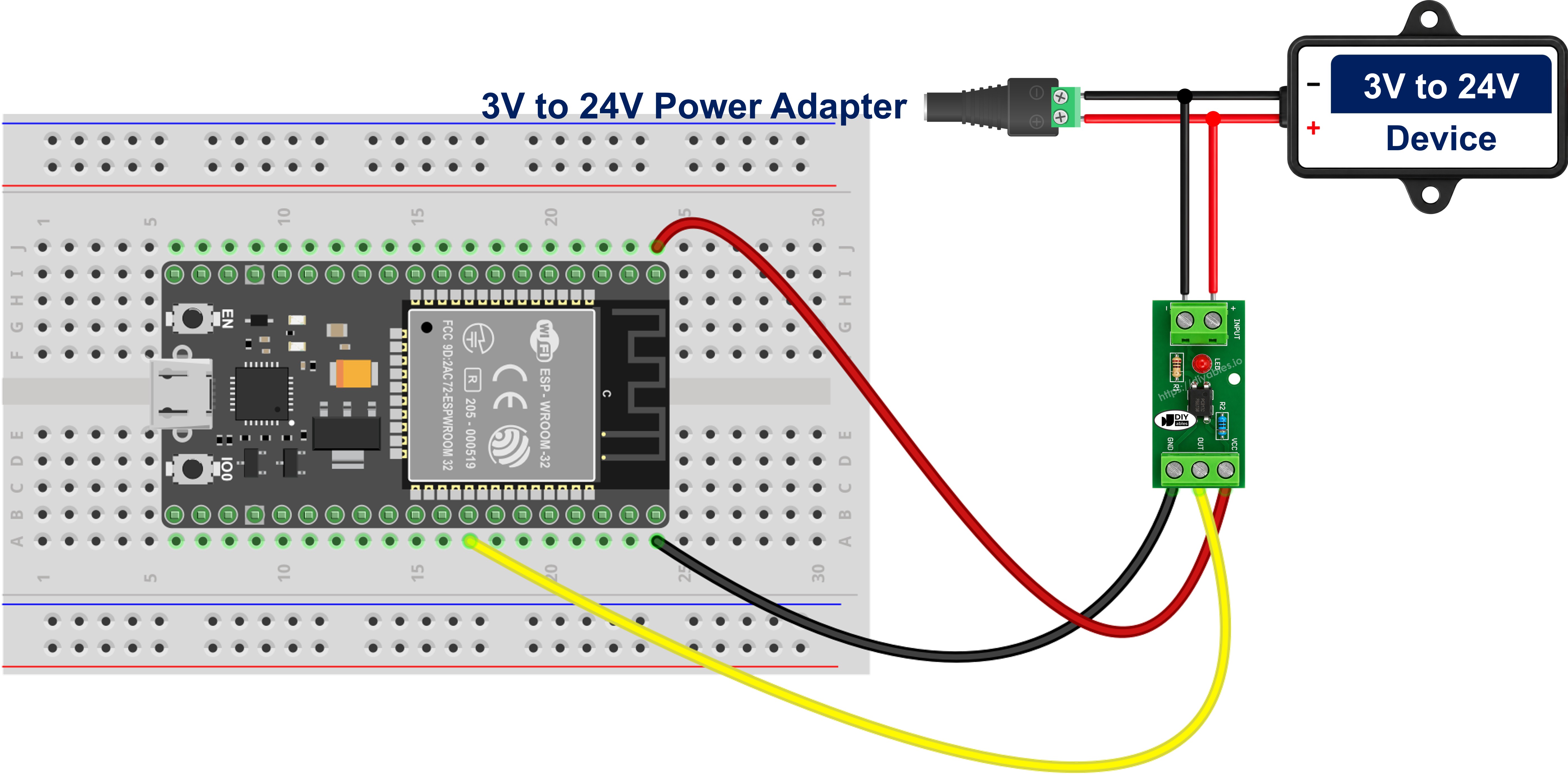
This image is created using Fritzing. Click to enlarge image
- This is how to connect the ESP32 and the PC817 optocoupler isolation module using a screw terminal block breakout board, which is the tidier choice once the 24 volt field wiring is real cable rather than jumper wires.
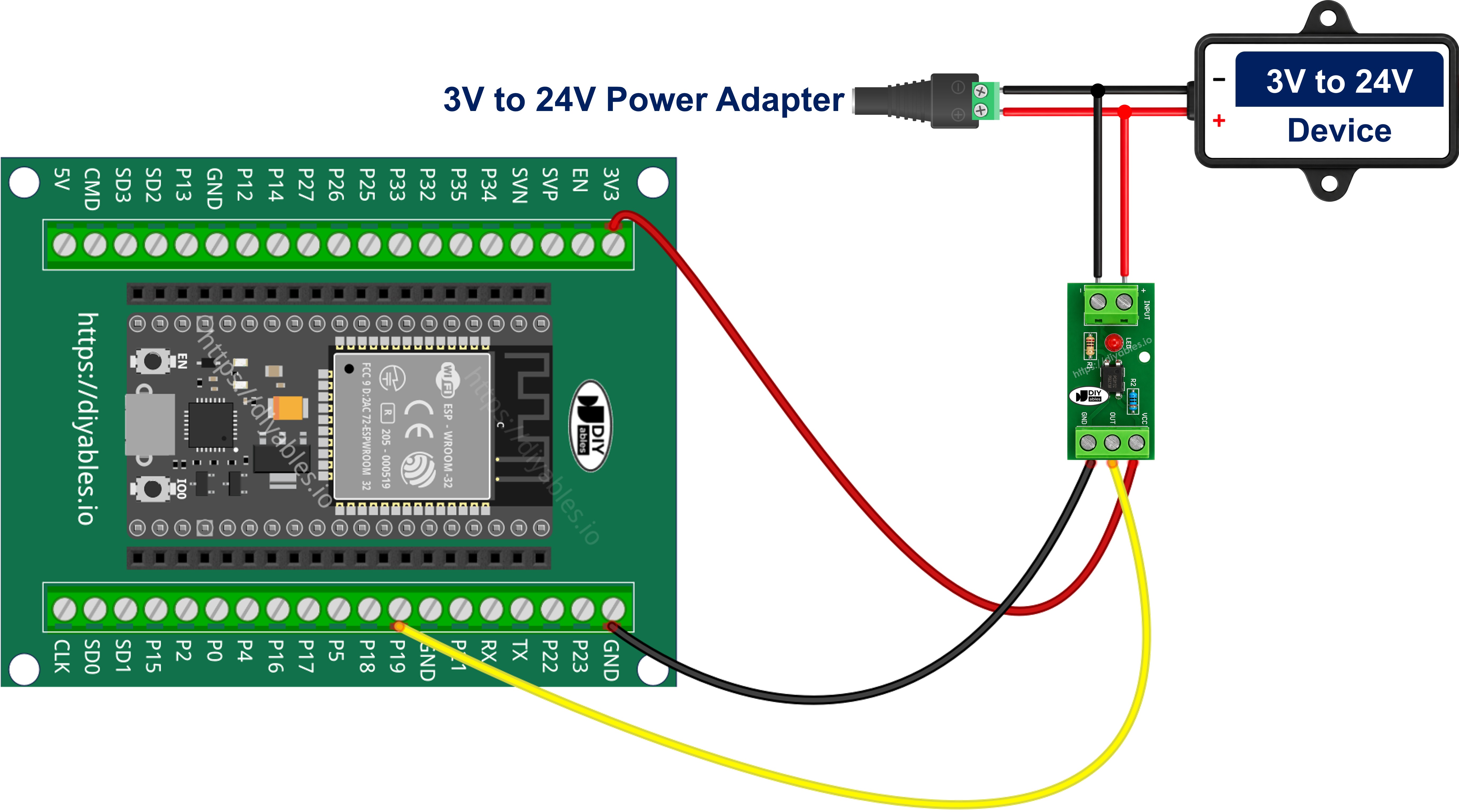
If your module has more than one channel, each channel gets its own pair of input terminals and its own OUT pin, and every channel on the board is built for the same input voltage.
Wiring the PC817 Module in Parallel to Monitor a Device On or Off
The wiring above assumes you have a signal wire waiting for you. Most of the time you do not - what you have is a device that is already installed and already working, and the thing you want to know is whether it is running at this second. The answer is to hang the module input across that device, in parallel with it, and leave every existing wire where it is.
Take the 24 volt irrigation solenoid valve this tutorial keeps coming back to. The irrigation controller feeds the valve coil through its own cable and you cut none of it. You only add two wires, and both land on the screw terminals of a 24V module:
- From the switched terminal of the valve coil to IN+.
- From the return terminal of the same coil to IN-.
There is no resistor to add here - the module already carries the one that suits 24 volts, which is exactly why the variant had to be right. The tap draws about 10 mA. Beside what a solenoid coil pulls that is nothing, so the valve keeps opening and closing exactly as it always did. This is a read-only measurement bolted onto a live circuit.
WARNING
Never wire the module in series with the valve. In series the whole coil current has to pass through the tiny internal LED, and the chip is destroyed the instant the controller energises the zone. The optocoupler input goes across the device, never in line with it.
Two more things to get right on the input side. Polarity first: IN+ and IN- feed an LED and it conducts one way only, so swapping them does not damage anything but the input will simply never switch on - work out which side of the tap is positive before you strip a wire. Second, the coil is inductive, and a solenoid, relay, contactor or motor throws a big reverse spike the moment it is switched off. The PC817 input LED is rated for only 6 V in reverse, so that spike can kill it. Fit an ordinary diode in reverse-parallel directly across the two input terminals - diode cathode to IN+, diode anode to IN-. In normal running it is reverse-biased and does nothing at all; on a spike it conducts and clamps the reverse voltage to well under a volt. A 1N4148 covers a small tap like this one, a 1N4007 a heavier one.
A false reading is also possible in the other direction. Some PLC transistor outputs, triac outputs and LED-lamp drivers leak a little current even when they are switched off, and enough leakage keeps the internal LED faintly lit, so the ESP32 goes on reporting the valve as energised when the controller has already closed it. The symptom is a reading that never returns to inactive. Fit a bleeder resistor of about 4.7 kohm to 10 kohm across IN+ and IN- and the leakage runs through that instead of the LED. And one limit worth knowing before you start: the PC817 input is a single LED, so it responds to one polarity only and is the wrong part for sensing an AC line, which needs an optocoupler whose input stage carries two back-to-back LEDs.
Because the tap sits across the device rather than across the controller's command, what the ESP32 reads is the device's real state - including the times something else energised the zone, and the times the controller called for it and nothing came on. That is what turns the script into a run-hour counter for each valve, a "did the pump actually start?" alert, or an idle-time log for a machine. Be honest about what it proves, though: it tells you the device is energised, not that it is working, and a seized motor or a burnt-out heater element still draws power and still reads as ON.
Optional: Build It from the Bare PC817 Chip
Prefer to solder your own? The raw 4-pin PC817 does the same job once you fit the series resistor, which is worth doing when the input voltage is fixed. A dot or a notch marks pin 1 and the numbering runs anticlockwise: pin 1 anode and pin 2 cathode of the LED on the field side, pin 3 emitter and pin 4 collector of the phototransistor on the ESP32 side.
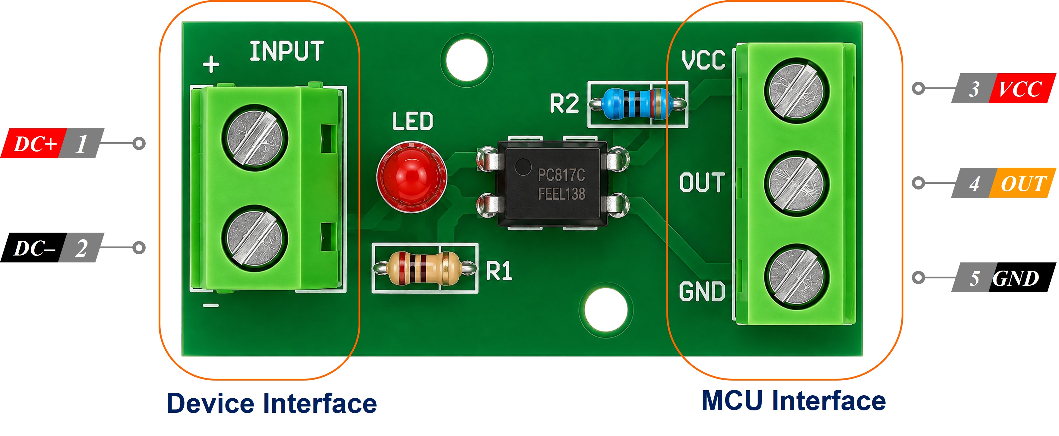
Size the resistor with R = (Vin - 1.2) / 0.01 for about 10 mA: 220 ohm at 3.3 volts, 390 ohm at 5 volts, 1 kohm at 12 volts, and 2.2 kohm at 24 volts in a 1/2 W part. Leave a 1 kohm in place on a 24 volt line and about 22.8 mA flows, past the 20 mA limit of the chip.
Then wire the resistor between the signal and pin 1, pin 2 to the ground of that external circuit, pin 3 to an ESP32 GND pin, which is 0 volts, and pin 4 to GPIO19. The code below runs unchanged.
ESP32 MicroPython Code - PC817 Optocoupler
No library is needed. Reading a PC817 module is ordinary digital input work, so a Pin object with Pin.PULL_UP is the entire driver. The script below watches the isolated input and prints a line only when it changes state, which keeps the Thonny Shell readable when the valve stays open for a while. Each line ends with the raw level of GPIO19, which is what makes the polarity test above possible.
Detailed Instructions
Here's instructions on how to set up and run your MicroPython code on the ESP32 using Thonny IDE:
- Wire the module to the ESP32 as shown in the module wiring diagram above, and double-check that the 12V/24V ground is nowhere near the ESP32 GND before you power anything up.
- Make sure Thonny IDE is installed on your computer.
- Confirm that MicroPython firmware is loaded on your ESP32 board.
- If this is your first time using an ESP32 with MicroPython, check out the ESP32 MicroPython Getting Started guide for step-by-step instructions.
- Connect the ESP32 board to your computer with a USB cable.
- Open Thonny IDE on your computer.
- In Thonny IDE, go to Tools Options.
- Under the Interpreter tab, choose MicroPython (ESP32) from the dropdown menu.
- Make sure the correct port is selected. Thonny IDE usually detects it automatically, but you might need to select it manually (like COM12 on Windows or /dev/ttyACM0 on Linux).
- Copy the provided MicroPython code and paste it into Thonny's editor.
- Save the code to your ESP32 by:
- Clicking the Save button or pressing Ctrl+S.
- In the save dialog, choose MicroPython device.
- Name the file main.py.
- Click the green Run button (or press F5) to execute the script.
- Switch the 24 volt valve line on, leave it on for a few seconds, then switch it off again.
- Check out the message in the Shell at the bottom of Thonny.
If the Shell reports the opposite of what the module status LED is doing, that is the active-HIGH case from earlier - set MODULE_ACTIVE_LOW to False and run the script again.
Because the script was saved to the MicroPython device under the name main.py, it starts by itself every time the ESP32 is powered on, with no computer attached. That is what turns this into a standalone isolated input monitor - pair it with the ESP32 MicroPython Relay tutorial and the ESP32 can react to the 24 volt line instead of only reporting it.