
Arduino MKR WiFi 1010 - PC817 Optocoupler: Monitor 12V/24V DC Input Signal
The Arduino MKR WiFi 1010 is a 3.3V board, and its GPIO pins are not 5V tolerant - touching one with 12V or 24V destroys it instantly. A PC817 optocoupler module solves that problem completely: it carries the signal across an insulating gap as light, so the Arduino MKR WiFi 1010 learns whether an external 12V or 24V line is energised without ever being wired to it. This tutorial shows you how to turn a PC817 module into a safe isolated digital input on the Arduino MKR WiFi 1010, which of the three module variants to buy for the signal you want to watch, and how to find out which way round your module's output reads. Along the way it answers the question that actually sends people hunting for an optocoupler in the first place: *is that machine, pump or lamp really switched on right now?*
What You'll Learn:
- Why the 3.3V Arduino MKR WiFi 1010 needs a PC817 optocoupler before it can touch a 12V or 24V circuit
- Which of the three module variants - 3-5V, 12V or 24V - matches the signal you want to watch
- What actually goes wrong when a module is fed from the wrong voltage
- How to wire a PC817 optocoupler module to the Arduino MKR WiFi 1010's D18 pin and 3.3V rail
- How to find out in under a minute whether your module reads active-LOW or active-HIGH, and flip it with one constant
- How to tap the module across a device, in parallel, to monitor whether it is on or off
- How to read a 24V PLC output safely with the Arduino MKR WiFi 1010
- Why the 12V/24V ground must never be joined to Arduino MKR WiFi 1010 GND
- How to build the same isolated input from a bare 4-pin PC817 chip, if you would rather
Real-World Applications:
- Remote machine status: the Arduino MKR WiFi 1010 watches a 24V machine "running" or "fault" lamp line and reports it over its WiFi link
- Off-site battery and charger monitoring: check whether a 12V solar charger or battery-charging circuit at a remote cabin is actually live
- Run-hour and "did it start?" logging: keep a count of how long a 12V pump or heater is actually switched on each day, and push an alert over WiFi when it fails to come on at all
- Industrial signal reading: bring a 24V PLC output into a 3.3V microcontroller without a level shifter
- Long cable runs: read a 24V switch at the far end of a long wire where a bare signal wire would pick up noise
- Contactor and solenoid sensing: detect when a 12V or 24V coil is energised
- Alarm panel tie-in: monitor a 12V alarm or garage-door controller output without loading it
Hardware Preparation
| 1 | × | Arduino MKR WiFi 1010 | |
| 1 | × | Micro USB Cable | |
| 1 | × | Optocoupler Module 12V | |
| 1 | × | Optocoupler Module 3-5V | |
| 1 | × | Breadboard | |
| 1 | × | Jumper Wires |
Or you can buy the following kits:
| 1 | × | DIYables Sensor Kit (18 sensors/displays) |
Additionally, some of these links are for products from our own brand, DIYables .
You need one optocoupler module - pick the variant that matches your signal, and the next section shows how to choose.
Overview of PC817 Optocoupler
The PC817 - also sold as a photocoupler, opto-isolator or optoisolator - is a 4-pin DIP chip that passes a digital signal between two circuits that share no wires at all. Inside it there is an infrared LED facing a phototransistor across an insulating gap. When current flows through the LED, its light switches the transistor on, so the signal crosses as light instead of electricity. That is exactly why the two sides stay electrically separate, and why the PC817 is rated for 5000 Vrms of isolation for one minute.
A PC817 optocoupler module is that chip already mounted on a small board, with its series resistor fitted, screw terminals on the isolated side, a pin header on the Arduino MKR WiFi 1010 side and usually a status LED. Modules are sold in 1, 2, 4 and 8 channel versions. Everything below assumes a module unless it says otherwise.
The handful of PC817 numbers worth knowing:
| Parameter | PC817 |
|---|---|
| Package | 4-pin DIP |
| LED forward voltage (Vf) | about 1.2 V typical, 1.4 V max |
| LED forward current (If) | 20 mA continuous max, 5-20 mA normal, 10 mA a good target |
| Output voltage (VCEO) | 35 V max |
| Output current (IC) | 50 mA max |
| Collector power dissipation | 150 mW |
| Isolation voltage | 5000 Vrms for 1 minute |
| Current Transfer Ratio (CTR) | 50% to 600% depending on rank |
| Switching speed | about 4 us rise, 3 us fall |
| Operating temperature | -30 C to +100 C |
Which Optocoupler Module Do I Need?
The resistor that limits current through the internal LED is already soldered onto the module, and it is sized for one input voltage. That is why these boards are not sold as a single universal part: there are three variants, and the one you buy has to match the signal you intend to watch. Choosing the variant is the module equivalent of sizing the resistor - get it right at the checkout and there is nothing left to calculate.
| Signal you want to watch | Module variant to buy |
|---|---|
| 24V PLC output, industrial sensor, 24V contactor coil | 24V module |
| 12V solar charge controller output, 12V pump, alarm panel, vehicle circuit | 12V module |
| 5V or 3.3V logic from a separate board or the far end of a long cable | 3-5V module |
What happens when the variant is wrong:
- A 12V module fed from a 24V line sees roughly double the current its resistor was chosen for, and all of it goes through the internal LED. That damages the module.
- A 24V module fed from a 12V line underdrives the LED instead. Nothing burns, but the output may switch late, switch unreliably, or never switch at all - which looks like a dead circuit rather than an obvious mistake.
- Multi-channel modules carry the same variant voltage on every channel. An 8-channel 24V board is eight 24V inputs, not a mixture.
The 3-5V variant is not padding, by the way. Isolating a 5V or 3.3V logic signal is worth doing whenever the two circuits run from separate supplies, sit at opposite ends of a long cable, or one of them is electrically noisy - a motor driver, say, or the low-voltage control board buried inside a mains-powered appliance. Isolation is about breaking the ground path, not only about taming a high voltage.
Why This Matters On A 3.3V Arduino MKR WiFi 1010
Boards such as the classic Uno run at 5V, so people sometimes get away with sloppy input circuits. The Arduino MKR WiFi 1010 is different: it is a 3.3V board and its GPIO pins are not 5V tolerant. Anything above roughly 3.3V on a digital pin damages the microcontroller.
This is where the PC817 really earns its place on this board. The output side of the module is powered from the Arduino MKR WiFi 1010's own 3.3V rail. All the phototransistor ever does is pull the digital pin down to GND. It cannot push voltage into the pin, because the pin's only source of voltage is the board's own pull-up. That means:
- The digital pin never sees more than 3.3V, no matter whether the isolated side is running at 12V or 24V.
- Nothing about the external voltage changes the output wiring - a 24V line and a 12V line look identical to the Arduino MKR WiFi 1010.
- You do not need a level shifter, a divider, or a 5V tolerant buffer.
Keep the module's two sides apart in your head. The variant you bought - 3-5V, 12V or 24V - describes the input side and nothing else: it says what voltage may arrive at the IN+ and IN- terminals. It makes no statement at all about the output side. Whichever variant is on your desk, its VCC pin is fed from this board's 3.3V pin, never from the monitored circuit. A 24V module does not want 24V on VCC; the 24V belongs on IN+, and it stops there, on the far side of the insulating gap. Blurring those two facts together is how a 3.3V board ends up with 24V on a pin header.
If you would rather read an external voltage as a *number* than as an on/off state, see the Arduino MKR WiFi 1010 - Measure Voltage tutorial instead. The PC817 answers a different question: "is the line live, yes or no?"
Optocoupler Module Active-HIGH Or Active-LOW?
With a bare PC817 wired the way this page describes, the answer is settled physics. The Arduino MKR WiFi 1010 digital pin is held HIGH by a pull-up (the internal one is ideal - it pulls to 3.3V), and the phototransistor's only job is to drag that pin down to GND, so the logic comes out backwards:
| External 12V/24V signal | PC817 LED | Phototransistor | Arduino MKR WiFi 1010 pin reads |
|---|---|---|---|
| PRESENT | on | conducting | LOW |
| ABSENT | off | not conducting | HIGH |
With a module, do not assume it. Some manufacturers add an inverting stage on the board so the output follows the input instead, and both kinds are sold side by side, often under near-identical photographs. Yours is whatever it is, so spend a minute finding out:
- Wire the module as shown below, upload the sketch from this page and open the Serial Monitor.
- Leave the input terminals with no signal on them, and note which word is printing - LIVE or idle.
- Now apply the monitored signal to IN+ / IN-, and note which word prints.
- Whatever prints while the signal is present is your module's active level. The sketch ships assuming active-LOW, so if it says LIVE with nothing connected and idle once the signal arrives, yours is the active-HIGH kind.
- Cross-check against the module's own status LED: that LED lights when the input side is energised. If the LED is lit while the sketch still says idle, the pin and the LED disagree, and that is exactly the case the next line fixes.
One edit corrects it. In the sketch below, change:
to false, upload again, and every reading flips with it - nothing else in the sketch needs touching. Once that constant is right, signalActive is true when the external line is live and the rest of your code can forget the whole question, the same way you already handle inverted logic in the Arduino MKR WiFi 1010 - Button and Arduino MKR WiFi 1010 - Limit Switch tutorials.
※ NOTE THAT:
The isolation rule - the whole point of this circuit
Do NOT connect the ground of the 12V/24V circuit to the Arduino MKR WiFi 1010's GND. The two grounds must stay separate. That separation is what protects the board. If you tie the grounds together, the PC817 still switches and the sketch still works, so the mistake is easy to miss - but the isolation is gone, and a fault on the 12V/24V side now has a path straight into your Arduino MKR WiFi 1010.
Wiring Diagram
Wiring The Optocoupler Module
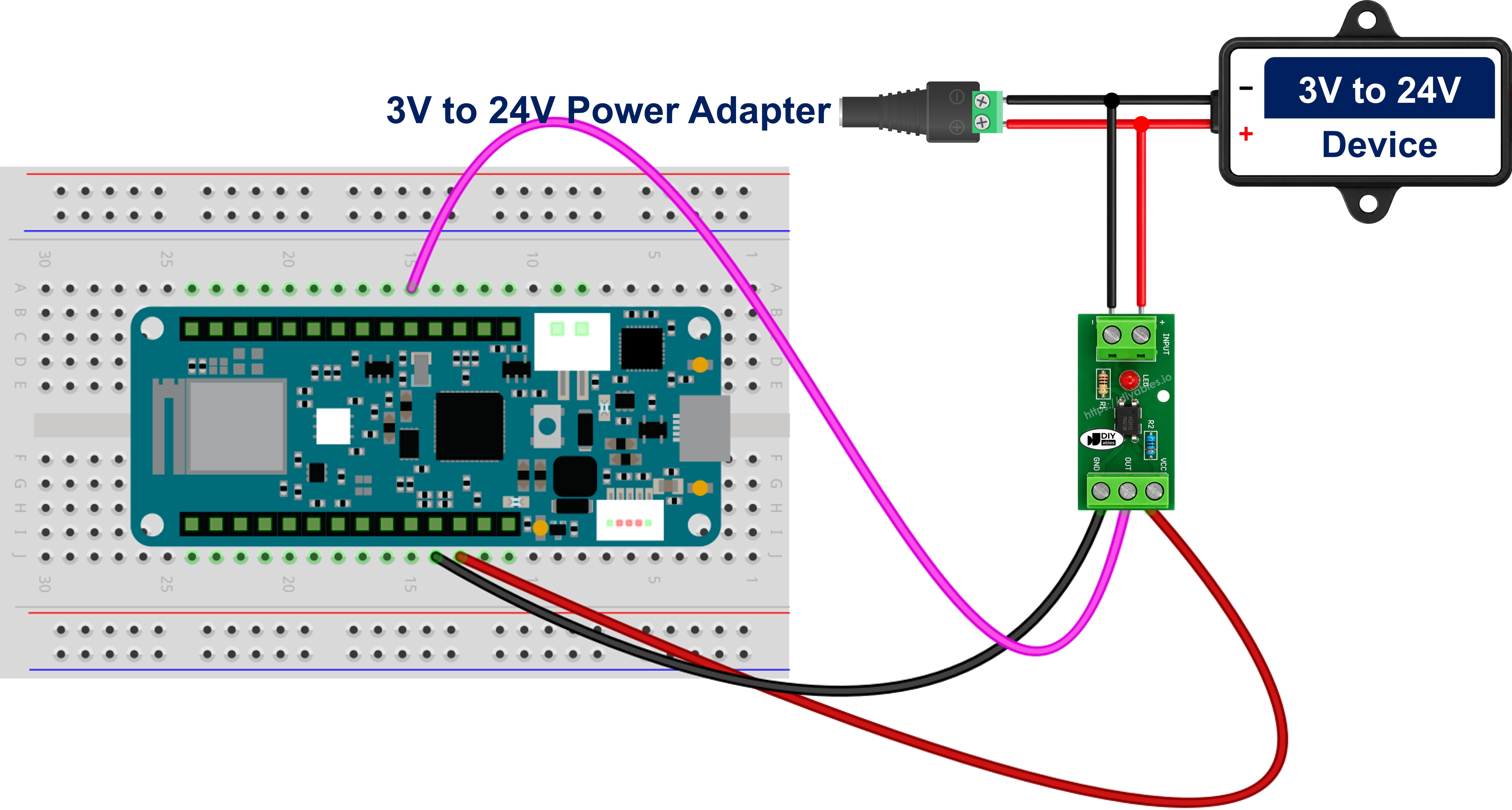
This image is created using Fritzing. Click to enlarge image
The module splits cleanly in two, and so does the wiring. On the isolated side, the monitored signal goes to the IN+ screw terminal and that circuit's own ground goes to IN- - that is the whole job, because the series resistor is already on the board, which is precisely why the variant had to match this voltage. On the Arduino MKR WiFi 1010 side, VCC goes to the board's 3.3V pin, GND to board GND, and OUT to digital pin D18.
Leave the internal pull-up enabled on D18 in software. Most of these modules present an open-collector output, and the pull-up is what gives the idle state a defined level to sit at.
※ NOTE THAT:
Powering the module's VCC from the Arduino MKR WiFi 1010's 3.3V pin is deliberate. The output transistor can then only ever swing between 0V and 3.3V, which keeps it inside what this board's non-5V-tolerant pins accept. That is just as true of a 24V module as of a 3-5V one - the variant changes the input side, not this.
Tapping The Module In Parallel With The Device You Want To Monitor
The diagram above shows where the module sits on the Arduino MKR WiFi 1010 side. What it does not show is where the other end lands on the equipment you are watching - and that is where the one genuinely destructive mistake hides.
The module's input goes across the device, in parallel with it - never in series with it. Wired in series, the device's entire load current would have to squeeze through that tiny internal LED, and the module would be gone the moment the load switched on. The input side is a tap, not a switch in the load path.
Take the load output of a 12V solar charge controller at an unattended off-grid site as the worked example. With a 12V module, the controller's switched load terminal goes to IN+ and that circuit's own negative return goes to IN-. There is no series resistor to add here - the module already carries the one its variant needs. Nothing is cut and nothing is rerouted, so whatever hangs off that output keeps running exactly as before; the tap draws only a few milliamps, which is nothing next to what a lamp, pump or valve on the same terminal pulls. It is a read-only measurement.
Two things to get right before you power it up:
- Polarity matters. Behind the terminals sit the anode and cathode of an LED, so the tap conducts in one direction only. Swap IN+ and IN- and the input simply never lights - no damage, but no reading either, and the status LED stays dark to tell you so. Work out which side of the tap is positive first.
- The reading follows the device, not your sketch. Because the tap sits across the load, it reports what that output is really doing - including the evening the charge controller switches it on by itself, and including the morning it should have come on and did not. That is what turns this circuit into run-time logging, idle-time counting and "did it actually start?" alerts pushed home over the board's WiFi link.
One honest limitation: this tells you the device is energised, not that it is functioning - a seized pump or a burnt-out heating element still draws power and still reads as ON.
※ NOTE THAT:
Inductive loads need a clamp diode across the tap
If the thing on the far end of the tap is a relay coil, contactor, solenoid valve or motor, it throws a large reverse-voltage spike every time it switches off, and the PC817's input LED is rated for only 6 V in reverse. Fit an ordinary diode in reverse-parallel directly across the module's input terminals - diode cathode to IN+, diode anode to IN- (on a bare chip, cathode to pin 1 and anode to pin 2). In normal operation it is reverse-biased and does nothing at all; on a spike it conducts and clamps the reverse voltage to well under a volt. A 1N4148 covers small taps, a 1N4007 heavier ones.
Leaky solid-state outputs cause false readings. Some PLC transistor outputs, triac outputs and LED-lamp drivers pass a small current even when they are switched off. Enough of that leakage partially lights the module's internal LED, and the Arduino MKR WiFi 1010 then reports the device as ON while it is sitting there off; the giveaway is a reading that never drops back to inactive, usually with the status LED glowing faintly. The cure is a bleeder resistor of about 4.7 kohm to 10 kohm fitted in parallel with the module's input terminals, so the leakage drains through it instead of through the LED.
Finally, keep this to DC. The PC817's input is a single LED and responds to one polarity only, so it is the wrong part for sensing an AC line - that job needs an optocoupler whose input stage carries two back-to-back LEDs.
Prefer To Build It From The Raw Chip?
Solder a bare PC817 instead, and you take on the job the module's variant did for you: picking the series resistor.
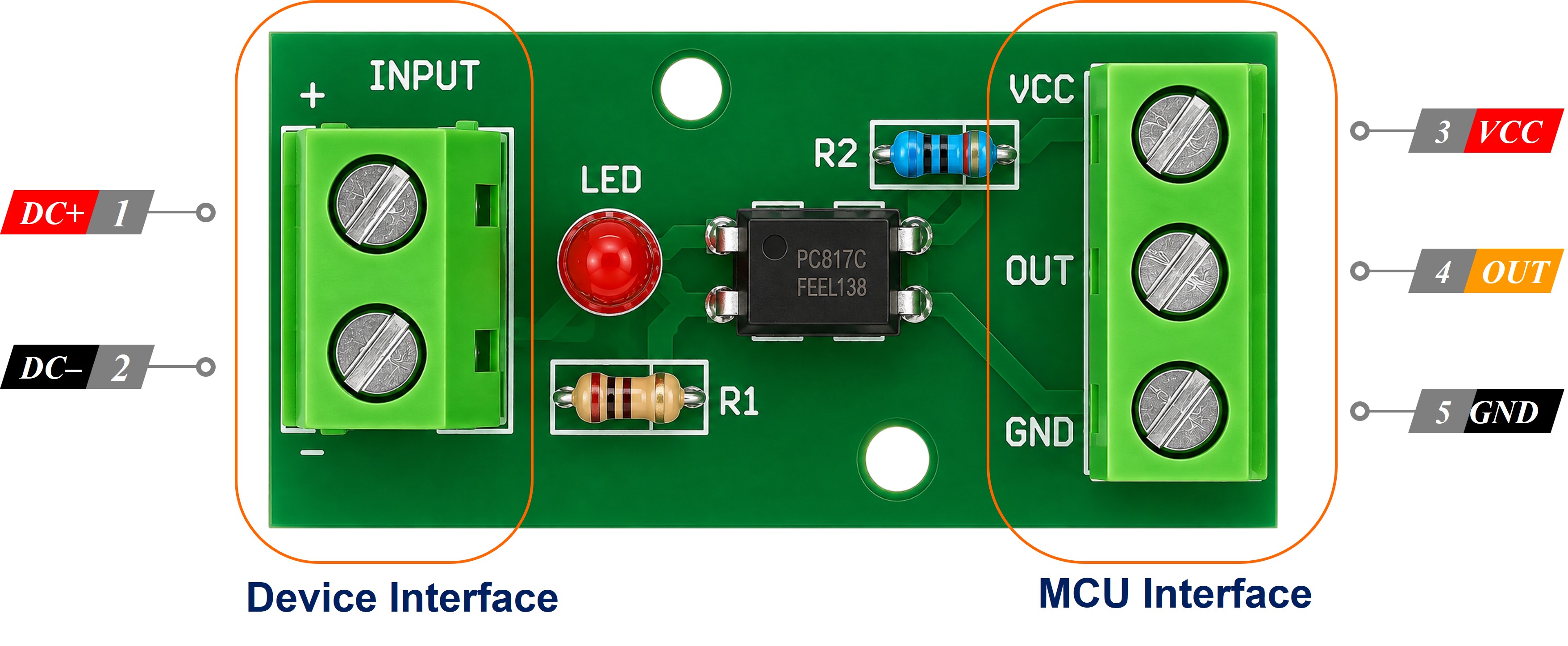
Pin 1 is marked with a dot or a notch. Pin 1 - Anode and Pin 2 - Cathode are the input LED: the external positive arrives at pin 1 through your resistor, and that circuit's ground goes to pin 2 and nowhere else. Pin 4 - Collector goes to digital pin D18, and Pin 3 - Emitter goes to the board's GND.
Size the resistor with R = (Vin - 1.2) / 0.01, aiming for about 10 mA through the LED, which gives 3.3V: 220 ohm, 5V: 390 ohm, 12V: 1 kohm, 24V: 2.2 kohm (use a 1/2 W part at 24V). Change the input voltage and you change the resistor: leaving 1 kohm fitted when a tap moves from 12V to 24V pushes about 22.8 mA through a 20 mA LED. Wired this way the reading is always inverted, so leave MODULE_ACTIVE_LOW set to true.
How To Program For PC817
The PC817 needs no library at all - this is plain digital input reading. Three steps cover the whole job.
- Configure the pin as an input with the internal pull-up turned on, so it idles HIGH at 3.3V:
- Read the pin and turn it into a plain "is the line live?" boolean, letting the polarity constant do the thinking so the same sketch suits either kind of module:
- Act on the value, or compare it with the previous value to catch the moment the external line switches:
Once signalActive is a clean boolean, it is also the value you would go on to publish over the board's WiFi link - see the Arduino MKR WiFi 1010 - Web Server tutorial for that step. The sketch below stays focused on the isolated reading itself.
Arduino MKR WiFi 1010 Code - PC817 Optocoupler
Detailed Instructions
New to Arduino MKR WiFi 1010? Complete our Getting Started with Arduino MKR WiFi 1010 tutorial first to set up your development environment.
- Check that your module's variant matches the signal you are about to watch: 3-5V, 12V or 24V
- Build the circuit shown in the module wiring diagram above, keeping the 12V/24V ground away from the board's GND
- Plug your Arduino MKR WiFi 1010 into your computer's USB port
- Launch the Arduino IDE and select the Arduino MKR WiFi 1010 board and its COM port
- Copy the code above and paste it into the Arduino IDE
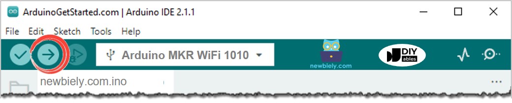
- Click the Upload button to compile the sketch and send it to your board
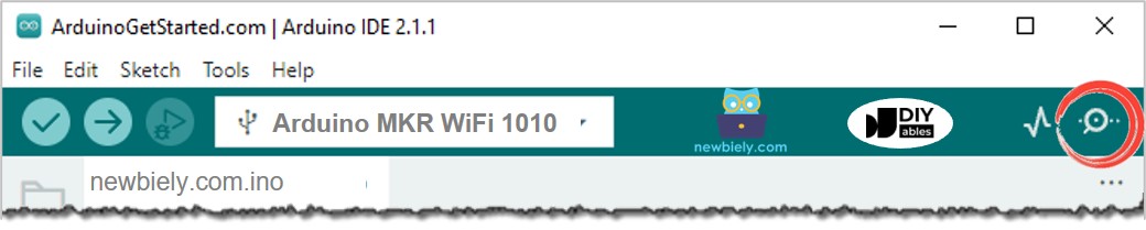
- Open the Serial Monitor in the Arduino IDE
- Switch the external 12V or 24V line on and off a few times
- Watch the Serial Monitor - the output should look like this
If the two words are swapped - "LIVE" while the external line is actually off - your module is one of the active-HIGH ones: set MODULE_ACTIVE_LOW to false and upload again. On a bare-chip build the same symptom usually means the phototransistor's emitter and collector are the wrong way round, so swap PC817 pins 3 and 4.
Challenge Yourself
Once the basic isolated input works, try extending it:
- Easy: light the Arduino MKR WiFi 1010's built-in LED whenever the isolated line is live, so you can see the state without the Serial Monitor
- Easy: rename the printed labels to match your own equipment, for example "Pump contactor: ENERGISED"
- Medium: count how many times the 24V line switches on during a shift, and print a running total
- Medium: use millis() to measure how long the external line stays energised each time
- Medium: turn the sketch into a run-hour meter for the monitored device, adding up its total ON time and printing the tally once an hour
- Medium: raise an "it never started" warning if the monitored output has not gone live within the window you expect
- Advanced: add software debouncing so a chattering contactor does not produce a burst of false events
- Advanced: fit a 4-channel or 8-channel module of the same variant and monitor several 24V machine signals at once
- Advanced: drive a relay when the isolated input goes live, giving you a fully isolated signal repeater