
Arduino MKR WiFi 1010 - DRV8833 DC Motor Driver
Give your Arduino MKR WiFi 1010 some wheels! The DRV8833 is a tiny dual motor driver that runs happily on the MKR's 3.3V signals and on low battery voltages. In this tutorial, you start with a single DC motor, then move up to two motors and drive a small robot car forward, backward, left and right.
What You'll Learn:
- What the DRV8833 does and why a motor needs a driver at all
- How the IN pins choose forward, reverse, coast and brake
- How to change motor speed with PWM from the MKR WiFi 1010
- How to wire one DC motor, then two DC motors
- How to write simple helper functions like motorA(speed) for clean code
Real-World Applications:
- Robot cars: Two-wheel drive with tank-style turning
- Battery gadgets: Small fans, pumps and toys running from AA cells
- WiFi-controlled builds: Motors you can later drive from a phone or web page using the MKR's WiFi
- Moving displays: Turntables and slow-moving signs
Hardware Preparation
| 1 | × | Arduino MKR WiFi 1010 | |
| 1 | × | Micro USB Cable | |
| 1 | × | DRV8833 Motor Driver Module | |
| 2 | × | 5V DC Motor | |
| 1 | × | 5V Power Adapter | |
| 1 | × | DC Power Jack | |
| 1 | × | Breadboard | |
| 1 | × | Jumper Wires |
Or you can buy the following kits:
| 1 | × | DIYables Sensor Kit (18 sensors/displays) |
Additionally, some of these links are for products from our own brand, DIYables .
For Part 1 you only need one DC motor. The second motor is for Part 2.
Overview of DRV8833 Motor Driver
An MKR WiFi 1010 pin gives only a tiny 3.3V signal with very little current. A DC motor needs much more power than that. The DRV8833 sits between the two: the board sends small control signals, and the driver switches the real motor power from an external supply. Inside it has two H-bridges, so one module controls two DC motors on their own (it can also run one small bipolar stepper motor).
Why it suits the MKR WiFi 1010 well:
- No logic supply needed: the chip makes its own logic voltage, so the MKR's 3.3V signals work directly. No level shifter.
- Low voltage motors: motor power (VCC) can be from 2.7V to 10.8V. Great for 4 x AA packs or a 5V adapter.
- Cool and efficient: it uses MOSFET outputs, so it loses much less voltage and makes less heat than the older L298N. Your motor gets more of the battery's power.
- Current: about 1.5A per channel continuous, 2A peak with good cooling.
- Built-in protection: it shuts down on under-voltage, over-current and over-heating.
Pinout
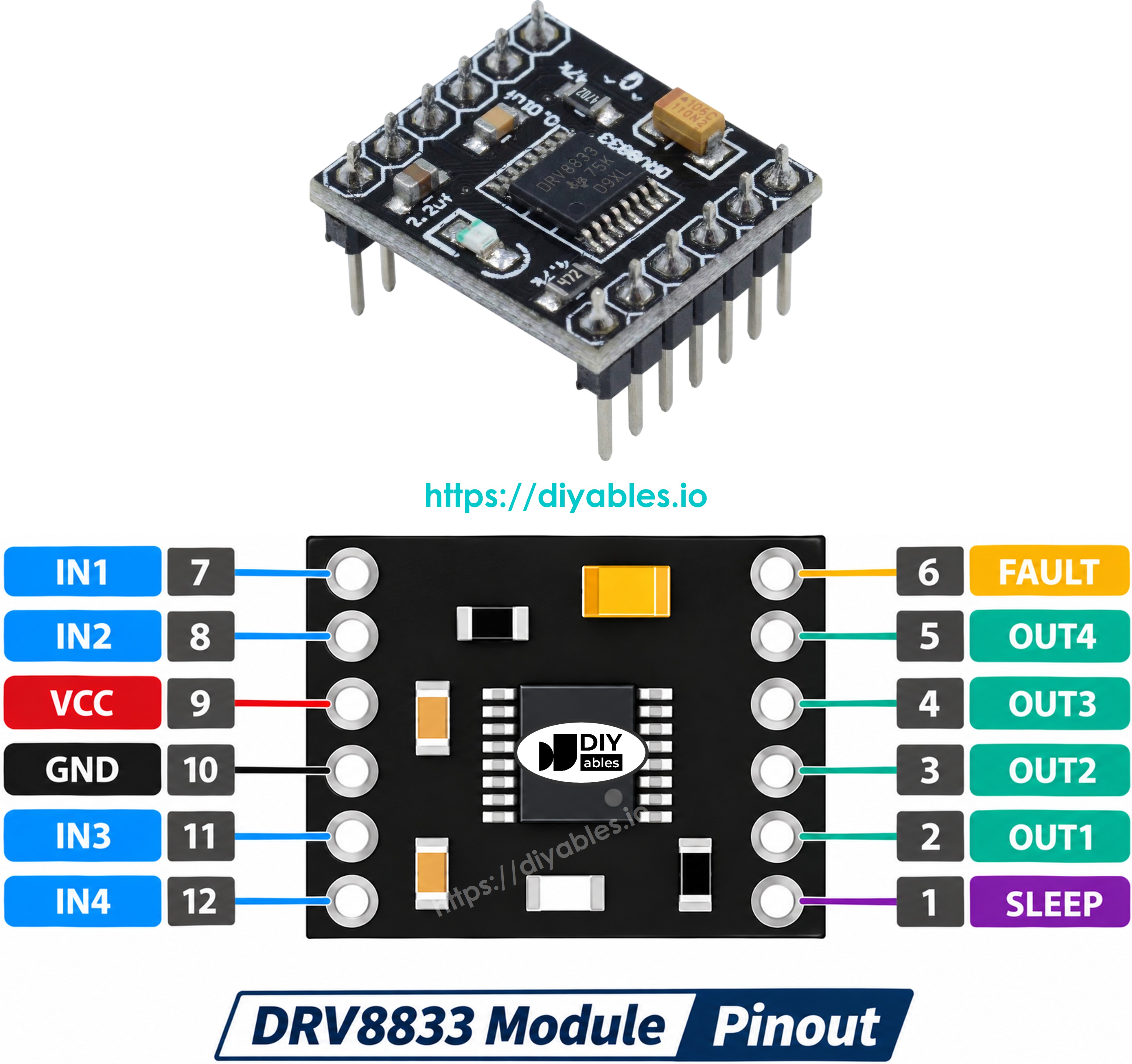
The common red or blue DRV8833 board has these pins. Labels vary between makers (some print AIN1/AIN2/BIN1/BIN2, AOUT1/AOUT2, SLP or FLT), but the jobs are the same.
- IN1, IN2: control inputs for motor A. Connect them to two PWM pins of the MKR WiFi 1010.
- IN3, IN4: control inputs for motor B. Also PWM pins.
- OUT1, OUT2: the two wires of motor A go here.
- OUT3, OUT4: the two wires of motor B go here.
- VCC: motor power, 2.7V to 10.8V, from an external supply. This is NOT the MKR's 3.3V pin.
- GND: ground. It must be shared by the motor supply, the driver and the MKR WiFi 1010.
- EEP (nSLEEP): must be HIGH to turn the driver on. LOW puts the chip to sleep and the motors will not move. In this tutorial we tie it to the MKR's VCC pin (3.3V).
- ULT (nFAULT): goes LOW when the chip detects a fault. It is optional - you can leave it unconnected.
How the IN Pins Control a Motor
Unlike the L298N, the DRV8833 has no ENA/ENB speed pins. Each motor uses just two inputs, and they set both direction and speed:
| IN1 | IN2 | Motor A does |
|---|---|---|
| LOW | LOW | Coast (free-runs to a stop) |
| HIGH | LOW | Forward |
| LOW | HIGH | Reverse |
| HIGH | HIGH | Brake (fast stop) |
Motor B works the same way with IN3 and IN4.
Speed control: to go forward at part speed, send a PWM signal to IN1 and keep IN2 LOW. To reverse at part speed, keep IN1 LOW and send PWM to IN2. That is why both IN pins of a motor must be PWM-capable. On the MKR WiFi 1010, pins 0 to 8, 10, 12, A3 and A4 support PWM, and analogWrite() takes a value from 0 to 255.
※ NOTE THAT:
MKR tip: the MKR WiFi 1010 uses a SAMD21 chip. In our code we set the IN pins with analogWrite() only - analogWrite(pin, 0) for LOW and analogWrite(pin, 255) for HIGH - and do not mix in digitalWrite() on the same pin. This keeps every pin in PWM mode and the behavior predictable.
PART 1: Control One DC Motor with DRV8833
Wiring Diagram
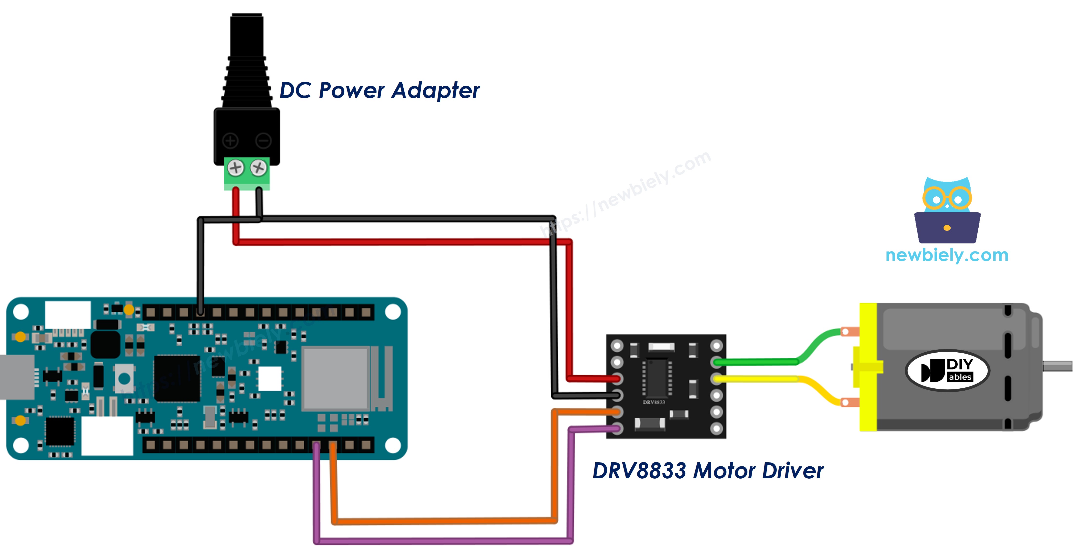
This image is created using Fritzing. Click to enlarge image
| DRV8833 Pin | Connect To |
|---|---|
| IN3 | MKR WiFi 1010 pin D3 |
| IN4 | MKR WiFi 1010 pin D2 |
| IN1, IN2 | Not connected |
| EEP | MKR WiFi 1010 VCC pin (3.3V) |
| GND | MKR WiFi 1010 GND and power supply (-) |
| VCC | 5V power supply (+), through the DC power jack |
| OUT3, OUT4 | The two DC motor wires |
| ULT | Not connected |
In this part the motor uses channel B of the driver (IN3/IN4 and OUT3/OUT4). Channel A is free for the second motor in Part 2.
Power notes:
- Power the motor from the 5V adapter through the DC power jack. A 4 x AA battery pack (about 6V) also works.
- Never take motor power from the MKR's 5V or VCC pins. Motor current spikes can reset or damage the board.
- Keep the grounds connected together. Without a common ground, the driver cannot understand the MKR's signals.
- The MKR WiFi 1010 itself can stay on USB power.
How To Program
- Give the two control pins clear names:
- Set them as outputs in setup():
- Spin forward at about half speed (PWM on IN3, IN4 LOW):
- Spin in reverse at about half speed (IN3 LOW, PWM on IN4):
- Stop. Coast = both LOW, brake = both HIGH:
The full sketch puts this into one helper, motorB(speed). A positive speed means forward, a negative speed means reverse, and 0 means coast.
Arduino MKR WiFi 1010 Code - One DC Motor
What the Code Does:
- Speeds the motor up from 0 to full speed, forward
- Holds full speed for 2 seconds
- Lets the motor coast to a stop
- Runs in reverse at about 70% speed
- Brakes hard, then repeats
- Prints each step to the Serial Monitor
Detailed Instructions
New to Arduino MKR WiFi 1010? Do our Getting Started with Arduino MKR WiFi 1010 tutorial first to set up the Arduino IDE.
Step 1: Build the Circuit
- Wire the MKR WiFi 1010, the DRV8833 and the motor as in the diagram above
- Check twice that EEP goes to 3.3V and all GNDs are joined
- Leave the 5V adapter unplugged for now
Step 2: Upload the Code
- Connect the MKR WiFi 1010 to your computer with the Micro USB cable
- Open the Arduino IDE and select the Arduino MKR WiFi 1010 board and its COM port
- Copy the code above and paste it into the Arduino IDE
- Click the Upload button
Step 3: Power the Motor and Watch
- Plug in the 5V adapter
- Open the Serial Monitor and set the baud rate to 9600
- Watch the motor speed up, coast, run backward and brake
Expected Serial Monitor Output:
If the motor turns the wrong way, just swap its two wires on OUT3 and OUT4.
PART 2: Control Two DC Motors with DRV8833
Now use both H-bridges. With a motor on each side, you have the drive system of a small two-wheel robot car. Motor A is the left wheel and motor B is the right wheel.
Wiring Diagram
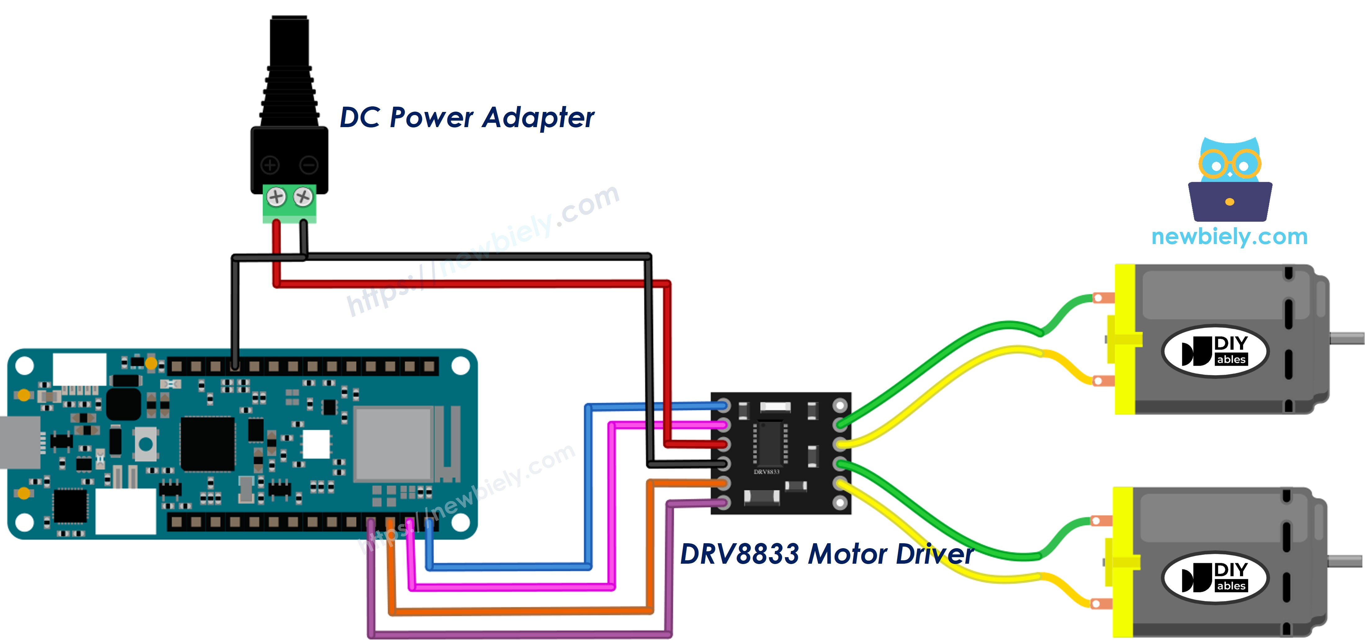
This image is created using Fritzing. Click to enlarge image
Keep the Part 1 wiring (motor B on OUT3/OUT4) and add the second motor, motor A, on OUT1/OUT2:
| DRV8833 Pin | Connect To |
|---|---|
| IN1 | MKR WiFi 1010 pin D5 |
| IN2 | MKR WiFi 1010 pin D4 |
| IN3 | MKR WiFi 1010 pin D3 |
| IN4 | MKR WiFi 1010 pin D2 |
| EEP | MKR WiFi 1010 VCC pin (3.3V) |
| GND | MKR WiFi 1010 GND and power supply (-) |
| VCC | 5V power supply (+) |
| OUT1, OUT2 | Motor A (left wheel) |
| OUT3, OUT4 | Motor B (right wheel) |
D5, D4, D3 and D2 are all PWM pins on the MKR WiFi 1010, so both motors get full speed control.
How a Two-Motor Car Moves
| Action | Motor A (left) | Motor B (right) |
|---|---|---|
| Forward | Forward | Forward |
| Backward | Reverse | Reverse |
| Turn left | Reverse | Forward |
| Turn right | Forward | Reverse |
| Stop | Coast | Coast |
Turning by running the wheels in opposite directions is called a "tank turn". The car spins in place, which is handy in tight spaces.
Arduino MKR WiFi 1010 Code - Two DC Motors
What the Code Does:
- Uses one shared function, setChannel(), for both H-bridges
- Gives each motor a short helper: motorA(speed) and motorB(speed), from -255 to 255
- Drives forward, backward, turns left, turns right, then stops
- Prints every action to the Serial Monitor
Detailed Instructions
- Add motor A and the IN1/IN2 wires as shown in the diagram
- Connect the MKR WiFi 1010 to your computer with the USB cable
- Paste the code into the Arduino IDE and click Upload
- Plug in the motor power supply
- Open the Serial Monitor at 9600 baud
- Lift the car (or watch the wheels on the desk) and check each move matches the printed action
Expected Serial Monitor Output:
Tuning tips:
- If one wheel turns backward during "Car: forward", swap that motor's two wires.
- If the car turns too fast, lower TURN_SPEED in the code.
- Very low PWM values (below about 60) may not give cheap motors enough power to start. Find your motor's lowest working speed by testing.
Troubleshooting
Motor does not move at all:
- Check that EEP is connected to 3.3V. If EEP is LOW or floating, the chip sleeps.
- Check that the 5V supply is plugged in and reaches the DRV8833 VCC pin.
- Make sure the MKR GND and the supply GND are joined.
Motor moves, then stops by itself:
- The driver may be protecting itself from too much current or heat. Use a smaller motor, lower the speed, or let the chip cool.
- If you connected ULT to an input pin, a LOW reading means a fault.
MKR WiFi 1010 resets when the motor starts:
- The motor is probably powered from the board. Move motor power to the external supply.
Motor only hums at low speed:
- The PWM value is too low for this motor to start. Raise the minimum speed.
Challenge Yourself
- Smooth stops: Ramp the speed down before stopping instead of braking.
- Speed knob: Read a potentiometer with analogRead() and map it to -255 ... 255 for forward and reverse.
- Fault alarm: Wire ULT to an input pin with INPUT_PULLUP and print a warning when it goes LOW.
- Remote control: Use the MKR's WiFi to send forward/back/left/right commands from a web page.
- Power saving: Connect EEP to a free pin instead of 3.3V, and put the driver to sleep when the car is parked.