
Raspberry Pi Pico - Slide Switch
Many Pico projects need a setting that stays put. A Pico W weather logger may need "WiFi on" or "WiFi off". A reaction game may need "easy" or "hard". A night light may need "auto" or "always on". A push button forgets your choice the moment you take your finger away, but a slide switch keeps it until you move it again. The DIYables Mini Slide Switch SS12D10 is a tiny switch of this kind, and the Pico needs only one GPIO pin to read it.
In this guide, we will learn to set up and use the Mini Slide Switch SS12D10 with the Raspberry Pi Pico. We will cover the following details:
- How the three pins of the slide switch are joined inside, and why the middle pin is the one to watch.
- How to wire the switch to GP0 of the Raspberry Pi Pico with three wires and no resistor.
- How to print the starting position, and then one numbered line for each move of the handle, with a 50 ms debounce.
- How to get by with only two wires by turning on the Pico's own pull-up resistor with Pin.PULL_UP.
https://newbiely.com/images/cover/raspberry-pi-pico-slide-switch.jpg
Hardware Preparation
| 1 | × | Raspberry Pi Pico W | |
| 1 | × | Raspberry Pi Pico Alternatively, | |
| 1 | × | Micro USB Cable | |
| 1 | × | Mini Slide Switch SS12D10 | |
| 1 | × | Breadboard | |
| 1 | × | Jumper Wires | |
| 1 | × | Recommended: Screw Terminal Expansion Board for Raspberry Pi Pico |
Or you can buy the following kits:
| 1 | × | DIYables Sensor Kit (18 sensors/displays) |
Additionally, some of these links are for products from our own brand, DIYables .
Overview of Slide Switch
The SS12D10 is a two-position switch. On top, a short 5 mm handle moves left or right under your fingertip. Underneath, three metal pins stand in one row. Slide the handle to one end and it stays there. This is called a latching switch. A push button is the opposite: a spring pushes its cap up again when your finger leaves it. Shops list this type as SPDT (single pole, double throw) or 1P2T. Both names describe a single common pin that can connect to either of two other pins.
Inside the body, a small metal bridge rides along with the handle. One side of the bridge always rests on the middle pin, COM. The other side rests on the outer pin at the handle's end. So the handle simply chooses which outer pin COM is joined to.
| Mini Slide Switch SS12D10 | |
|---|---|
| Contact Type | SPDT (1P2T), 2 positions |
| Pins | 3 in a row, 4.7mm pitch |
| Terminal Length | 6.9mm |
| Handle | 5mm |
| Body Size | about 12.8 x 6.7 x 18.2mm |
| Mounting | vertical, through-hole |
| Contacts | silver-plated brass |
| Contact Rating | AC 125V 2A |
| Switching Life | more than 100,000 cycles |
| Operating Temperature | -25°C to 80°C |
The 125 volts, 2 amps rating tells you the most that the contacts can switch. On the Pico, the switch only carries a tiny signal into one GPIO pin, so it works far below that limit.
Pinout
The switch has no printed labels. Hold it so that you can see the three pins in a row: the pin in the middle is COM, and the pins at the two ends are pin 1 and pin 3.
- Pin 1 (outer pin): connect to GND (0 volts).
- Pin 2, COM (middle pin): connect to a GPIO pin of the Pico. It always has the same voltage as the outer pin that the handle joins it to.
- Pin 3 (outer pin): connect to 3V3(OUT) (3.3 volts) in the 3-wire wiring. In the 2-wire wiring, leave it free.
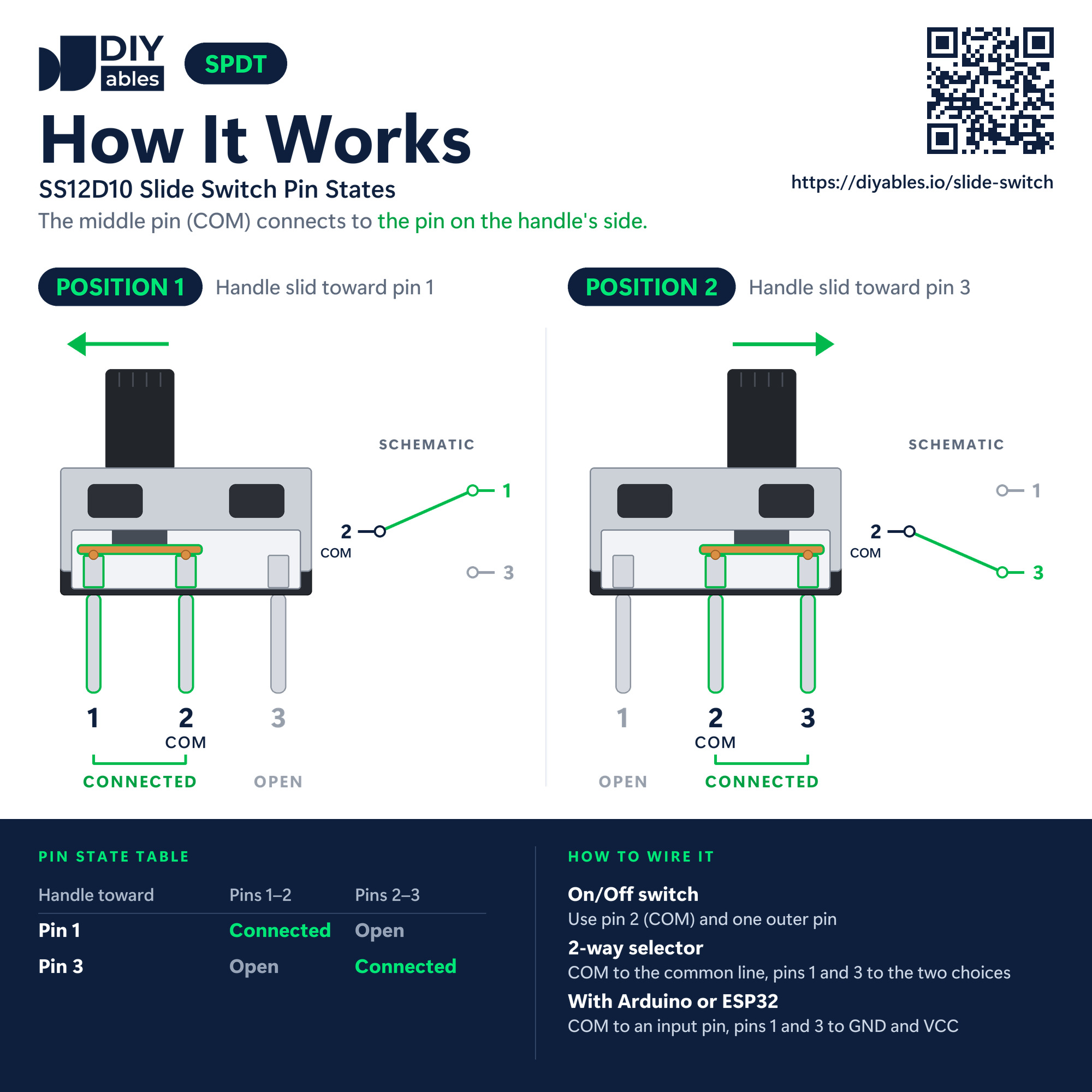
The picture shows the two handle positions:
- Position 1, handle toward pin 1: pin 1 and COM are joined. Pin 3 is open.
- Position 2, handle toward pin 3: COM and pin 3 are joined. Pin 1 is open.
With pin 1 on GND and pin 3 on 3.3 volts, COM jumps between 0 volts and 3.3 volts each time you move the handle. In MicroPython, value() then gives 1 at the pin 3 end (we call it ON) and 0 at the pin 1 end (we call it OFF). The two outer pins are the same inside. If you swap their wires, the switch still works, but ON moves to the other end.
The metal bridge does not land cleanly when it slides. For a few milliseconds it touches, lets go and touches again. The Pico is fast enough to catch every one of these tiny jumps, so the script looks at the pin a second time, 50 ms later, before it believes that the handle really moved.
This switch has two cousins on this site. The bigger ON/OFF rocker switch, made to sit in a hole in the wall of a box, is in Raspberry Pi Pico - Switch. A key that springs back after each press is in Raspberry Pi Pico - Button Module.
Wiring Diagram
Plug the Pico and the slide switch into the same breadboard. Count the Pico pins from the USB end. GP0 is pin 1, on the left edge. On the right edge, GND is pin 38, the third pin from the USB end, and 3V3(OUT) is pin 36, the fifth pin from the USB end. Each wire runs from the hole next to a Pico pin to a hole in the column of its switch leg. COM is always tied to 0 volts or to 3.3 volts, so GP0 never floats. No resistor is needed, and the code sets GP0 as a plain Pin.IN.
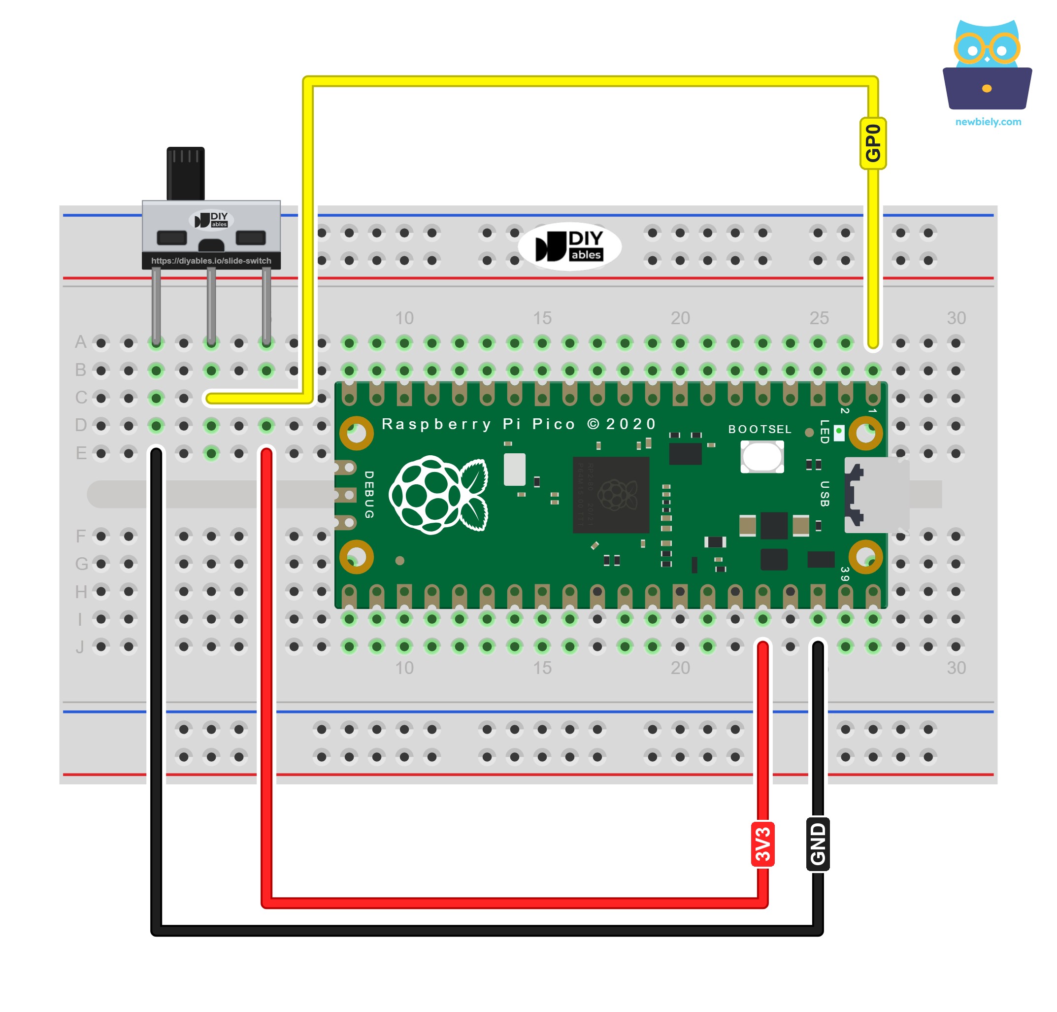
This image is created using Fritzing. Click to enlarge image
| Slide Switch Pin | Raspberry Pi Pico Pin |
|---|---|
| Pin 1 | GND (pin 38) |
| Pin 2 (COM) | GP0 (pin 1) |
| Pin 3 | 3V3(OUT) (pin 36) |
※ NOTE THAT:
Pin 3 must get its 3.3 volts from 3V3(OUT) only. Stay away from VBUS (pin 40) and VSYS (pin 39). They carry about 5 volts from the USB cable, and when the handle is at the pin 3 end, COM would pass that 5 volts straight into GP0. The GPIO pins of the Pico are made for 3.3 volts.
Also keep GP0 an input. If another script sets it to Pin.OUT, the switch connects that output directly to 3.3 volts or to GND, which is a short circuit.
Raspberry Pi Pico Code - Slide Switch
This script reads GP0 once when it starts and tells you where the handle is. Then it stays quiet. Each time the handle reaches the other end, it prints one numbered line. Every line also shows the raw value of GP0 in brackets, so you can see which number belongs to ON and which to OFF. A change only counts if GP0 still shows it 50 ms later, so contact bounce never adds an extra line.
Detailed Instructions
Please follow these instructions step by step:
- Ensure that Thonny IDE is installed on your computer.
- Ensure that MicroPython firmware is installed on your Raspberry Pi Pico.
- If this is your first time using a Raspberry Pico, refer to the Raspberry Pi Pico - Getting Started tutorial for detailed instructions.
- Put the Pico and the switch on the breadboard, then add the three jumper wires listed in the table. Check once more that pin 3 goes to 3V3(OUT), not to VBUS or VSYS.
- Connect the Raspberry Pi Pico to your computer using a USB cable.
- Launch the Thonny IDE on your computer.
- On Thonny IDE, select MicroPython (Raspberry Pi Pico) Interpreter by navigating to Tools Options.
- In the Interpreter tab, select MicroPython (Raspberry Pi Pico) from the drop-down menu.
- Ensure the correct port is selected. Thonny IDE should automatically detect the port, but you may need to select it manually (e.g., COM3 on Windows or /dev/ttyACM0 on Linux).
- Copy the above code and paste it to the Thonny IDE's editor.
- Save the script to your Raspberry Pi Pico by:
- Click the Save button, or use Ctrl+S keys.
- In the save dialog, you will see two sections: This computer and Raspberry Pi Pico. Select Raspberry Pi Pico
- Save the file as main.py
- Push the handle to the pin 1 end.
- Click the green Run button (or press F5) to run the script. The script will execute.
- Slide the handle to the pin 3 end, back to pin 1, and then to pin 3 again. Wait about one second at each end.
- Read the lines in the Shell at the bottom of Thonny:
There is one numbered line per slide, and nothing in between. If the Shell says OFF all the time, look at the wire from pin 3 to 3V3(OUT). If it says ON all the time, look at the GND wire on pin 1. If lines appear while nobody touches the handle, a wire is loose and GP0 is floating.
If you name your script main.py and save it to the root directory of the Raspberry Pi Pico, it will automatically run each time the Pico is powered on or reset.
Raspberry Pi Pico Code - Slide Switch with the Internal Pull-up (2 Wires)
Sometimes 3V3(OUT) is already busy with a display or a sensor, or you simply want fewer wires. Every GPIO pin of the Pico has a pull-up resistor inside the chip. Pin.PULL_UP turns it on, and then it does the job of the pin 3 wire.
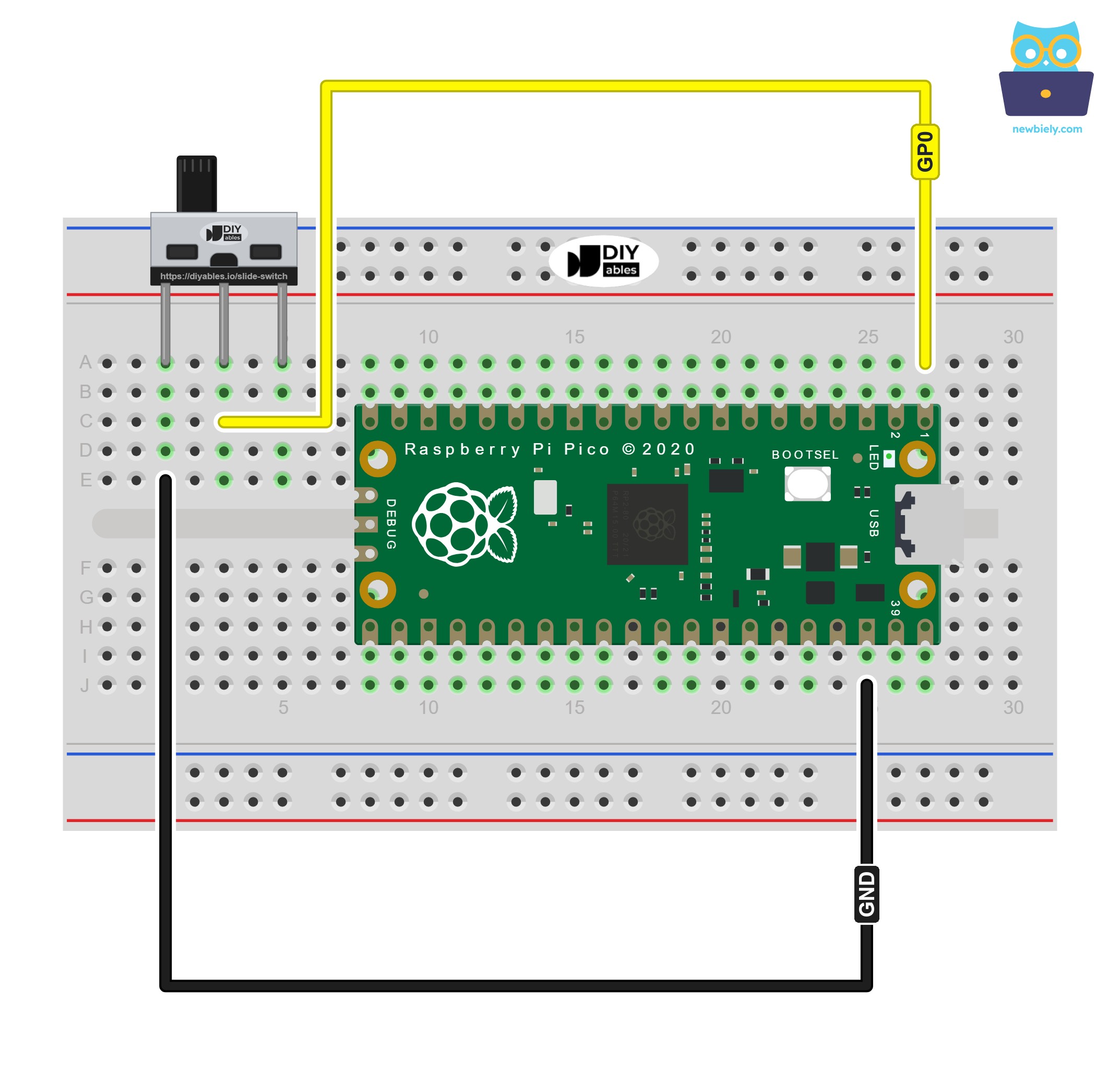
This image is created using Fritzing. Click to enlarge image
| Slide Switch Pin | Raspberry Pi Pico Pin |
|---|---|
| Pin 1 | GND (pin 38) |
| Pin 2 (COM) | GP0 (pin 1) |
| Pin 3 | not connected |
In this wiring, the switch closes a circuit at one end only. That end is the real ON side, so the logic is flipped: 0 means ON and 1 means OFF.
- Handle toward pin 1: COM joins GP0 to GND, so value() gives 0. The script prints ON.
- Handle toward pin 3: pin 3 has no wire, so COM is joined to nothing. The resistor inside the Pico then pulls GP0 up to 1. The script prints OFF.
Detailed Instructions
- Click the red Stop button in Thonny to end the first script.
- Just remove the pin 3 wire. The GND wire and the GP0 wire stay where they are.
- Replace the code in the editor with the script above and save it to the Raspberry Pi Pico as main.py.
- Push the handle to the pin 1 end, then click the green Run button (or press F5).
- Slide the handle three times: to pin 3, to pin 1, and to pin 3.
Now put the two Shell outputs side by side:
| Handle Position | 3 Wires (Pin.IN) | 2 Wires (Pin.PULL_UP) |
|---|---|---|
| Toward pin 1 | GP0 = 0, OFF | GP0 = 0, ON |
| Toward pin 3 | GP0 = 1, ON | GP0 = 1, OFF |
Surprise: GP0 gives the same numbers in both wirings. Only the meaning changes, and the script decides it. Pick the way you like: the 3-wire way reads more naturally in code, and the 2-wire way leaves 3V3(OUT) free for other parts.