
ESP32 MicroPython BTS7960 Motor Driver
This tutorial instructs you how to use a BTS7960 high-current motor driver with the ESP32 and MicroPython. Our project in mind is a motorized roller blind. A 12V tube motor winds the fabric up when the day starts and lets it down at night. A tall, heavy blind makes that motor pull far more current than small driver boards can handle, and the DIYables BTS7960 module is built for this kind of load. In detail, we will learn:
- Which job each part of the BTS7960 board has, and why only six of its eight header pins get a wire.
- Why VCC on the module goes to VIN of the ESP32 (the 5V from USB), while the motor runs on a separate 12V adapter.
- How to hook up the ESP32, the module, the 12V motor and its power jack with jumper wires only, no breadboard.
- How machine.PWM and duty_u16() pick the speed and the direction, and how a brake stop differs from a coast stop.
- How to follow the motor in the Thonny Shell, and how the Stop/Restart button leaves the driver switched off.
Hardware Preparation
Or you can buy the following kits:
| 1 | × | DIYables ESP32 Starter Kit (ESP32 included) | |
| 1 | × | DIYables ESP32 S3 Starter Kit (ESP32 S3 included) | |
| 1 | × | DIYables Sensor Kit (18 sensors/displays) |
Additionally, some of these links are for products from our own brand, DIYables .
Overview of BTS7960 Motor Driver
A GPIO pin of the ESP32 can only give 3.3 volts and a few milliamps. That is fine for a signal, but nowhere near enough to turn a 12V blind motor. On top of that, the motor wants its current reversed: one way to wind the blind up, the other way to let it down. The BTS7960 module sits between the two and does the heavy work. Its two black power chips are Infineon BTS7960B parts, and a large finned heat sink is fixed underneath the board to keep them cool. You may find it in shops as IBT-2 or HW-039 too.
Inside, each BTS7960B works as a half-bridge, which means it can tie one motor lead either to +12V or to 0V. With one chip on each lead, the two chips add up to one full H-bridge. Lead A on +12V and lead B on 0V: the shaft spins one way. Lead A on 0V and lead B on +12V: it spins the other way. For the speed, PWM is used. In our script, the ESP32 flicks the signal on and off a thousand times per second. If the signal stays on for most of each cycle, the duty cycle is high and the motor runs fast. If it is on only briefly, the motor runs slowly.
| BTS7960 Module | |
|---|---|
| Power stage | 2 x BTS7960B half-bridges = 1 full H-bridge |
| Load | a single brushed DC motor, forward or reverse |
| Peak current | 43A (the chip starts limiting here) |
| Motor supply | 5.5V to 27V DC on B+ / B- (6V, 12V or 24V motors) |
| Max PWM on RPWM / LPWM | 25 kHz |
| Safety features | current limiting, over-temperature protection |
| Input stage | 74HC14 buffer chip (gets its power from VCC) |
| Sense outputs | R_IS and L_IS (current / fault signal) |
Do not plan with 43A. It is a peak: at that level, the chip's own current limit steps in. A blind motor runs for a while on every trip, so choose a motor whose normal current is far lower. How many amps the board can give for minutes at a time is decided by the heat sink.
Driving a small robot car instead? Then this board is more than you need, and the DRV8833 tutorial for ESP32 MicroPython is the simpler path. The well-known L298N handles two motors, but only about 2A each, and around 2 volts get lost inside it. The BTS7960 takes just one motor, yet it passes far more current with almost no voltage loss.
Pinout
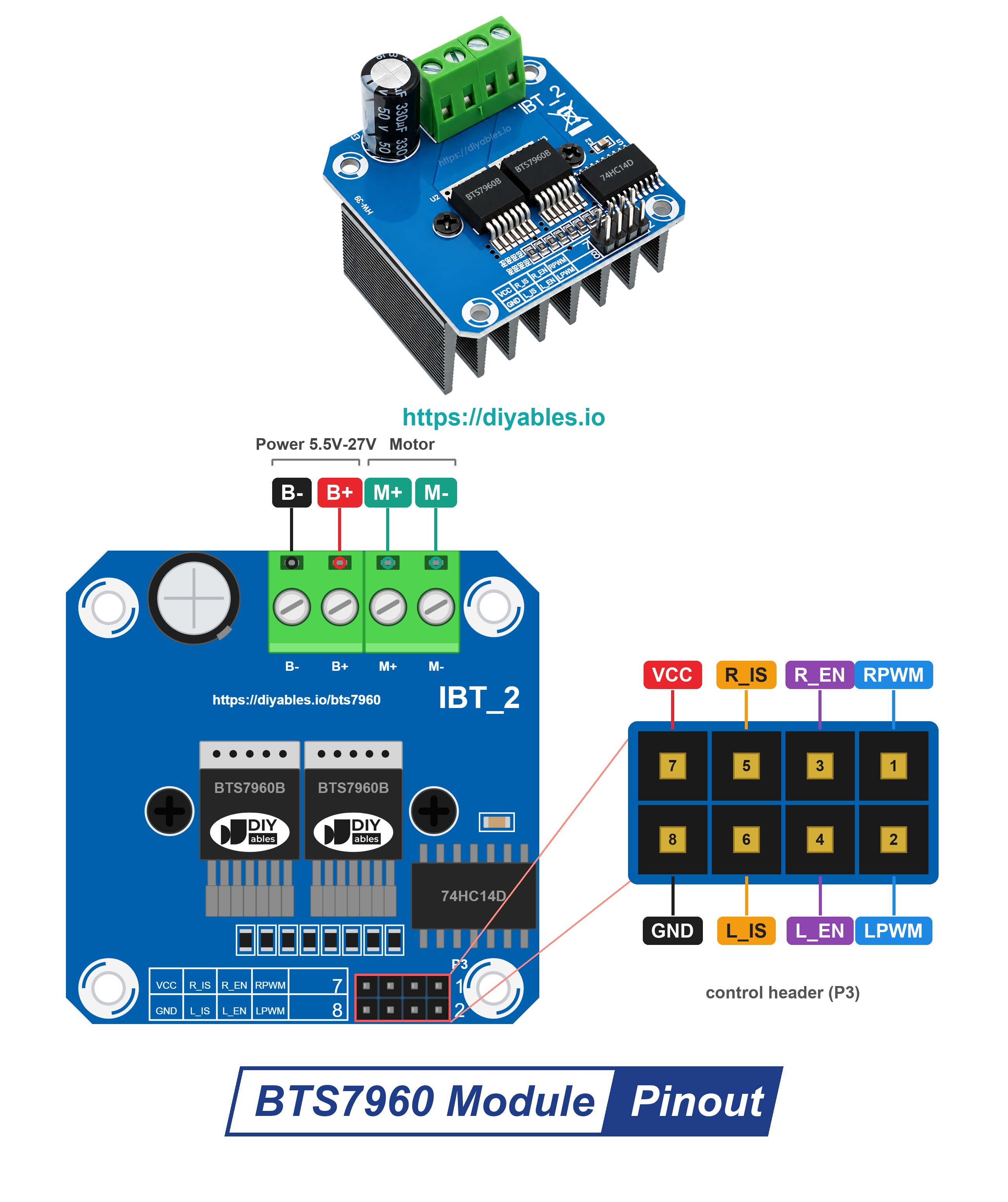
Eight male pins, arranged 2 x 4, form the control header, marked P3 on the board. As printed next to it, the upper row is VCC, R_IS, R_EN, RPWM, and the lower row is GND, L_IS, L_EN, LPWM. R pins serve the right half-bridge and L pins the left one, and each pair is stacked one above the other. Two labels are cut short on the board: R_IS shows as "R_S" and L_IS as "L_S". Between these pins and the power chips sits a 74HC14 buffer (called the isolation chip on the product page).
- RPWM pin: connect to GPIO16. PWM on this pin turns the motor forward. It is the input of the right half-bridge.
- LPWM pin: connect to GPIO17. PWM on this pin turns the motor backward. It is the input of the left half-bridge.
- R_EN pin: connect to GPIO19. HIGH wakes the right half-bridge up, LOW shuts it down.
- L_EN pin: connect to GPIO18. HIGH wakes the left half-bridge up, LOW shuts it down.
- R_IS and L_IS pins: no wire on this page. They report the motor current or a fault, and we do not read them here.
- VCC pin: connect to VIN (5 volts from USB). Only the 74HC14 and the small power LED run from it, so no motor current passes through it.
- GND pin: connect to one of the GND pins (0 volts) of the ESP32. Inside the module, it is the same point as B-.
- B+ and B- terminals: input for the motor supply, anything from 5.5 volts to 27 volts. In our setup, the 12V adapter feeds them via the DC power jack.
- M+ and M- terminals: the two leads of the motor are screwed in here.
Up, Down, Brake and Coast
duty_u16() takes a number between 0 and 65535. 0 keeps the pin LOW the whole time, 65535 keeps it HIGH the whole time, and 32768 is a 50% duty cycle. This is what each mix of the four control pins does. In the blind example, forward rolls the fabric up and reverse lets it down:
| Enables (R_EN, L_EN) | RPWM (GPIO16) | LPWM (GPIO17) | Result |
|---|---|---|---|
| HIGH | duty_u16 above 0 | 0 | forward (blind up) - more duty, more speed |
| HIGH | 0 | duty_u16 above 0 | reverse (blind down) - more duty, more speed |
| HIGH | 0 | 0 | brake - the driver ties both motor leads together, and the shaft halts quickly |
| LOW | 0 | 0 | coast - the driver is off; the shaft keeps turning and slowly stops |
A rule for any code you write later: RPWM and LPWM must never carry PWM together. One of them always stays at 0. The helper functions in the script below always clear the opposite pin before they start a new direction.
For the blind, use the brake when the fabric reaches its end position. The motor halts right there instead of drifting on.
Logic Power and Motor Power
The module is fed from two places:
- 5 volts for the logic: VCC and GND on the header, wired to VIN and GND of the ESP32. VIN passes on the 5 volts of the USB cable. The 74HC14 is the only thing on VCC, and the module maker specifies 5V for it. For its inputs, a 3.3V HIGH is enough, so the GPIO pins of the ESP32 connect straight to them.
- 12 volts for the motor: B+ and B- on the big screw terminal, fed by the adapter. Its amp rating must be above the current of your motor.
- One ground for all: the module connects GND to B- on its own board. That is why one wire between the GND pins of both boards already links the ESP32 to the ground of the 12V adapter. No wire to B- is needed.
- A one-way street: the four control inputs only have pull-down resistors, and R_IS and L_IS stay unwired. So no signal travels back to the ESP32, and 5 volts has no way to get into a GPIO pin.
Wiring Diagram
This build needs no breadboard. Six jumper wires run straight from the ESP32 board to header P3 of the module. Since the pins on both boards stick out as male pins, pick jumper wires with sockets (female ends) on both sides. Look at the picture: the four signal wires (GPIO16, GPIO17, GPIO18 and GPIO19) and the black GND wire all leave from one header of the ESP32. The red VIN wire is the odd one: it starts on the opposite header.
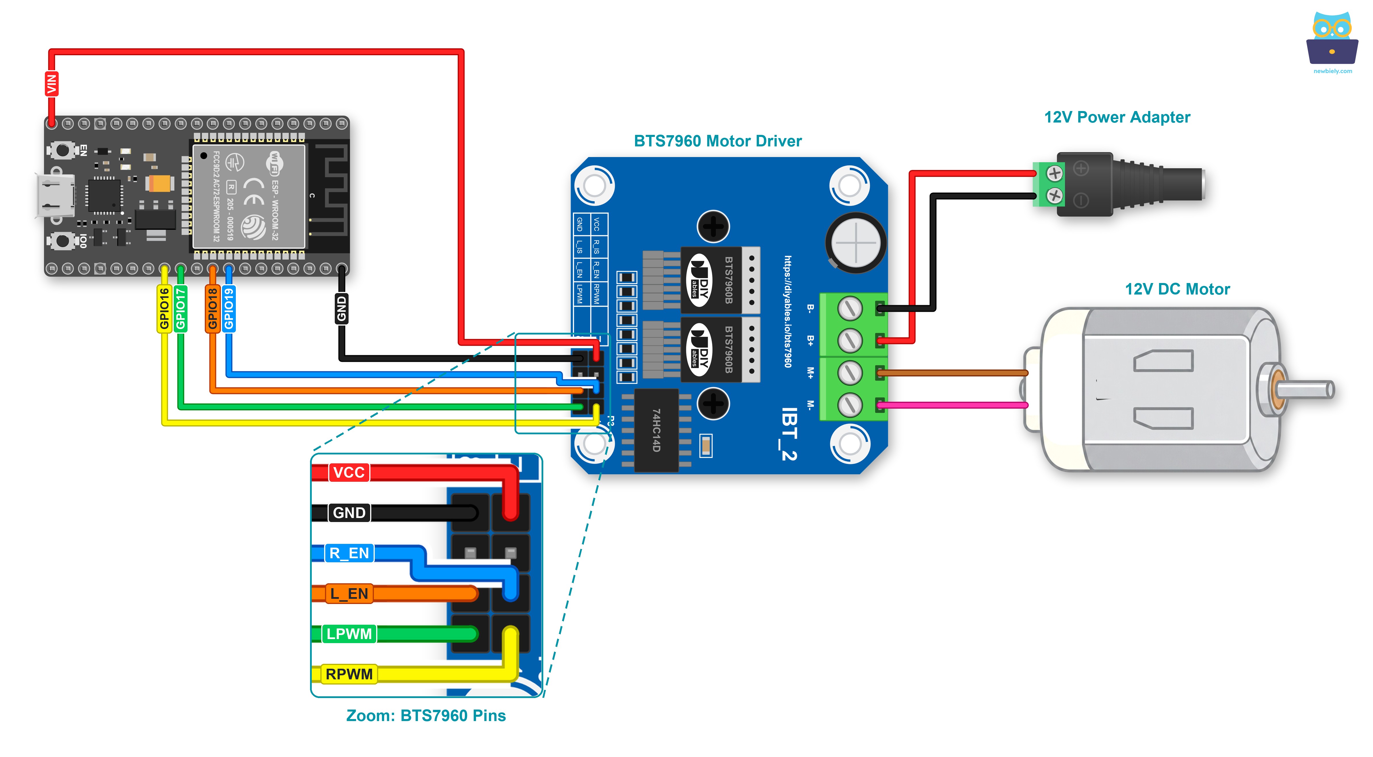
This image is created using Fritzing. Click to enlarge image
| Module Pin | Goes To |
|---|---|
| VCC | ESP32 VIN (5 volts from USB) |
| GND | ESP32 GND |
| R_EN | ESP32 GPIO19 |
| L_EN | ESP32 GPIO18 |
| RPWM | ESP32 GPIO16 |
| LPWM | ESP32 GPIO17 |
| R_IS, L_IS | nothing (left open) |
| B+ | DC power jack, + screw |
| B- | DC power jack, - screw |
| M+, M- | motor leads (either way round) |
※ NOTE THAT:
Twelve volts sit on B+. Never let that wire touch any ESP32 pin, VIN included: VIN only carries the 5V of the USB cable. Before the first power-on, read the polarity printed on the DC power jack, because B+ and B- the wrong way round can damage the module. Make the 12V connection as the very last step.
ESP32 MicroPython Code - BTS7960 Motor Driver
Nothing to install: machine.PWM and machine.Pin come with MicroPython. How the script is built:
- First, GPIO19 and GPIO18 go LOW. The driver is off while GPIO16 and GPIO17 are turned into 1 kHz PWM outputs at duty 0. Then driver_on() raises R_EN and L_EN.
- to_duty() maps a percentage onto duty_u16() numbers: 50 becomes 32767, and 100 becomes 65535.
- motor_forward() zeroes LPWM before it gives RPWM its duty, and motor_reverse() does the mirror image. So PWM never lands on both pins together.
- motor_brake() puts both PWM pins at 0 and leaves the driver on. motor_coast() also drops R_EN and L_EN, so nothing drives the motor any more.
- One round of the loop: a forward ramp in 5% steps (about 2 seconds), 100% held for 2 seconds, the same ramp back down, a brake (1 second), half-duty reverse (2 seconds) and a coast (2 seconds). After that, the driver is enabled again.
- The whole loop sits inside try / except KeyboardInterrupt. When you stop the script in Thonny, motor_coast() runs before the script ends.
Detailed Instructions
Here's instructions on how to set up and run your MicroPython code on the ESP32 using Thonny IDE:
- Before you start, Thonny IDE must be installed on the computer, and the ESP32 must run MicroPython.
- Missing a piece? The ESP32 MicroPython Getting Started guide sets up both.
- Wire everything as in the table. Wait with the 12V adapter: it comes last.
- Lay the motor down so it cannot roll off the table, and keep your hands clear of the shaft while it runs.
- Plug the USB cable into the ESP32 and the computer, then launch Thonny.
- From the Tools menu, open Options, then switch tabs to Interpreter and choose MicroPython (ESP32) in the list. If Thonny does not find the port, pick it by hand (COM5, /dev/ttyUSB0 or similar).
- Copy the script from this page into a new Thonny tab.
- Store it on the ESP32:
- Press Ctrl+S, or click the floppy-disk icon in the toolbar.
- When Thonny asks where, select MicroPython device.
- Call the file main.py and confirm with OK.
- Time for motor power: plug the 12V adapter into the mains socket and its barrel plug into the DC power jack.
- Press F5 to run the script (the toolbar button with the green arrow does the same).
- Now follow the motor and the Thonny Shell together:
If you name your script main.py and save it to the MicroPython device, it will run automatically every time the ESP32 is powered on.
Keep that in mind here: with this file on the board, the motor starts whenever the ESP32 gets power. Once you finish testing, remove the file from the board or give it another name.
What you should notice:
- During the first steps of line a), the shaft does not move yet. A motor needs a certain duty to overcome its own friction. A quiet hum or high whine at low speed is the 1 kHz PWM you can hear. It does no harm.
- Lines d) and f) both end the motion, but not in the same way. After d) (brake), the shaft halts almost at once. After f) (coast), it keeps turning a little and winds down slowly.
- If line a) turns the shaft the opposite way to what you want, swap the leads in M+ and M-. No code change is needed.
- Stopping is easy: use the Stop/Restart button of Thonny. The Shell shows Stop received - enables LOW, motor coasting, and the motor stops.
Project Ideas
From test bench to a real window, here are a few ways to grow this project:
- Wall buttons: two button modules, one for up and one for down. Each press calls motor_forward() or motor_reverse().
- End positions: mount a limit switch where the fabric should stop when fully open, and a second one where it should stop when fully closed. When one of them clicks, call motor_brake().
- Sunrise mode: with an LDR module the ESP32 knows when daylight comes, so the blind opens by itself in the morning and closes after dark.
- Gentle moves: start every trip at low duty and speed up step by step, the same trick the script uses, so the fabric does not jerk.