
Raspberry Pi Pico - BTS7960 Motor Driver
Every power window in a car is moved by a small 12 volt DC motor with a gearbox, the window lifter motor. Take one out of an old car door, and you have a strong little motor for a sliding hatch, a coop door or a lifting platform. The Raspberry Pi Pico can tell it when to go up and when to go down. It cannot power it, though: a GP pin only sends a weak 3.3 volt signal, while the motor pulls many amps from a 12 volt supply. The BTS7960 motor driver sits between the two.
In this guide, we will learn to set up and use the BTS7960 43A motor driver with the Raspberry Pi Pico. We will cover the following details:
- What the eight header pins and the four screw terminals of the BTS7960 module are for.
- Why the VCC pin of the module goes to VBUS (5 volts), and why the 12 volt supply never touches the Pico.
- How to plug the Pico into a breadboard and run six jumper wires to the BTS7960.
- How a MicroPython script with duty_u16() turns the motor up (forward) and down (reverse), and how a brake is different from a coast.
Hardware Preparation
Or you can buy the following kits:
| 1 | × | DIYables Sensor Kit (18 sensors/displays) |
Additionally, some of these links are for products from our own brand, DIYables .
Overview of BTS7960 Motor Driver
The DIYables BTS7960 module is a board with a big heat sink under it. Many shops sell the very same board as "IBT-2" or "HW-039". Two Infineon BTS7960B chips sit on top of the board, each of them a half-bridge. Together they form one full H-bridge. That is why a single module runs exactly one brushed DC motor, both ways, with PWM for the speed. A small 74HC14 buffer chip sits between the control header and the two power chips. It takes the signals from the Pico and hands them on.
| DIYables BTS7960 Module | |
|---|---|
| Also Sold As | IBT-2, HW-039 |
| Power Chips | 2 x Infineon BTS7960B half-bridge (one full H-bridge) |
| Motor Count | one brushed DC motor, both directions |
| Voltage for the Motor (B+, B-) | 5.5 volts to 27 volts DC, so 6, 12 or 24 volt motors |
| Peak Current | 43 A, where the chips start to limit the current |
| Highest PWM Frequency | 25 kHz (RPWM, LPWM) |
| Logic Supply (VCC) | for the 74HC14 buffer chip and power LED only |
| Built-in Protection | current limit, over-temperature |
Read the 43 A as a ceiling, not as a goal. If your motor runs for minutes at a time, keep well under that number. For long runs, the heat sink sets the real limit: the better it sheds heat, the more current the board can keep up.
How does it work? The motor sits between the two chips. Each chip has two choices for its motor wire: 12 volts from B+, or ground from B-. When the right chip picks 12 volts and the left chip picks ground, current enters the motor from the right side. Let the chips trade their choices, and the current enters from the left side instead, so the shaft turns backward. PWM switches the 12 volts on and off very fast (1000 times per second in this guide). The longer the "on" part of each cycle (the duty cycle), the faster the motor turns.
Pinout
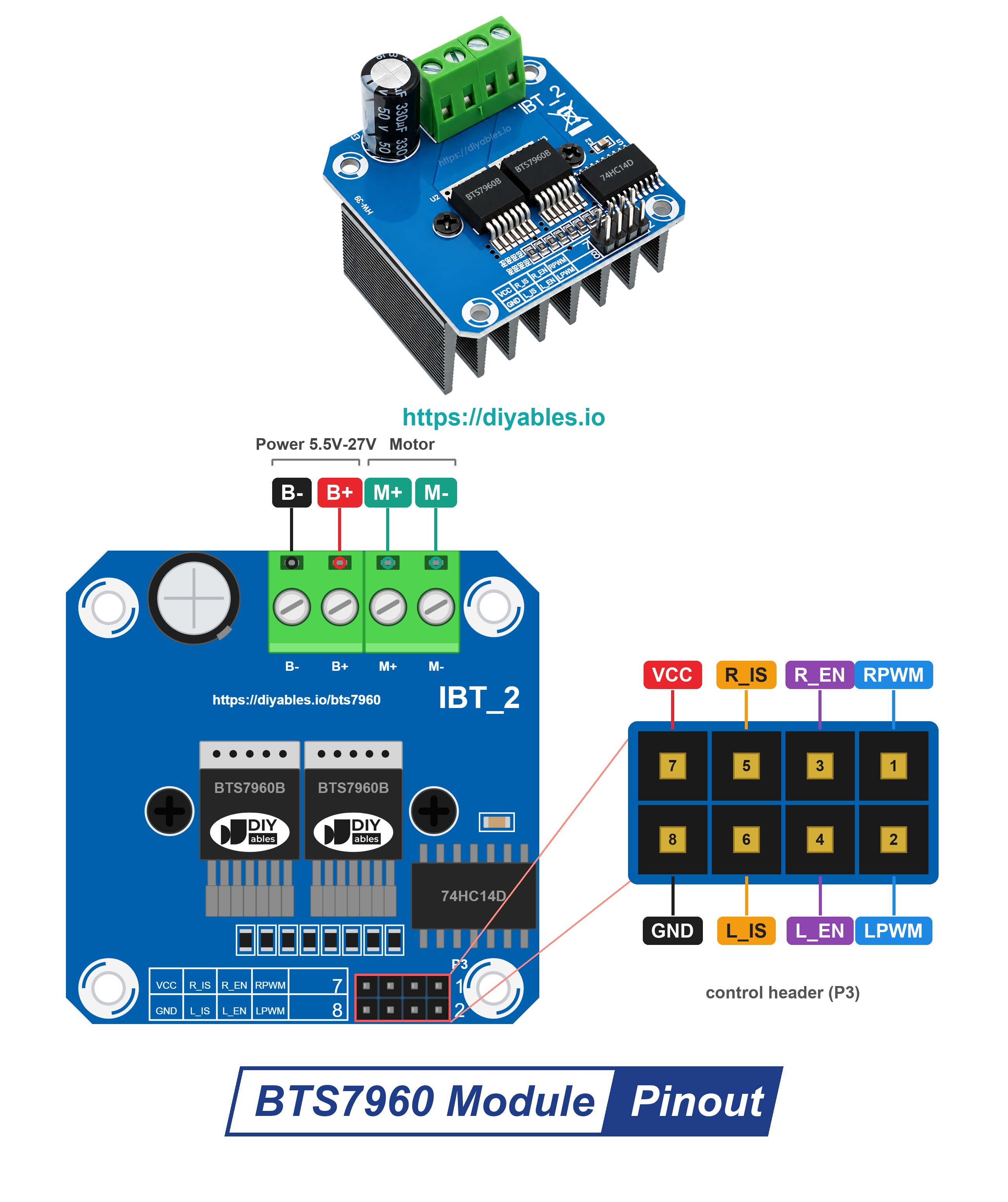
The thin control wires go to a 2 x 4 pin header, and the thick power wires go to a 4-way screw terminal. On the header, each "R" pin has its "L" partner right below it:
- Top row: VCC, R_IS, R_EN, RPWM.
- Bottom row: GND, L_IS, L_EN, LPWM.
What each pin does in this guide:
- RPWM pin: speed signal for the forward direction (we call it "up"). Connect to GP16 of the Pico.
- LPWM pin: speed signal for the reverse direction ("down"). Connect to GP17.
- R_EN pin: switches the right half-bridge on at HIGH (3.3 volts) and off at LOW (0 volts). Connect to GP19.
- L_EN pin: does the same for the left half-bridge. Connect to GP18.
- R_IS and L_IS pins: these report the motor current and faults. The silkscreen calls them "R_S" and "L_S". This guide does not use them, so no wire goes there.
- VCC pin: connect to VBUS of the Pico (5 volts when the Pico runs on USB). It only powers the logic side: the 74HC14 chip and the power LED. The motor never takes power from it.
- GND pin: connect to a ground pin (0 volts) of the Pico. Inside the module, it is tied to B-.
- B+ and B- terminals: the 12 volt supply goes here, plus to B+ and minus to B-.
- M+ and M- terminals: one motor wire in each.
Why 5 volts on VCC? VCC feeds only the small 74HC14 chip, and the maker of the module wants 5 volts there. The control inputs still accept 3.3 volt signals, so the GP pins can drive them as they are. Each input has a pull-down resistor, and R_IS and L_IS stay unconnected, so no 5 volt signal comes back from the module into the Pico.
How the Control Pins Move the Motor
| RPWM (GP16) | LPWM (GP17) | R_EN and L_EN | What the motor does |
|---|---|---|---|
| PWM | 0 | HIGH | turns forward (up). A higher duty cycle gives more speed. |
| 0 | PWM | HIGH | turns in reverse (down). A higher duty cycle gives more speed. |
| 0 | 0 | HIGH | brake. Both motor wires get tied together inside the driver, and the shaft halts quickly. |
| 0 | 0 | LOW | coast. The driver lets go of the motor completely, and it spins down slowly on its own. |
One rule matters more than any other: RPWM and LPWM must never carry PWM at the same time. At least one of them stays at 0. The script keeps this rule by setting the other pin to 0 first, every time it changes direction.
Power and Ground
- The motor is fed by the 12 volt adapter alone. The adapter's plug goes into the DC power jack, whose + screw is wired to B+ and whose - screw is wired to B-.
- Your adapter should be able to supply more current than the motor draws.
- B+ must never touch any pin of the Pico: not VSYS, not VBUS, not a GP pin.
- A single ground wire does the job. Inside the module, GND is tied to B-, so the wire from a Pico ground pin to the module's GND puts the Pico, the module and the adapter on one shared ground.
- Swapped plus and minus can ruin the module. Check the + and - screws of the jack twice before the adapter goes in.
Is the BTS7960 more than your motor needs? A DRV8833 board can run two small motors at about 1.5 A each, up to 10.8 volts. The BTS7960 runs just one motor, with far more current and up to 27 volts. For small motors, the Raspberry Pi Pico - DRV8833 DC Motor Driver and Raspberry Pi Pico - DC Motor tutorials, which both use the DRV8833, are a better fit.
Wiring Diagram
The Pico is plugged into the breadboard. In the drawing, its USB connector points to the right, so pins 21 to 40 run along the lower edge. Each jumper wire starts in the bottom row of holes, just below its Pico pin, and ends on the header of the BTS7960. The module itself stays off the breadboard: it has its own pin header, so the wires go straight to it. Four of the six wires leave close together, at the end far from the USB connector: GP16 (pin 21), GP17 (pin 22), GP18 (pin 24) and GP19 (pin 25). The GND wire comes from pin 38 on the same edge, near the USB end. The red 5 volt wire comes from VBUS, pin 40, the very last pin at the USB end.
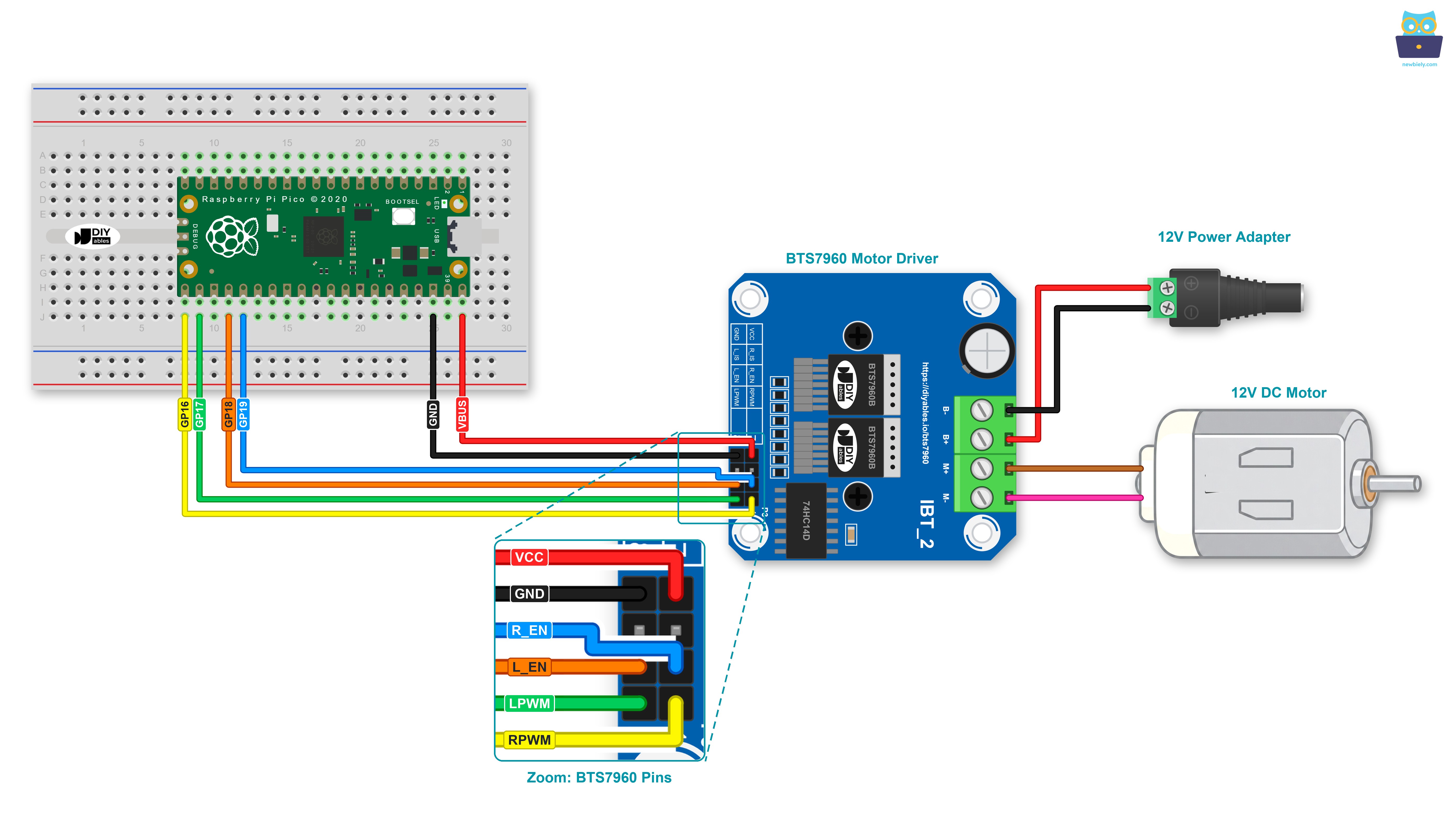
This image is created using Fritzing. Click to enlarge image
| BTS7960 Module | Raspberry Pi Pico / Other Part |
|---|---|
| RPWM | GP16 (pin 21) |
| LPWM | GP17 (pin 22) |
| R_EN | GP19 (pin 25) |
| L_EN | GP18 (pin 24) |
| VCC | VBUS (pin 40) |
| GND | GND (pin 38) |
| R_IS, L_IS | not wired |
| B+ | the plus (+) screw of the DC power jack (12 volt adapter) |
| B- | the minus (-) screw of the DC power jack |
| M+, M- | motor wire 1 and motor wire 2 |
※ NOTE THAT:
Keep the 12 volt side and the Pico side apart. The adapter connects only to B+ and B-, and the Pico gets its own power from the USB cable. Plug in the adapter last, when every jumper wire is already in place.
Raspberry Pi Pico Code - BTS7960 Motor Driver
This script is a bench test for the window motor. GP16 and GP17 become PWM outputs at 1 kHz, and GP18 and GP19 become plain on/off outputs. Speeds are written in percent. up(percent) and down(percent) turn 0 to 100 % into the 0 to 65535 range of duty_u16(), and each of them sets the opposite PWM pin to 0 before it starts. brake() and coast() are the two ways to stop from the table above, and enable() switches R_EN and L_EN together. One round of the loop goes like this:
- UP: the speed climbs from 0 % to 100 % in steps of 4 %.
- UP: full speed for 2 seconds.
- UP: the speed drops back to 0 %.
- BRAKE: 1 second.
- DOWN: half speed (50 %) for 2 seconds.
- COAST: the driver is off for 2 seconds, then on again for the next round.
The try / finally part turns the driver off when you click Stop in Thonny, so the motor does not keep running by itself.
Detailed Instructions
Please follow these instructions step by step:
- Ensure that Thonny IDE is installed on your computer.
- Ensure that MicroPython firmware is installed on your Raspberry Pi Pico.
- Never set up a Pico before? The Raspberry Pi Pico - Getting Started tutorial explains both steps.
- Wire the Pico, the BTS7960, the motor and the DC power jack as the diagram shows. Keep the 12 volt adapter out of the socket for now.
- Clamp or tape the motor down on the table. A geared window motor has a lot of force when it starts.
- Test on the bench, not inside a car door. This test runs up for longer than it runs down, so in a door the glass would soon reach the top and the motor would stall.
- Connect the Raspberry Pi Pico to your computer with the micro USB cable.
- Open Thonny IDE and go to Tools Options.
- In the Interpreter tab, pick MicroPython (Raspberry Pi Pico) and the port of your Pico (for example COM4 on Windows or /dev/ttyACM0 on Linux).
- Paste the code above into the Thonny editor.
- Store it on the Pico:
- Click the Save button, or press Ctrl+S.
- In the dialog, pick Raspberry Pi Pico, not This computer.
- Name the file main.py.
- Click the green Run button (or press F5). The Shell starts to print, but the motor stays still, because it has no power yet.
- Now plug in the 12 volt adapter.
- Watch the motor, and follow the lines in the Thonny Shell:
Compare each line with the motor. Over the three UP lines, the motor speeds up smoothly, runs flat out for 2 seconds, and slows down again. On BRAKE, it stops almost at once. On DOWN, it turns the other way at half speed. On COAST, it spins on for a moment and slows down by itself, which is a much softer stop than the brake. At low duty values, the motor may hum or whine. That sound comes from the 1 kHz PWM, and it is normal.
Does the motor turn the wrong way on UP? Swap the M+ and M- wires on the screw terminal. The code stays as it is.
When you click the red Stop button, the Shell prints "Script stopped, driver off" and the motor stops.
Because the file is stored as main.py on the Pico, it starts on its own every time the Pico is powered on or reset, even with no computer attached (for example, on a USB phone charger).
Ready to put the motor into a real window or hatch? Then the motor must stop at the two ends of its travel. A switch at each end is a simple way to do that, see Raspberry Pi Pico - Limit Switch.