
Arduino MKR WiFi 1010 - NTC Thermistor Temperature Sensor
In this tutorial, we are going to learn:
- What hides inside the steel tip of a 10K NTC thermistor probe, and why the kit packs a 10K resistor with it
- How to hook up both probe wires plus the extra resistor to pins VCC (3.3V), GND and A0 of Arduino MKR WiFi 1010
- How to program Arduino MKR WiFi 1010 to read A0 with 12 bits and change the number into kilohms, °C and °F
- What the sketch prints if the plug falls out or the two probe leads short together
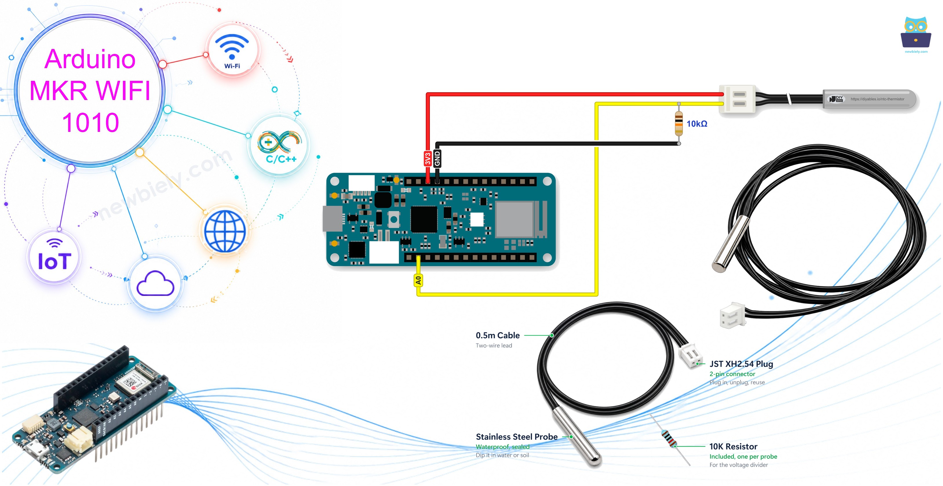
Hardware Preparation
| 1 | × | Arduino MKR WiFi 1010 | |
| 1 | × | Micro USB Cable | |
| 1 | × | 10K NTC Thermistor 3950 Waterproof Probe (with 10K resistor) | |
| 1 | × | Jumper Wires | |
| 1 | × | Optionally, Breadboard |
Or you can buy the following kits:
| 1 | × | DIYables Sensor Kit (18 sensors/displays) |
Additionally, some of these links are for products from our own brand, DIYables .
Overview of NTC Thermistor Temperature Sensor
Think of a thermistor as a resistor that cares about heat. Its value in ohms changes a lot when the temperature changes, and the MKR can measure that value and work out the degrees from it. The letters NTC mean Negative Temperature Coefficient. Put simply: warmer makes the resistance smaller, colder makes it bigger.
Here, the thermistor is sealed in the rounded end of a small stainless steel tube (5 x 25mm), so the tip may sit in water. Half a meter of black cable joins the tube to a white 2-hole JST XH2.54 connector. One pack gives you five probes plus five 10K resistors that match them, so the circuit needs no extra parts from the shop.
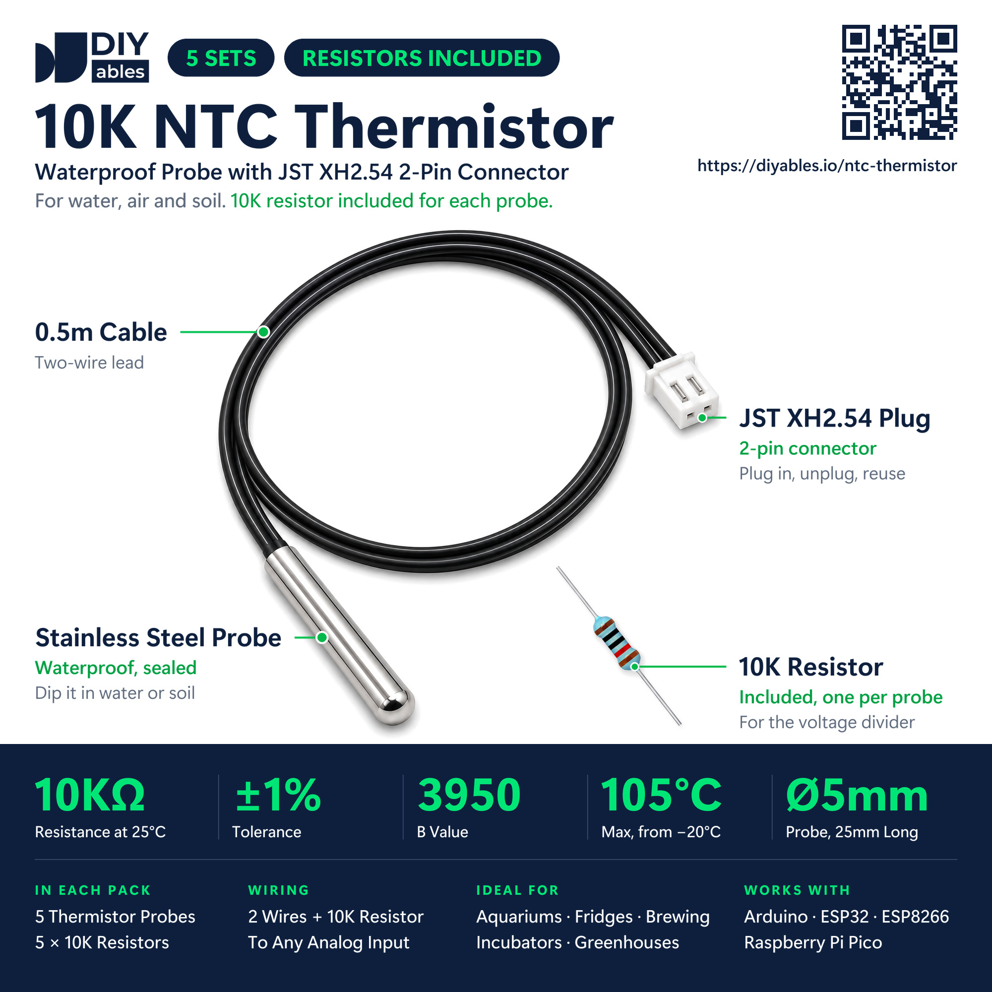
| 10K NTC 3950 Probe Kit | |
|---|---|
| Thermistor | NTC, 10kΩ ±1% at 25°C |
| B Constant | 3950 |
| Measuring Range | -20°C to +105°C |
| Probe Tip | stainless steel, waterproof, 5mm x 25mm, rounded end |
| Lead | 0.5m black two-core cable |
| Connector | JST XH2.54 (white), 2-pin |
| Insulation | over 100MΩ |
| In the Box | 5 probes, 5 x 10K resistors |
You will not find an adapter board or any pin labels here. The connector simply has two openings, and a male jumper wire slides into each one. Both wires are the same, since a thermistor, like every resistor, works in either direction:
- One probe wire (pick either): needs to be connected to the VCC pin of Arduino MKR WiFi 1010, which gives 3.3V
- The other probe wire: needs to be connected to A0, an analog input of the MKR
- The kit's 10K resistor: needs to be connected to A0 with one leg and to GND (0V) with the other leg
How the MKR Turns Ohms Into Degrees
The analog pins of the MKR measure a voltage, not a resistance. That is why the probe and its 10K partner are put in a row between 3.3V and GND, and A0 listens to the point in the middle. Two resistors used like this are called a voltage divider. A warm probe lets more current through, so A0 ends up with a bigger share of the 3.3V. A cold probe holds more of the voltage back, and A0 sees less. With a 12-bit reading, these are the numbers to expect:
| Temperature of the Tip | Probe Resistance | A0 Voltage | 12-bit analogRead() |
|---|---|---|---|
| -20°C | 105.4kΩ | 0.29V | 355 |
| 20°C | 12.5kΩ | 1.46V | 1817 |
| 37°C | 6.0kΩ | 2.06V | 2561 |
| 60°C | 2.5kΩ | 2.64V | 3280 |
| 80°C | 1.3kΩ | 2.93V | 3633 |
The sketch walks this table backwards. From the analogRead() number it finds the probe resistance R, and from R it finds the temperature T in kelvin with the B formula (also known as the beta equation):
1/T = 1/T0 + (1/B) × ln(R/R0)
This probe uses B = 3950, R0 = 10000Ω and T0 = 298.15K (the kelvin value of 25°C). Subtracting 273.15 from T turns kelvin into °C. Some people use the Steinhart-Hart equation, a 3-coefficient formula that is a little more exact. For this probe, the single B value does the job well. Around room temperature, being off by about 1°C is normal. The real value of your 10K resistor and the MKR's ADC decide the rest.
Why the VCC pin and not 5V? There are two reasons:
- The MKR WiFi 1010 is a 3.3V board, and an analog pin must never get more than 3.3V. With 5V on the divider, A0 would climb to about 4.4V once the probe reaches 80°C. That is too much for the SAMD21 chip.
- The ADC of the MKR measures against the same 3.3V supply that comes out of the VCC pin. Because the divider hangs on that same supply, only the ratio raw / 4095 counts. If the 3.3V is a little high or low, both sides move together, so the code never needs the exact voltage.
Where can the probe go? Anywhere a wet or closed space needs watching: an aquarium, a freezer or fridge, a fermentation bucket for home brew, an egg incubator, a greenhouse or a hydroponic tank. The MKR WiFi 1010 adds one more thing: it can later send the temperature over WiFi, so you can check it without walking over.
Wiring Diagram
Only three pins of the MKR take part: VCC, GND and A0. VCC and GND sit next to each other on one header row, while A0 is on the other row. That is why, in the picture, the A0 wire comes around from the opposite side of the board. The wire on VCC carries the tag 3V3, which is the voltage this pin gives out.
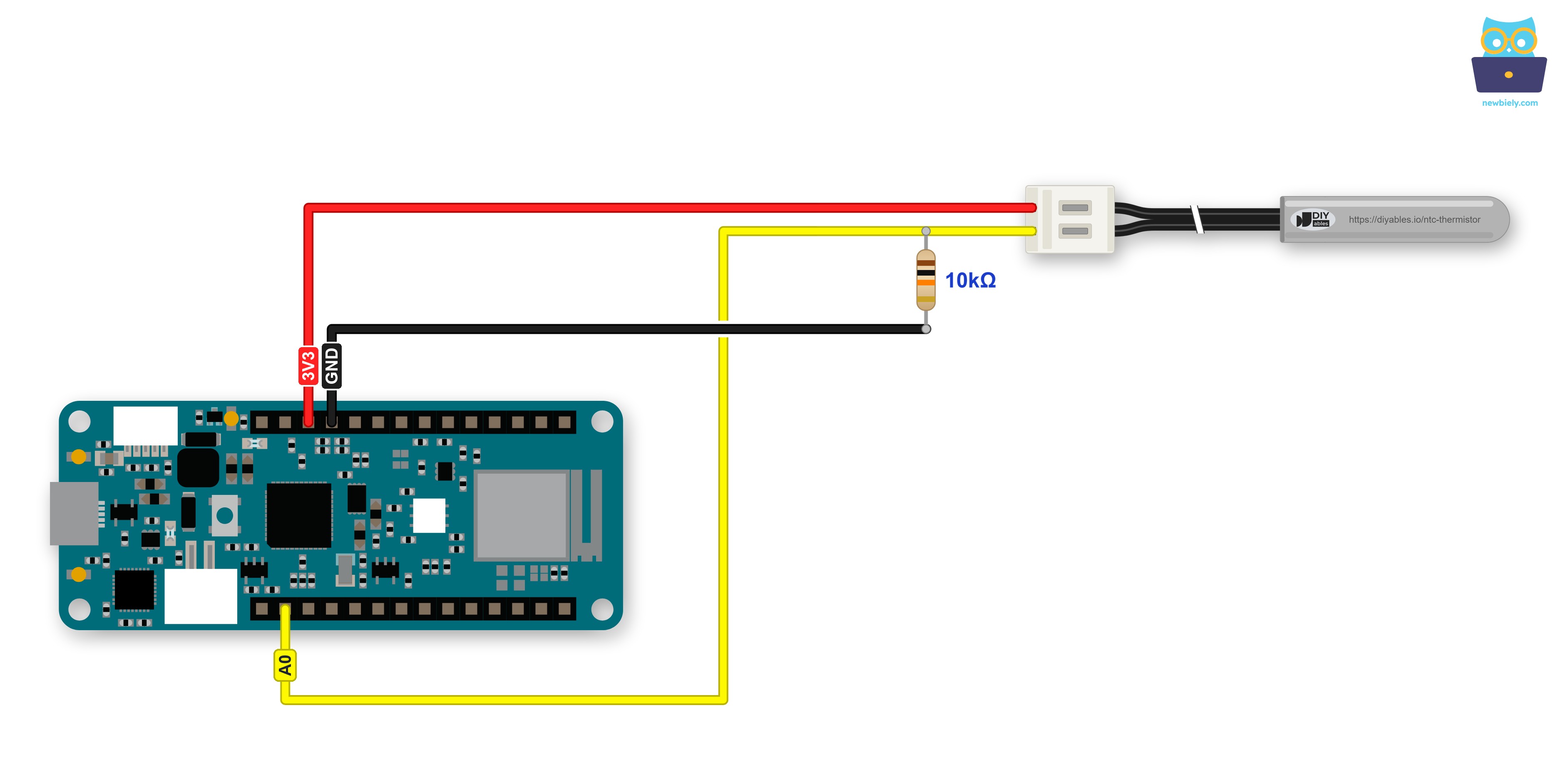
This image is created using Fritzing. Click to enlarge image
| Thermistor Circuit | Arduino MKR WiFi 1010 Pin |
|---|---|
| Probe wire, either one | VCC (3.3V) |
| Other probe wire | A0 |
| 10K resistor, one leg | A0 |
| 10K resistor, other leg | GND |
The picture puts the 10K resistor right between the yellow A0 wire and the black GND wire. On a desk, a small breadboard is the easiest way to make those joints: put the two resistor legs into two different rows, plug the second probe wire and the A0 jumper into the first row, and plug the GND jumper into the second row. No breadboard? Bend each resistor leg into a small hook around its jumper end and squeeze it closed, or solder the joints for a project that has to last.
Keep the probe wire on VCC. The 5V pin of the MKR is only for parts that really need 5V, and here it would push A0 over its 3.3V limit as the probe gets hot.
How To Program For NTC Thermistor
- Nothing to install: the Arduino core already has analogRead() and log().
- Give names to the pin and the probe numbers: const int NTC_PIN = A0;, const float SERIES_RESISTOR = 10000.0;, const float NTC_R25 = 10000.0;, const float NTC_T25 = 298.15; and const float NTC_BETA = 3950.0;
- Switch to 12 bits in setup(): analogReadResolution(12);. The MKR then counts from 0 up to 4095 (out of the box it stops at 1023), so one step is only about 0.8mV.
- Take ten readings and average them: sum += analogRead(NTC_PIN); inside a for loop, then float raw = sum / (float)SAMPLE_COUNT;. This keeps the last digit of the temperature calm.
- Look at the raw value before any math. Under 20 means there is no probe (the 10K resistor pulls A0 to 0V). Over 4075 means a short, or a resistor that is not on GND. Both would end in inf or nan, so a short warning is printed in place of the temperature.
- Work out the probe resistance: float ntcOhms = SERIES_RESISTOR * (ADC_FULL_SCALE / raw - 1.0);. This form is right because the probe is on the VCC side and the 10K resistor is on the GND side.
- Turn ohms into kelvin with the B formula, where log() means the natural log (ln): float kelvin = 1.0 / (1.0 / NTC_T25 + log(ntcOhms / NTC_R25) / NTC_BETA);
- Change kelvin into everyday units: celsius = kelvin - 273.15; and fahrenheit = celsius * 9.0 / 5.0 + 32.0;
- Let the Serial Monitor catch up: while (!Serial && millis() < 3000); comes after Serial.begin(9600);, because the MKR talks to the PC through its own native USB port.
Arduino Code - Temperature from the NTC Thermistor Probe
Every second, this sketch prints one line: the probe resistance in kilohms, the averaged raw number from A0, and the temperature in °C and °F. A missing or shorted probe gives a warning line instead.
Detailed Instructions
- Connect Arduino MKR WiFi 1010 to PC via Micro USB cable.
- Make the three connections from the wiring diagram. One probe wire goes on VCC, not on 5V.
- Navigate to the Arduino IDE, then select the Arduino MKR WiFi 1010 board and its port. Using this board for the first time? See Getting Started with Arduino MKR WiFi 1010 first.
- Copy the above code and paste it into Arduino IDE.
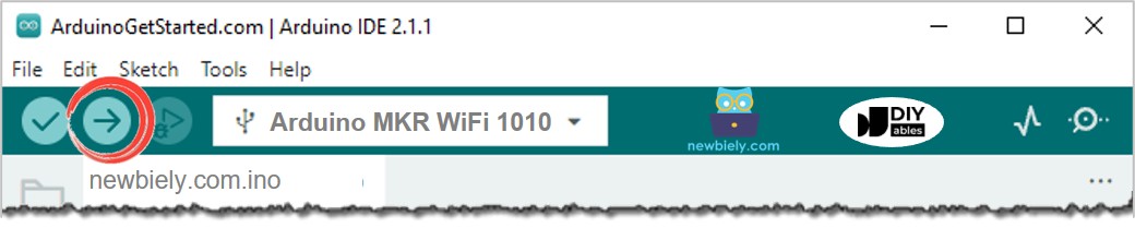
- Click the Upload button to send the code to Arduino MKR WiFi 1010.
- Open the Serial Monitor and pick 9600 baud.
- Let the probe rest on the desk while the first lines appear. Meanwhile, mix water from the kettle with tap water in a mug until it feels like a warm bath. Then dip the steel tip into the mug.
Lines one to four were taken in room air, close to 21°C. Once the tip was in the mug, the raw number shot up and the resistance dropped from about 12kΩ to 4.5kΩ. After some five seconds the reading stopped near 44°C, the temperature of the water. Lift the probe out and you will see the numbers slowly walk back down.
Something looks wrong?
- Warming the probe makes the number fall: thermistor and resistor sit in each other's places. The probe belongs between VCC and A0, the resistor between A0 and GND.
- You only see "No thermistor found": a jumper wire came loose from the white connector, or the A0 wire sits on another pin.
- The readings are steady but always a few degrees off: check that the resistor is the kit's 10K one and not some other value. A multimeter tells you for sure.
Tips for the waterproof probe:
- The steel tube is the only sealed part. Hold the connector, the jumpers and the resistor joints above the water line.
- Give the tip a few seconds at each new temperature. The steel needs a moment to warm up or cool down all the way through.
- Stay at 105°C or below. For hotter jobs such as a pizza oven, a thermocouple sensor like the MAX6675 module is the better tool.
What to try next: print the temperature on an LCD, or let a relay switch a fan or a heater at the temperature you choose. If you prefer a probe that does the math itself and sends a ready digital value, the waterproof DS18B20 is covered in Arduino MKR WiFi 1010 - Temperature Sensor.