Arduino Mega - 74HC595 4-Digit 7-Segment Display
Got an Arduino Mega and want to drive a 4-digit 7-segment display? The 74HC595-based display module is your quickest path from wiring to a working readout - and with the DIYables_4Digit7Segment_74HC595 library you can start writing code in minutes.
This step-by-step walkthrough covers:
Wiring the 74HC595 display to an Arduino Mega.
Showing integers, floats, and text on the display.
Displaying temperature with a degree symbol.
Showing time in HH.MM format with a blinking separator.
The Mega brings extra I/O, more SRAM, and additional hardware serial ports - handy when your project needs to talk to sensors alongside the display.
Or you can buy the following kits:
Disclosure: Some of the links provided in this section are Amazon affiliate links. We may receive a commission for any purchases made through these links at no additional cost to you.
Additionally, some of these links are for products from our own brand,
DIYables .
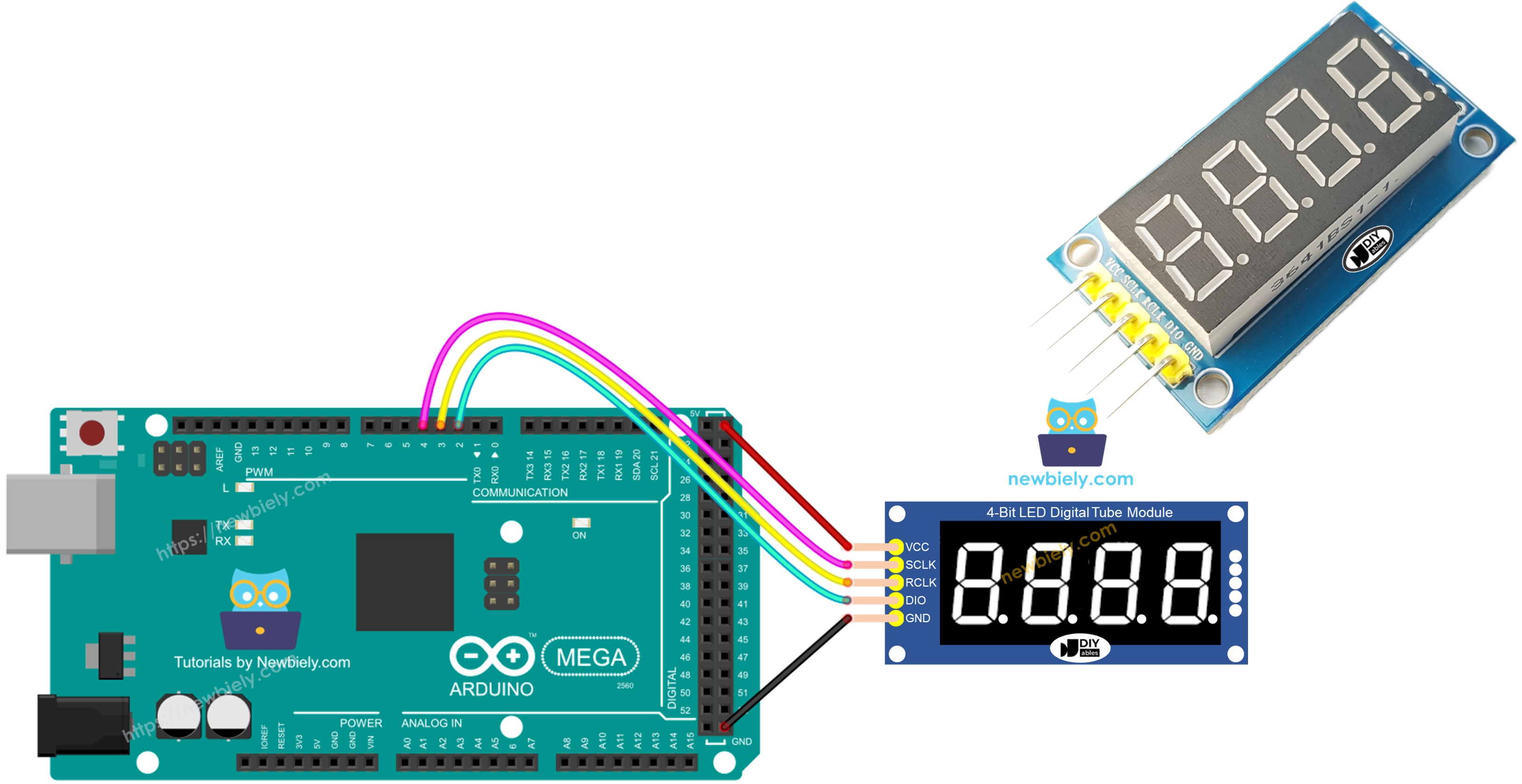
This display module combines four 7-segment digits with a 74HC595 shift register, letting you control all four digits and their decimal points through just 3 wires. The shift register takes serial data and converts it to parallel output for the segments.
The library handles the multiplexing (rapidly switching between digits) so you only need to call print() with the value you want to show.
| Function | Pin | Description |
|---|
| SCLK (SH_CP) | Serial Clock | Clocks data into the shift register |
| RCLK (ST_CP) | Register Clock | Latches data to the output |
| DIO (DS) | Data Input | Serial data line |
| VCC | Power | 3.3V or 5V |
| GND | Ground | Common ground |
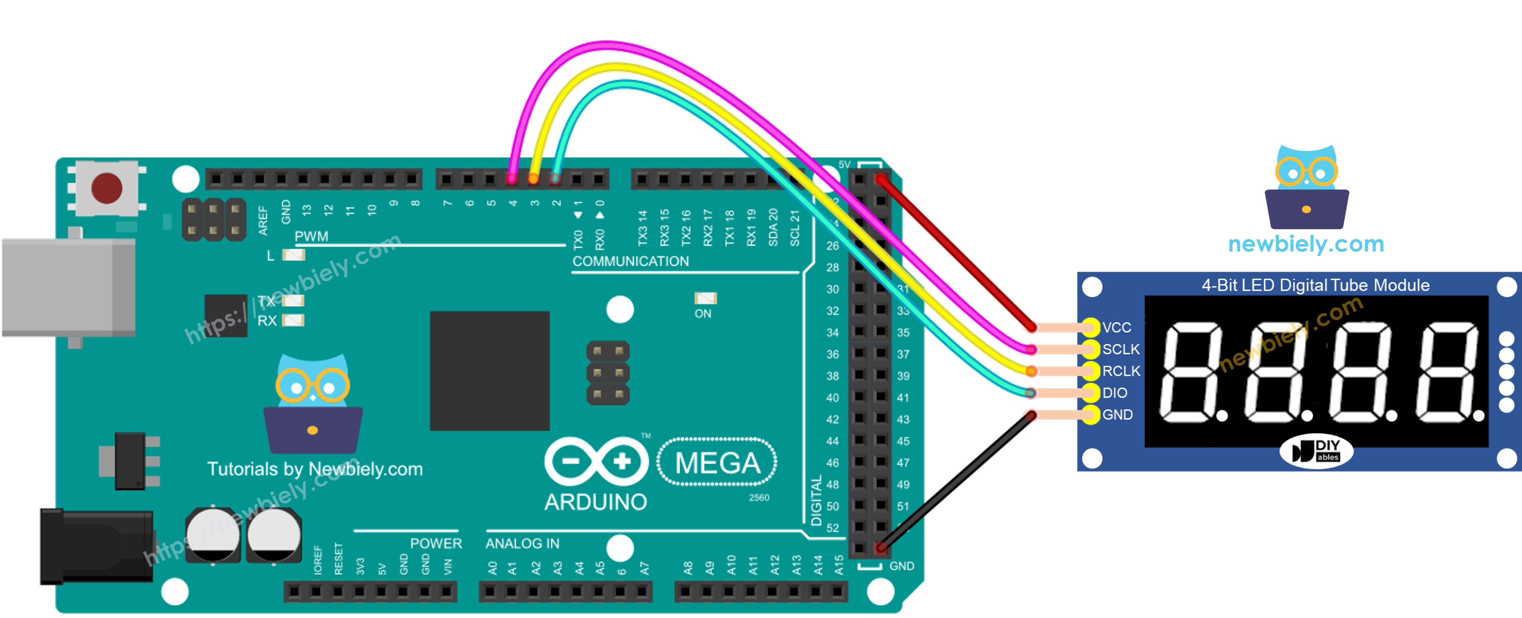
Hook up the display module to the Mega:
SCLK to pin 4
RCLK to pin 3
DIO to pin 2
VCC to 5V OR 3.3V
GND to GND
This image is created using Fritzing. Click to enlarge image
Connect your Arduino Mega to the computer via a USB cable.
Open the Arduino IDE. Pick Arduino Mega or Mega 2560 as the board and choose the correct port.
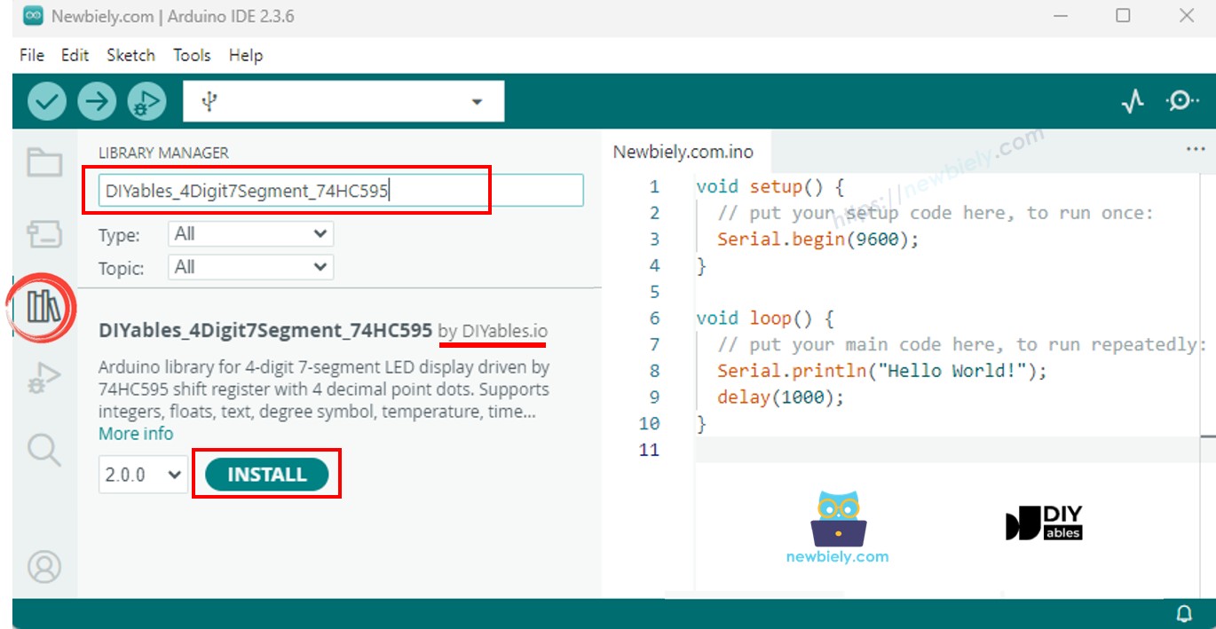
Go to the Libraries panel on the left side.
Search for "DIYables_4Digit7Segment_74HC595". Find the entry from DIYables.
Press Install. Select version 2.0.0 or later.
The library has zero external dependencies.
The bare minimum to get started:
#include <DIYables_4Digit7Segment_74HC595.h>
#define SCLK_PIN 4
#define RCLK_PIN 3
#define DIO_PIN 2
DIYables_4Digit7Segment_74HC595 display(SCLK_PIN, RCLK_PIN, DIO_PIN);
void setup() {
display.begin();
display.print(1234);
}
void loop() {
display.loop();
}
The begin() call sets up pin modes. After that, set the display value with print() and keep calling display.loop() so the multiplexing runs. If your code includes long waits, swap delay() for display.delay() to avoid blanking the display.
Cycles through a list of integers, then shows a zero-padded number.
#include <DIYables_4Digit7Segment_74HC595.h>
#define SCLK_PIN 4
#define RCLK_PIN 3
#define DIO_PIN 2
DIYables_4Digit7Segment_74HC595 display(SCLK_PIN, RCLK_PIN, DIO_PIN);
int numbers[] = {0, 42, 1234, -5, -123, 9999};
int numCount = 6;
int currentIndex = 0;
bool showZeroPad = false;
unsigned long lastChange = 0;
void setup() {
Serial.begin(9600);
display.begin();
Serial.println("4-Digit 7-Segment 74HC595 - Integer Example");
}
void loop() {
display.loop();
if (millis() - lastChange >= 2000) {
lastChange = millis();
if (!showZeroPad) {
display.print(numbers[currentIndex]);
Serial.print("Displaying: ");
Serial.println(numbers[currentIndex]);
currentIndex++;
if (currentIndex >= numCount) {
currentIndex = 0;
showZeroPad = true;
}
} else {
display.print(42, true);
Serial.println("Displaying: 0042 (zero-padded)");
showZeroPad = false;
}
}
}
Wire the display to the Mega as described above.
Plug in the USB cable.
Paste the code into Arduino IDE, select the board and port, and hit Upload.
Open the Serial Monitor (9600 baud) to watch the output.
The display runs through 0, 42, 1234, -5, -123, 9999, then 0042 with zero-padding.
| Method | Effect | Sample Call |
|---|
| print(int) | Show an integer | display.print(1234) |
| print(int, true) | Show integer with leading zeros | display.print(42, true) |
| loop() | Keep the display refreshing | display.loop() |
Shows floating-point numbers with auto and fixed decimal places.
#include <DIYables_4Digit7Segment_74HC595.h>
#define SCLK_PIN 4
#define RCLK_PIN 3
#define DIO_PIN 2
DIYables_4Digit7Segment_74HC595 display(SCLK_PIN, RCLK_PIN, DIO_PIN);
void setup() {
Serial.begin(9600);
display.begin();
Serial.println("4-Digit 7-Segment 74HC595 - Float Example");
}
void loop() {
display.print(1.5);
Serial.println("Auto decimal: 1.5");
display.delay(2000);
display.print(12.34);
Serial.println("Auto decimal: 12.34");
display.delay(2000);
display.print(3.141);
Serial.println("Auto decimal: 3.141");
display.delay(2000);
display.print(-1.2);
Serial.println("Auto decimal: -1.20");
display.delay(2000);
display.print(0.5);
Serial.println("Auto decimal: 0.5");
display.delay(2000);
display.print(23.5, 1);
Serial.println("1 decimal place: 23.5");
display.delay(2000);
display.print(1.5, 2);
Serial.println("2 decimal places: 1.50");
display.delay(2000);
display.print(1.5, 2, true);
Serial.println("2 decimal places, zero-padded: 01.50");
display.delay(2000);
}
Paste the code into Arduino IDE, select the board and port, and hit Upload.
Open the Serial Monitor to watch the output.
Various floats appear with auto decimals, then with 1 and 2 fixed places, and finally with zero-padding.
Displays text strings, degree symbols, and temperature readings.
#include <DIYables_4Digit7Segment_74HC595.h>
#define SCLK_PIN 4
#define RCLK_PIN 3
#define DIO_PIN 2
DIYables_4Digit7Segment_74HC595 display(SCLK_PIN, RCLK_PIN, DIO_PIN);
const char* texts[] = {"HELP", "Hi", "COOL", "done"};
int textCount = 4;
int currentIndex = 0;
int phase = 0;
unsigned long lastChange = 0;
void setup() {
Serial.begin(9600);
display.begin();
Serial.println("4-Digit 7-Segment 74HC595 - Text and Degree Example");
}
void loop() {
display.loop();
if (millis() - lastChange >= 2000) {
lastChange = millis();
if (phase == 0) {
display.print(texts[currentIndex]);
Serial.print("Text: ");
Serial.println(texts[currentIndex]);
currentIndex++;
if (currentIndex >= textCount) {
currentIndex = 0;
phase = 1;
}
} else if (phase == 1) {
display.printTemperature(25, 'C');
Serial.println("Temperature: 25 C");
phase = 2;
} else if (phase == 2) {
display.printTemperature(72, 'F');
Serial.println("Temperature: 72 F");
phase = 3;
} else if (phase == 3) {
char degStr[5];
degStr[0] = '2';
degStr[1] = '5';
degStr[2] = DEGREE_CHAR;
degStr[3] = 'C';
degStr[4] = '\0';
display.print(degStr);
Serial.println("String with degree: 25 deg C");
phase = 4;
} else {
display.print("1.2.3.4");
Serial.println("Dots: 1.2.3.4");
phase = 0;
}
}
}
Shows text like "HELP" and "COOL", then temperatures (25 degrees C, 72 degrees F), then inline dots.
Shows HH.MM format with a blinking separator dot.
#include <DIYables_4Digit7Segment_74HC595.h>
#define SCLK_PIN 4
#define RCLK_PIN 3
#define DIO_PIN 2
DIYables_4Digit7Segment_74HC595 display(SCLK_PIN, RCLK_PIN, DIO_PIN);
int hours = 12;
int minutes = 30;
bool colonOn = true;
unsigned long lastToggle = 0;
void setup() {
Serial.begin(9600);
display.begin();
Serial.println("4-Digit 7-Segment 74HC595 - Time Example");
Serial.println("Displaying 12:30 with blinking dot separator");
}
void loop() {
display.loop();
if (millis() - lastToggle >= 500) {
lastToggle = millis();
display.printTime(hours, minutes, colonOn);
colonOn = !colonOn;
}
}
Displays 12.30 with the dot toggling every half second.
Blinks integers, floats, and text using off() and on().
#include <DIYables_4Digit7Segment_74HC595.h>
#define SCLK_PIN 4
#define RCLK_PIN 3
#define DIO_PIN 2
DIYables_4Digit7Segment_74HC595 display(SCLK_PIN, RCLK_PIN, DIO_PIN);
int phase = 0;
int blinkCount = 0;
bool isOn = true;
unsigned long lastAction = 0;
unsigned long pauseUntil = 0;
void setup() {
Serial.begin(9600);
display.begin();
Serial.println("4-Digit 7-Segment 74HC595 - Blink Example");
display.print(1234);
Serial.println("Blinking: 1234");
}
void loop() {
display.loop();
unsigned long now = millis();
if (now < pauseUntil) return;
if (now - lastAction >= 300) {
lastAction = now;
if (isOn) {
display.off();
isOn = false;
} else {
display.on();
isOn = true;
blinkCount++;
if (blinkCount >= 5) {
blinkCount = 0;
pauseUntil = now + 1000;
phase++;
if (phase > 2) phase = 0;
switch (phase) {
case 0:
display.print(1234);
Serial.println("Blinking: 1234");
break;
case 1:
display.print(12.34);
Serial.println("Blinking: 12.34");
break;
case 2:
display.print("HELP");
Serial.println("Blinking: HELP");
break;
}
}
}
}
}
The display blinks 1234 five times, then 12.34, then "HELP".
| Symptom | Likely Cause | Fix |
|---|
| Nothing on display | Wiring or pin mismatch | Check VCC/GND and that SCLK, RCLK, DIO pins match your code |
| Wrong characters | Common anode/cathode mismatch | Use false as 4th constructor arg for common cathode |
| Flickering or blank | delay() blocking refresh | Replace delay() with display.delay() |
Built entirely on Arduino standard APIs - compatible with every Arduino-supported architecture.