Arduino Mega - Relay
This guide shows you how to use an Arduino Mega and a relay to turn high-voltage devices on and off. These devices include light bulbs, fans, electric locks, and linear actuators. Here’s what we will learn:
- What a relay does
- How to hook the relay up to a high-voltage device
- How to connect the Arduino Mega to the relay
- How to program the Arduino Mega to control the relay and turn high-voltage devices on and off
Hardware Preparation
Or you can buy the following kits:
| 1 | × | DIYables Sensor Kit (18 sensors/displays) |
Additionally, some of these links are for products from our own brand, DIYables .
Overview of Relay
A relay is a switch you can program. It is controlled by devices like Arduino Mega or other small computers. It lets you turn things on or off automatically, especially things that use a lot of power or high voltage.
A relay is a link between an Arduino Mega and high-voltage devices.
WARNING
When you work with power from the mains, you need to know what you’re doing to avoid getting an electric shock. Safety is very important. If you’re not sure about what you’re doing, don’t try to handle anything. Instead, ask for help from someone who has experience. We recommend using a DC device (up to 24V) for testing, even though some relays can work with both DC and AC.
Relay Pinout
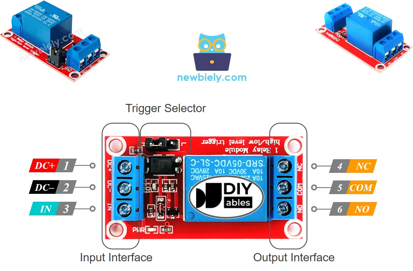
A relay has two groups of pins: the input pins use low voltage, and the output pins use high voltage.
- Input pins connect to the Arduino Mega. There are three pins:
- DC- pin: connect to ground (0V).
- DC+ pin: connect to +5V (VCC).
- IN pin: receives the control signal from the Arduino Mega.
- Output pins connect to the high-voltage device. There are three pins (usually in a screw terminal):
- COM pin: the common pin used in both normally open and normally closed modes.
- NO pin: the normally open pin. Used in normally open mode.
- NC pin: the normally closed pin. Used in normally closed mode.
- In normally open mode, only the COM and NO pins are used.
- In normally closed mode, only the COM and NC pins are used.
- Low-level trigger mode
- High-level trigger mode
- Default open mode
- Default closed mode
- Normally open and normally closed modes work in opposite ways.
- Most relay modules support both normally open and normally closed modes.
- Low-level trigger and high-level trigger modes work in opposite ways.
- Not every relay module supports both low-level trigger and high-level trigger modes.
- At any time, the relay module can operate in only one mode, either low-level trigger or high-level trigger.
- If the input pin is low (0 volts), the switch is open and the device is off.
- If the input pin is high (5 volts), the switch is closed and the device is on.
- When the input is at low (0 V), the switch is closed. The device is ON.
- When the input is at high (5 V), the switch is open. The device is OFF.
- Connect the Arduino Mega pin to the relay's IN pin.
- Set the pin to LOW or HIGH to turn the relay on or off.
Usually we don't use all the pins in the high-voltage group. We only use two of them.
Also, if the relay can use both low-level and high-level triggers, there is usually a small jumper to choose between them.
※ NOTE THAT:
Relays from different makers may place the pins in different orders. Always check the labels on the relay and connect it the right way. Look carefully!
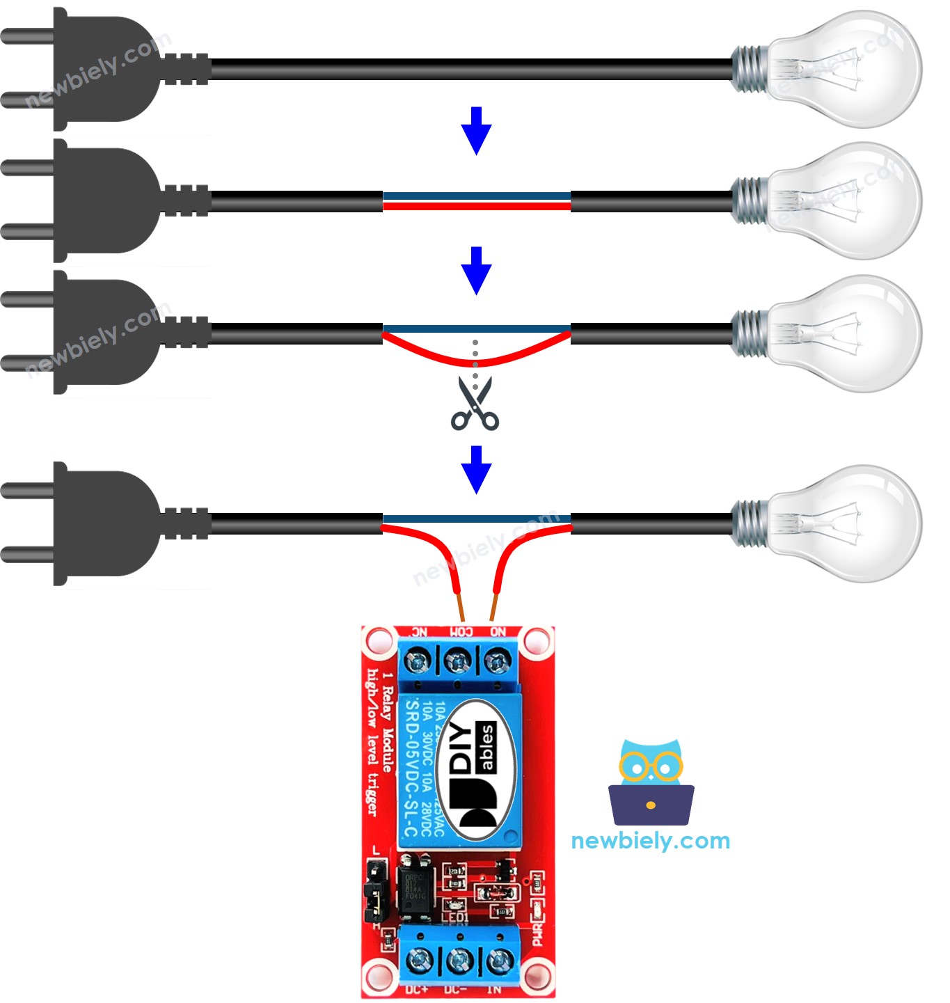
How to Connect the High Voltage Device to Relay
How It Works
A relay can work in different ways, depending on who makes it and how you install it.
The input mode: There are two input modes that make the relay work in opposite ways.
Output mode: There are two modes that make the relay work in opposite ways.
The word "normally" means the situation when the IN pin is connected to LOW (0V). Let's start with some quick information:
Using input modes and output modes gives many uses. For beginners, we recommend choosing high-level trigger mode and normally open mode.
The low level trigger and high level trigger modes work in different ways. Next, we will explain the high level trigger mode in detail. The low level trigger works in the opposite way.
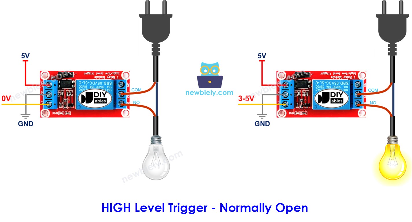
HIGH Level Trigger - Normally Open Mode
To enable this mode, connect the high voltage device to both the COM and NO pins.
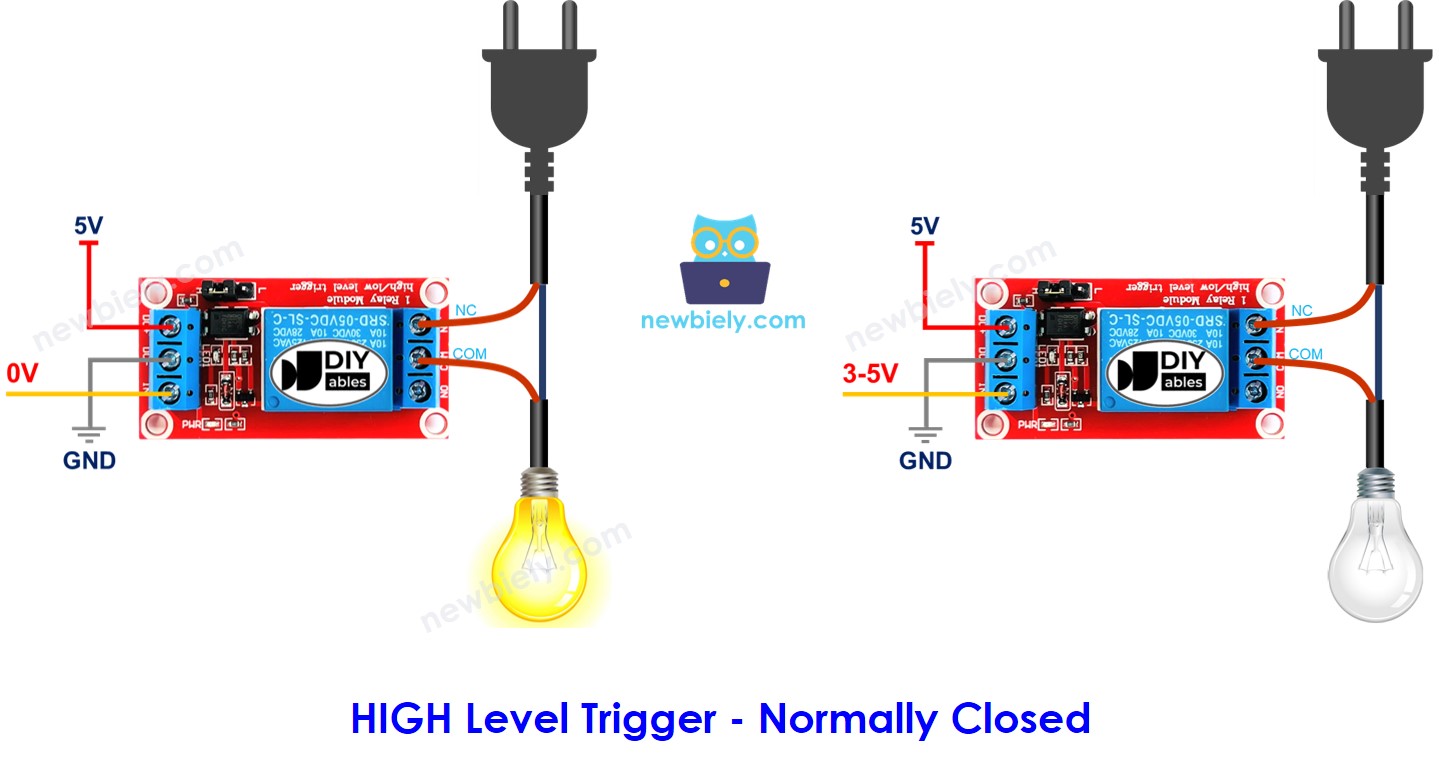
HIGH Level Trigger - Normally Closed Mode
To use this mode, connect the high-voltage device to the COM and NC pins.
Summary
| Input modes | Output Modes | IN pin (programmable) | Output pins | Relay state | Device state |
|---|---|---|---|---|---|
| HIGH Trigger | Normally Open | LOW | COM and NO pin | ⇒ open | ⇒ OFF |
| HIGH Trigger | Normally Open | HIGH | COM and NO pin | ⇒ closed | ⇒ ON |
| HIGH Trigger | Normally Closed | LOW | COM and NC pin | ⇒ closed | ⇒ ON |
| HIGH Trigger | Normally Closed | HIGH | COM and NC pin | ⇒ open | ⇒ OFF |
| LOW Trigger | Normally Open | LOW | COM and NO pin | ⇒ closed | ⇒ ON |
| LOW Trigger | Normally Open | HIGH | COM and NO pin | ⇒ open | ⇒ OFF |
| LOW Trigger | Normally Closed | LOW | COM and NC pin | ⇒ open | ⇒ OFF |
| LOW Trigger | Normally Closed | HIGH | COM and NC pin | ⇒ closed | ⇒ ON |
There can be as many as eight use cases. This may seem like a lot. But if you are a beginner, you only need to focus on the first two cases. These involve the high-level trigger and normally open settings. This tutorial mainly covers these two cases.
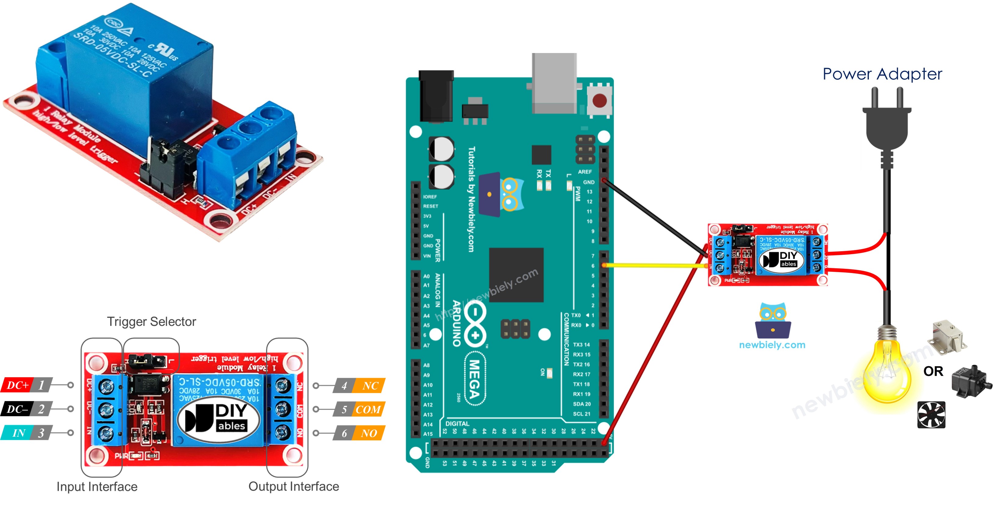
Arduino Mega - Relay
The Arduino Mega uses a relay to control a device that runs on high voltage.
It is easy to control a relay. We only need:
Wiring Diagram
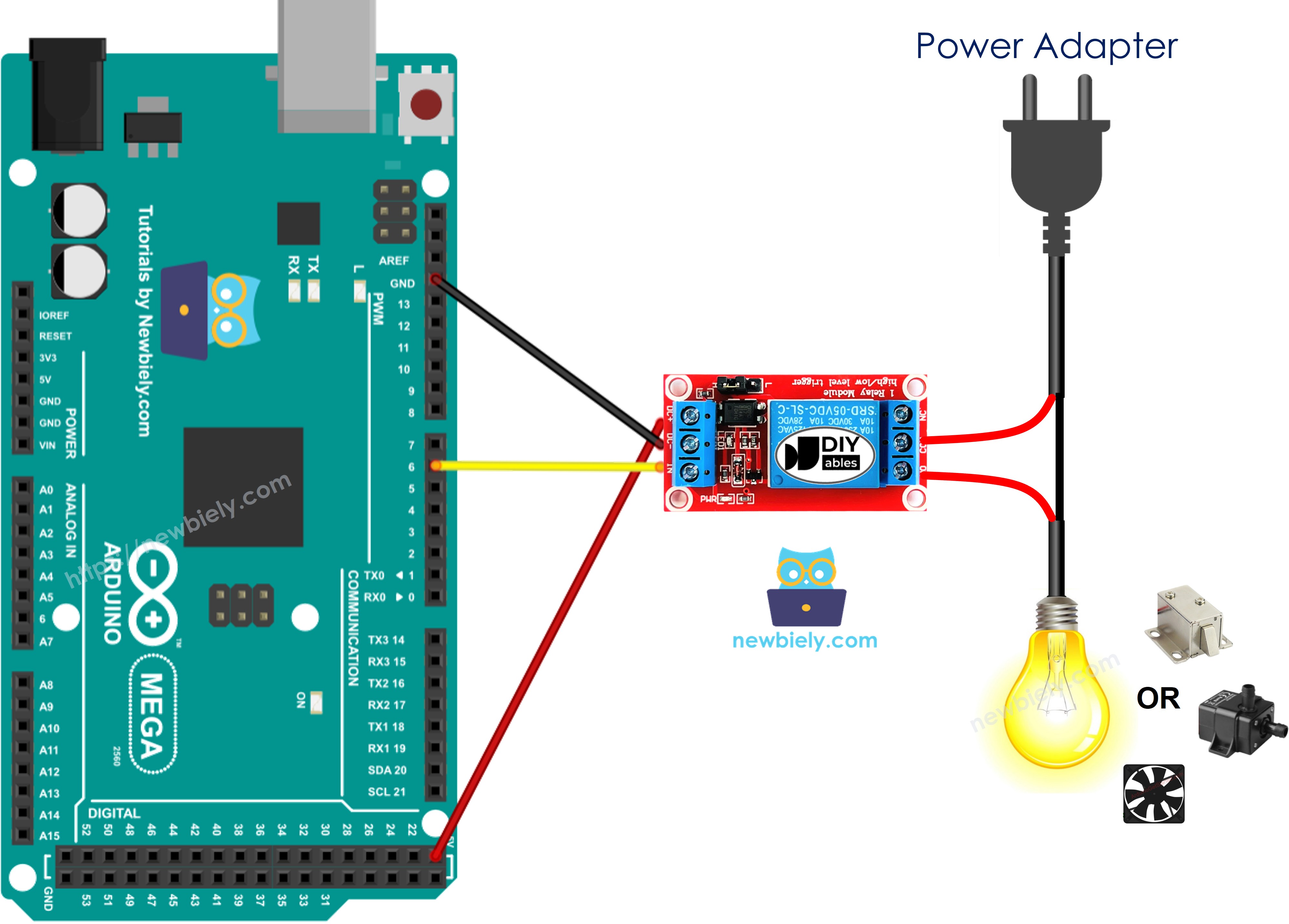
This image is created using Fritzing. Click to enlarge image
How To Program For Relay
- Set a pin on the Arduino Mega as an output using the pinMode() function. For example, pin 3:
- Set the pin to low (0 volts) using the digitalWrite() function.
- Set the pin to 5V using the digitalWrite() function.
Arduino Mega Code
Detailed Instructions
Follow these steps one by one.
- Connect the parts following the diagram.
- Connect the Arduino Mega board to your computer with a USB cable.
- Open the Arduino IDE on your computer.
- Choose the correct board (Arduino Mega) and the COM port.
- Copy the code and paste it into the Arduino IDE.
- Click the Upload button in the Arduino IDE to send the code to the Arduino Mega.
- Check the LED strip; it should blink.