Arduino Mega - LCD 20x4
Welcome to this comprehensive Arduino Mega LCD 20x4 tutorial! In this detailed Arduino Mega LCD 20x4 I2C guide, you'll discover how to harness the power of large-format 20-column by 4-row character displays with I2C communication for creating professional, information-rich interfaces in your Arduino Mega projects.
The LCD 20x4 I2C display is a significant upgrade from the standard 16x2 display, offering 80 characters of display space (compared to just 32). This makes it perfect for applications requiring more detailed information, multi-line menus, comprehensive status displays, or richer user interfaces. The "I2C" (Inter-Integrated Circuit) interface means you only need 2 communication wires (SDA and SCL) plus power connections, leaving your Arduino Mega pins free for sensors, actuators, and other components.
Throughout this Arduino Mega LCD 20x4 I2C tutorial, we'll explore everything you need to master large-format LCD displays:
- Understanding the advantages of 20x4 LCD I2C displays and their use cases
- Step-by-step instructions for properly connecting a 20x4 LCD I2C to your Arduino Mega microcontroller
- Programming techniques for displaying text, numbers, and data across 4 rows and 20 columns
- Working with the coordinate system for precise multi-line text layouts
- Creating organized information displays with proper spacing and alignment
- Managing power requirements for larger displays
This Arduino Mega LCD 20x4 display project opens up professional possibilities! Create multi-parameter sensor dashboards, scrolling information displays, detailed system status monitors, user navigation menus, multi-line message displays, real-time data loggers with timestamps, weather stations with comprehensive readouts, and any application where expanded visual feedback enhances functionality. The 20x4 LCD I2C is the choice for projects demanding more screen real estate!
Hardware Preparation
Or you can buy the following kits:
| 1 | × | DIYables Sensor Kit (18 sensors/displays) |
Additionally, some of these links are for products from our own brand, DIYables .
Buy Note: Alternatively, you can assemble the LCD I2C display using LCD 1602 Display and PCF8574 I2C Adapter Module.
Overview of LCD I2C 20x4
The 20x4 LCD I2C is a large-format character-based liquid crystal display module that combines a spacious 20-column by 4-row LCD screen with an integrated I2C interface adapter (typically a PCF8574 chip). This professional-grade display provides 2.5 times more display area than the popular 16x2 LCD, making it ideal for information-dense applications.
Key Features:
- Display Capacity: 80 characters total (20 columns × 4 rows) - perfect for detailed displays
- Character Size: Each character is formed by a 5×8 pixel matrix for excellent readability
- I2C Communication: Uses only 2 wires (SDA/SCL) despite the larger display size
- Adjustable Contrast: Built-in potentiometer on the back for contrast adjustment
- Backlight Control: Blue or green LED backlight (software-controllable via I2C)
- Low Pin Count: Only requires 4 total pins (VCC, GND, SDA, SCL)
- Larger Viewing Area: Typically measures 98mm × 60mm display area
Why Choose 20x4 Over 16x2?
The 20x4 LCD offers significant advantages for complex projects:
- More Information: Display 80 characters vs. 32 on a 16x2
- Better Organization: Four rows allow logical separation of different data types
- Menu Systems: Create multi-option menus without scrolling
- Status Displays: Show multiple sensor readings simultaneously
- Professional Appearance: More polished look for finished projects
- Same I2C Interface: No additional wiring complexity compared to smaller displays
I2C Advantages:
The I2C interface remains a massive benefit even with this larger display. It saves 10+ Arduino pins, allows multiple I2C devices on the same bus, simplifies wiring with just 4 connections, and maintains compatibility with standard I2C libraries. The larger display requires the same minimal connections as smaller LCDs!
Pinout
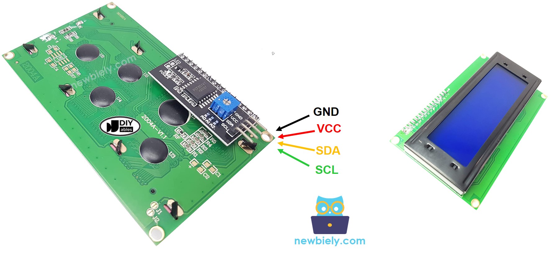
The LCD 20x4 I2C module features the same simple 4-pin interface as smaller I2C displays. Understanding these connections is essential for proper operation:
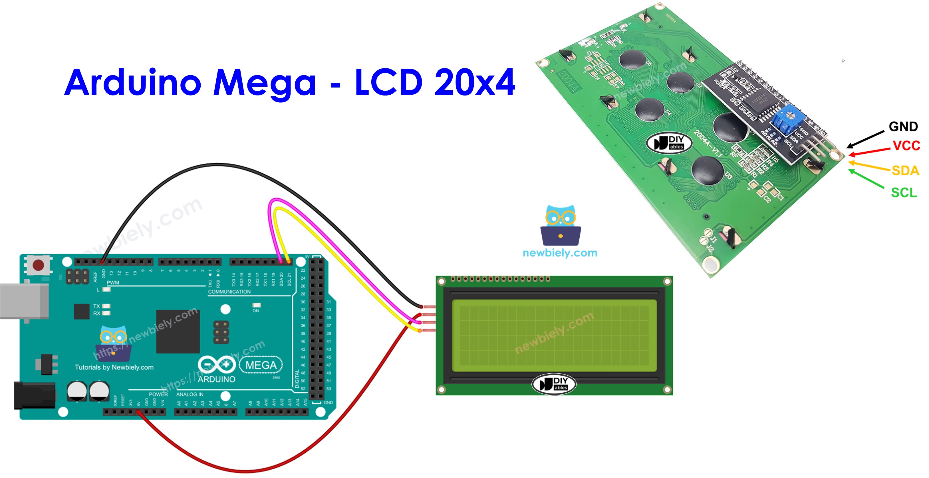
- GND pin: The ground reference pin. Connect this to the Arduino Mega's GND (0V) to complete the power circuit and establish a common ground reference.
- VCC pin: The power supply pin. Connect this to the Arduino Mega's 5V output to provide operating voltage. Note: The 20x4 LCD draws more current than smaller displays (typically 120-180mA with backlight on) due to its larger size and more LEDs.
- SDA pin: The Serial Data line for I2C communication. This bidirectional pin carries data between the Arduino Mega and the LCD module. Connect to the Arduino Mega's SDA pin (Digital Pin 20).
- SCL pin: The Serial Clock line for I2C communication. This pin carries the clock signal that synchronizes data transmission. Connect to the Arduino Mega's SCL pin (Digital Pin 21).
Power Considerations for 20x4 Displays:
The larger 20x4 LCD requires more power than smaller displays. With the backlight on, it can draw 120-180mA (compared to 20-40mA for a 16x2 display). When powered via USB, the Arduino Mega can typically supply enough current, but if you notice dim display or instability, consider:
- Using a powered USB hub instead of direct computer connection
- Adding an external 5V power supply for the LCD
- Reducing backlight brightness if the display supports PWM control
I2C Bus Note: The I2C bus supports multiple devices on the same two wires (SDA/SCL). Each device has a unique I2C address (typically 0x27 or 0x3F for LCD modules). The Arduino Mega's dedicated I2C pins (20 and 21) can reliably communicate with multiple I2C devices simultaneously.
Contrast Adjustment: On the back of the I2C adapter board, you'll find a small blue potentiometer. Use a small screwdriver to turn this pot clockwise or counterclockwise to adjust the LCD contrast for optimal readability. Proper contrast adjustment is especially important on larger displays!
LCD Coordinate System
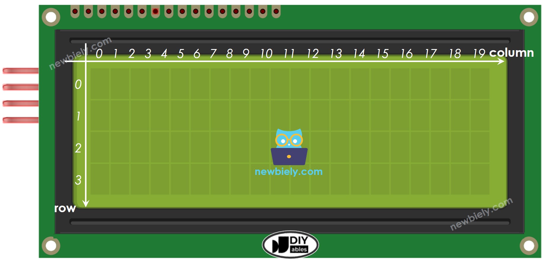
Understanding the LCD's coordinate system is crucial for creating well-organized multi-line displays. The 20x4 LCD I2C uses a zero-indexed grid coordinate system where both columns and rows start counting from 0 (not 1).
Coordinate Structure:
- Columns: Range from 0 to 19 (20 total positions horizontally)
- Rows: Range from 0 to 3 (4 total lines vertically)
- Format: lcd.setCursor(column, row) where column comes first
- Total Capacity: 80 character positions available
Key Position Examples:
- Top-left corner: (0, 0) - First column, first row
- Top-right corner: (19, 0) - Last column, first row
- Bottom-left corner: (0, 3) - First column, fourth row
- Bottom-right corner: (19, 3) - Last column, fourth row
- Center of display: (9, 1) or (10, 1) - Middle of second row
Practical Layout Tips:
Centering Text: For a 10-character string on 20-column display, start at column (20-10)/2 = 5
Organized Information Display:
Menu Layout Example:
Multi-Parameter Dashboard:
Cursor Behavior Notes:
- Text automatically wraps: if you print more than 20 characters starting at (0,0), it continues on row 1
- Cursor position persists: once set, subsequent lcd.print() calls continue from that position
- Use setCursor() before each print() statement for precise positioning
Wiring Diagram
Let's examine the straightforward wiring between your Arduino Mega and the LCD 20x4 I2C module. Despite the larger display size, the I2C interface keeps wiring simple with only 4 connections!
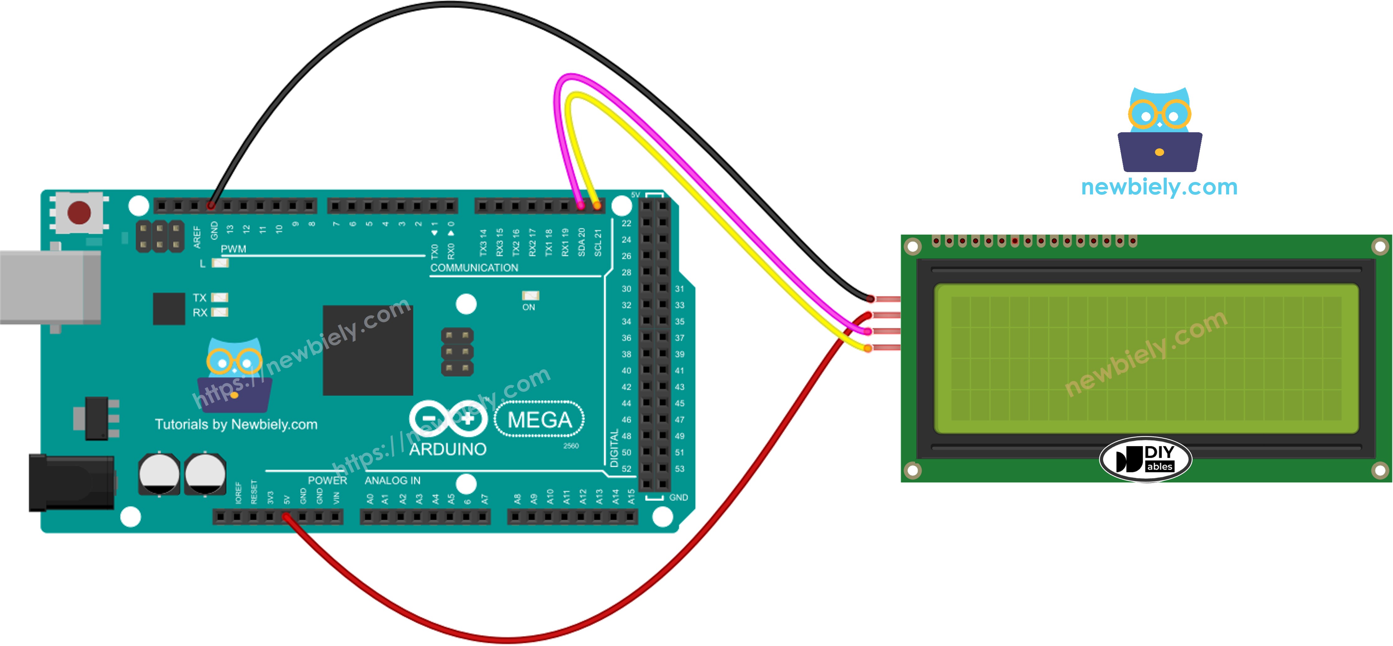
This image is created using Fritzing. Click to enlarge image
Connection Summary for Arduino Mega:
| LCD I2C | Arduino Uno, Nano | Arduino Mega |
|---|---|---|
| Vin | 5V | 5V |
| GND | GND | GND |
| SDA | A4 | 20 |
| SCL | A5 | 21 |
Important Pin Differences:
The Arduino Mega uses different I2C pins than smaller Arduino boards! While the Arduino Uno and Nano use pins A4 (SDA) and A5 (SCL), the Arduino Mega uses pins 20 (SDA) and 21 (SCL). Always verify you're connecting to the correct pins for your specific board.
Wiring Best Practices for 20x4 Displays:
- Use Quality Wires: Short jumper wires (under 30cm) provide the most reliable I2C communication
- Minimize Interference: Keep SDA and SCL wires away from noisy power lines and motors
- Power Considerations: The 20x4 LCD draws 120-180mA with backlight - ensure your power source can handle this
- External Power Option: If the display is dim or unstable, connect VCC to an external 5V supply instead of Arduino 5V pin
- Long Wire Runs: If using wires longer than 1 meter, add 4.7kΩ pull-up resistors on SDA and SCL lines
- Ground Connection: Always ensure solid GND connection between LCD and Arduino
Power Supply Recommendations:
- USB Power: Most computers provide 500mA via USB, sufficient for Arduino + LCD 20x4
- External Supply: Use a quality 5V 1A power adapter for projects with multiple components
- Shared Ground: When using external power for LCD, connect all grounds together (Arduino GND + LCD GND + Power Supply GND)
How To Program For LCD I2C
Let's explore the programming techniques for controlling your LCD 20x4 I2C display. The DIYables_LCD_I2C library makes it simple to work with large-format displays, handling all the I2C communication complexity behind the scenes.
Including the Library
First, include the DIYables_LCD_I2C library at the top of your sketch:
This library provides all the functions needed to communicate with I2C-based LCD displays of any size.
Creating the LCD Object
Create a DIYables_LCD_I2C object by specifying three parameters: the I2C address, number of columns, and number of rows. For the 20x4 display, use 20 columns and 4 rows:
I2C Address: Most LCD I2C modules use address 0x27 or 0x3F. If your LCD doesn't work with 0x27, try 0x3F. You can also scan for I2C devices using an I2C scanner sketch to find the correct address (see the LCD 16x2 tutorial for scanner code).
Initializing the LCD
In your setup() function, initialize the LCD and enable the backlight:
The init() function prepares the LCD for operation, configuring it for 20 columns and 4 rows. The backlight() function illuminates the display. You can use lcd.noBacklight() to turn it off later if needed to save power.
Positioning the Cursor
Before displaying text, set the cursor position using column and row coordinates:
Remember: columns range from 0-19, rows range from 0-3. The cursor determines where the next character will be printed.
Displaying Text
Use the print() function to display text or numbers on the LCD:
The print() function works just like Serial.print(), accepting strings, integers, floats, and other data types.
Creating Multi-Line Displays
With 4 rows available, organize your information logically:
Clearing Specific Rows
To update just one row without flickering the entire display, print spaces over the old content:
※ NOTE THAT:
I2C Address Note: Different brands use different I2C addresses for LCD modules. In our example, we used 0x27, the standard address for DIYables LCD modules. If you have a different brand, you may need to use 0x3F or run an I2C scanner to detect the address.
Arduino Mega Code
Detailed Instructions
Follow these detailed step-by-step instructions to get your LCD 20x4 I2C display working with your Arduino Mega:
1. Physical Connections: Wire the LCD 20x4 I2C display to the Arduino Mega following the wiring diagram shown above. Double-check all four connections: VCC to 5V, GND to GND, SDA to pin 20, and SCL to pin 21. Ensure connections are secure.
2. USB Connection: Connect the Arduino Mega board to your computer using a USB cable. Wait for your operating system to recognize the board and install any necessary drivers. Use a quality USB cable for reliable power delivery.
3. Open Arduino IDE: Launch the Arduino IDE software on your computer. If you haven't installed it yet, download it from the official Arduino website (arduino.cc).
4. Board Selection: In the Arduino IDE, navigate to Tools → Board and select "Arduino Mega or Mega 2560" from the list of available boards.
5. Port Selection: Go to Tools → Port and choose the COM port (Windows) or /dev/ttyUSB or /dev/ttyACM port (Mac/Linux) that corresponds to your connected Arduino Mega.
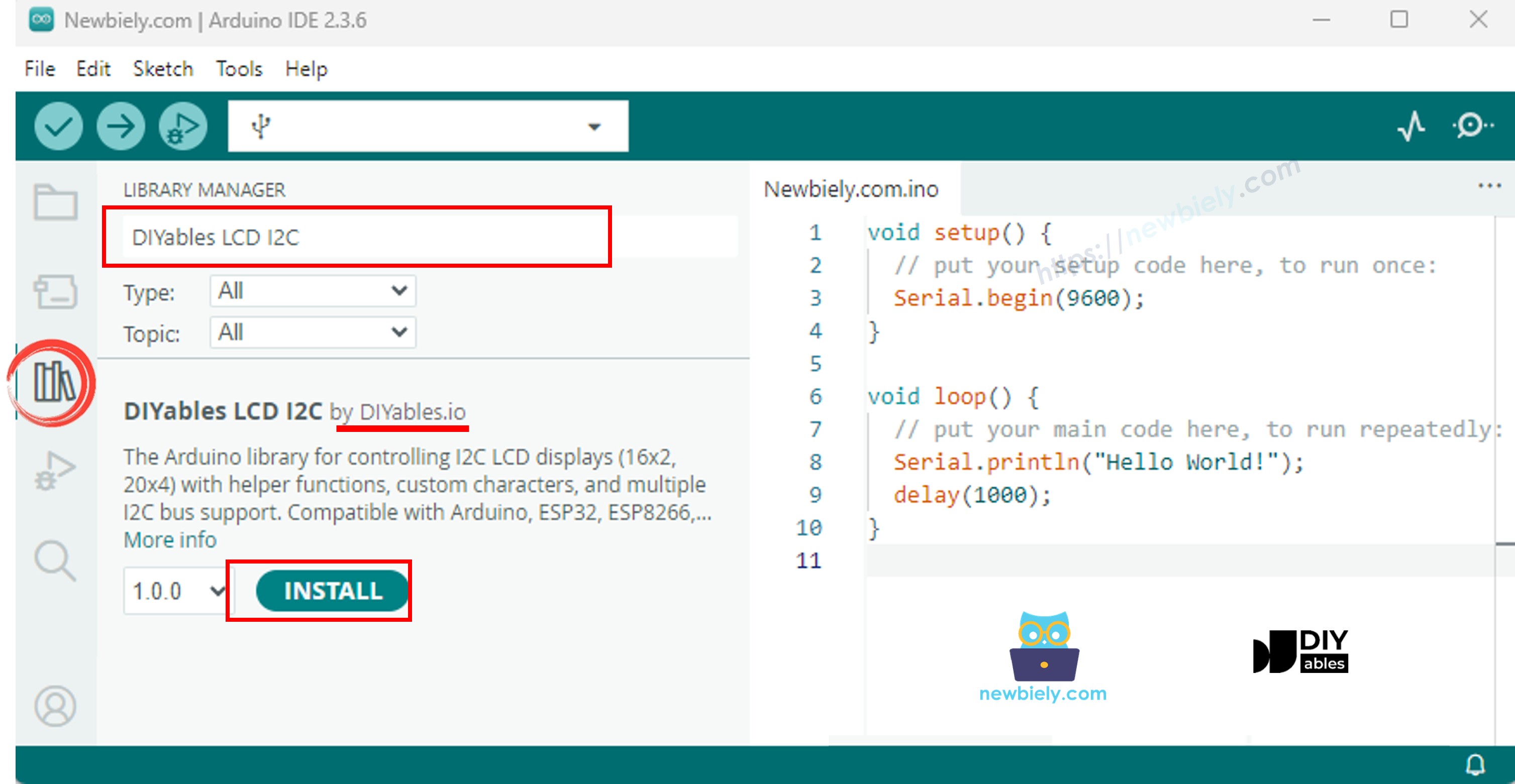
6. Library Installation: Click the Libraries icon (book icon) on the left sidebar of the Arduino IDE. In the search box, type "DIYables LCD I2C" and locate the DIYables_LCD_I2C library by DIYables.
7. Install Library: Click the Install button to add the DIYables_LCD_I2C library to your Arduino IDE. Wait for the installation to complete successfully.
8. Upload Code: Copy the example code provided above and paste it into a new Arduino IDE sketch. Click the Upload button (right arrow icon) in the toolbar to compile and upload the code to your Arduino Mega.
9. Verify Output: Look at the LCD screen. You should see:
- Row 0: "LCD 20x4"
- Row 1: "I2C Address: 0x27"
- Row 2: "DIYables"
- Row 3: "www.diyables.io"
10. Adjust Contrast (if needed): If you can't see the text clearly or at all, use a small screwdriver to carefully turn the blue potentiometer on the back of the I2C adapter board clockwise or counterclockwise until the text becomes clearly visible.
11. Check Power (if display is dim): The 20x4 LCD draws 120-180mA with backlight on. If the display appears dim or unstable:
- Try a different USB port or powered USB hub
- Use an external 5V power supply connected to LCD VCC and GND
- Ensure all ground connections are secure
Experiment Further: Try modifying the text strings and cursor positions in the code to create your own custom multi-line displays. Experiment with different layouts for sensor data, menus, or status information!