Arduino Mega - GPS
Welcome to this comprehensive Arduino Mega GPS tutorial where we'll explore the fascinating world of GPS technology integrated with the Arduino Mega microcontroller! In this detailed Arduino Mega GPS module guide, you'll discover how to harness the power of the NEO-6M GPS module to pinpoint your exact location anywhere on Earth using Arduino Mega.
Throughout this Arduino Mega GPS tutorial, we'll dive deep into reading critical GPS data from your GPS module including longitude (your east-west position), latitude (your north-south position), and altitude (your precise elevation above sea level). Beyond just GPS location data, you'll also learn to extract GPS-derived speed measurements (conveniently calculated in kilometers per hour) and access accurate date and time information directly from GPS satellites using your Arduino Mega and GPS module.
But that's not all! We'll take things a step further by teaching you how to perform GPS distance calculations between your current GPS position and any other coordinates on the planet with Arduino Mega. As a practical Arduino GPS example, we'll demonstrate calculating the distance from your location to the iconic city of London. This Arduino Mega GPS module project opens up endless possibilities for GPS navigation projects, location tracking systems, and GPS-based location applications.
Hardware Preparation
Or you can buy the following kits:
| 1 | × | DIYables Sensor Kit (18 sensors/displays) |
Additionally, some of these links are for products from our own brand, DIYables .
The Arduino Mega serves as the brain of your project, processing all GPS data received from the module. The USB cable provides both power and programming capabilities, while the jumper wires establish the vital serial communication link between your microcontroller and the GPS receiver.
Overview of NEO-6M GPS module
The NEO-6M is a compact, high-performance GPS (Global Positioning System) module that receives signals from multiple satellites orbiting Earth. This remarkable device can determine your position with impressive accuracy, typically within a few meters under optimal conditions. The module features a built-in ceramic antenna and comes ready to use right out of the box.
One of the key advantages of the NEO-6M is its compatibility with the Arduino platform, making it perfect for hobbyists and professionals alike who want to add location tracking capabilities to their projects. The module operates reliably and can track up to 22 satellites simultaneously, ensuring a strong and stable GPS lock even in challenging environments.
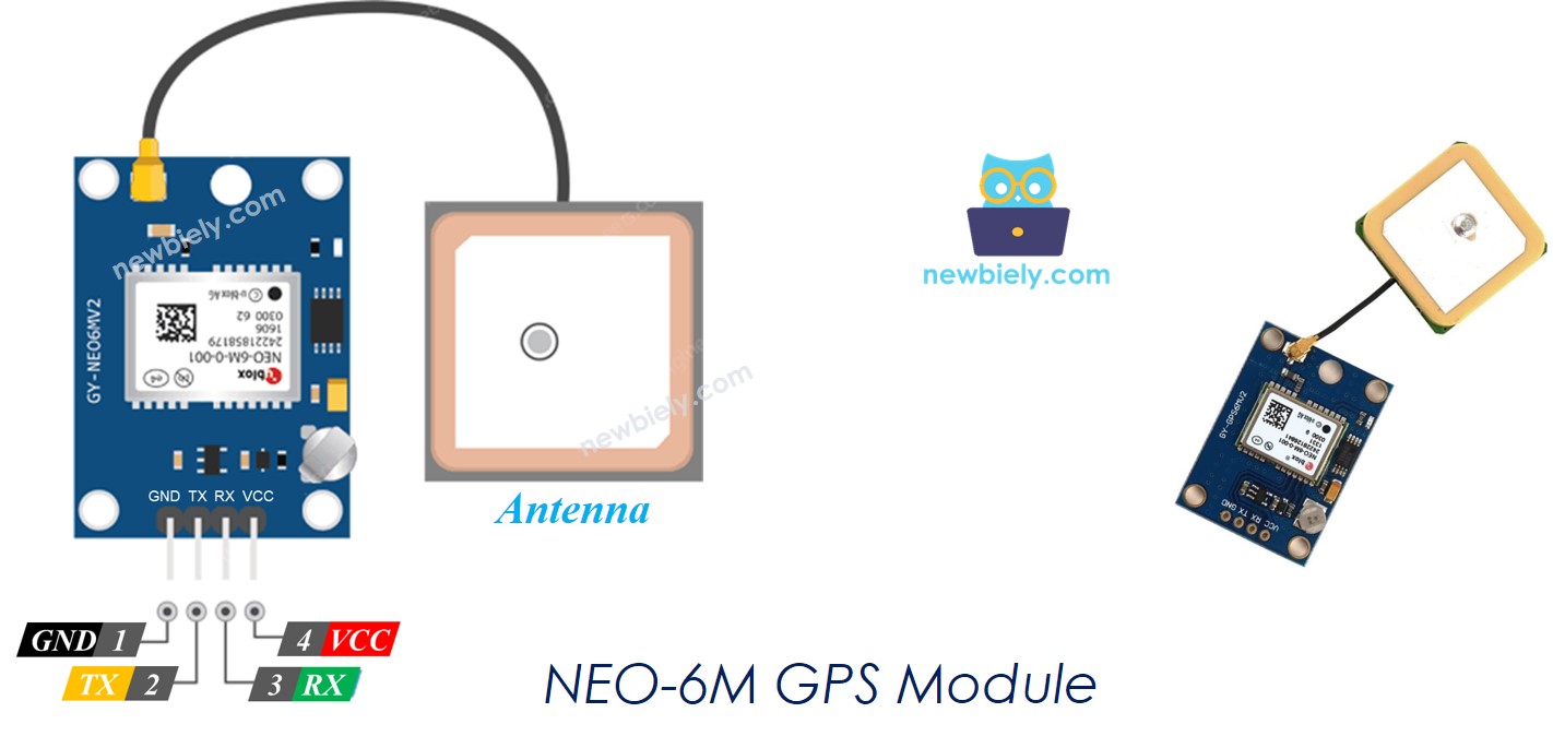
Pinout
Understanding the pin configuration is essential for proper connection. The NEO-6M GPS module features a straightforward four-pin interface that makes wiring simple and intuitive:
- VCC pin: This is the power supply pin. Connect it to 5V (VCC) to provide the necessary voltage for module operation
- GND pin: The ground reference pin. Connect this to ground (0V) to complete the power circuit
- TX pin: The transmit pin used to send GPS data from the module to your Arduino. Connect this to the RX pin of the Serial (or SoftwareSerial) interface on the Arduino Mega
- RX pin: The receive pin used to receive configuration commands. Connect this to the TX pin of the Serial (or SoftwareSerial) interface on the Arduino Mega
Note that while the TX/RX naming might seem counter-intuitive at first, remember that one device's transmit (TX) pin always connects to the other device's receive (RX) pin, creating a proper communication channel.
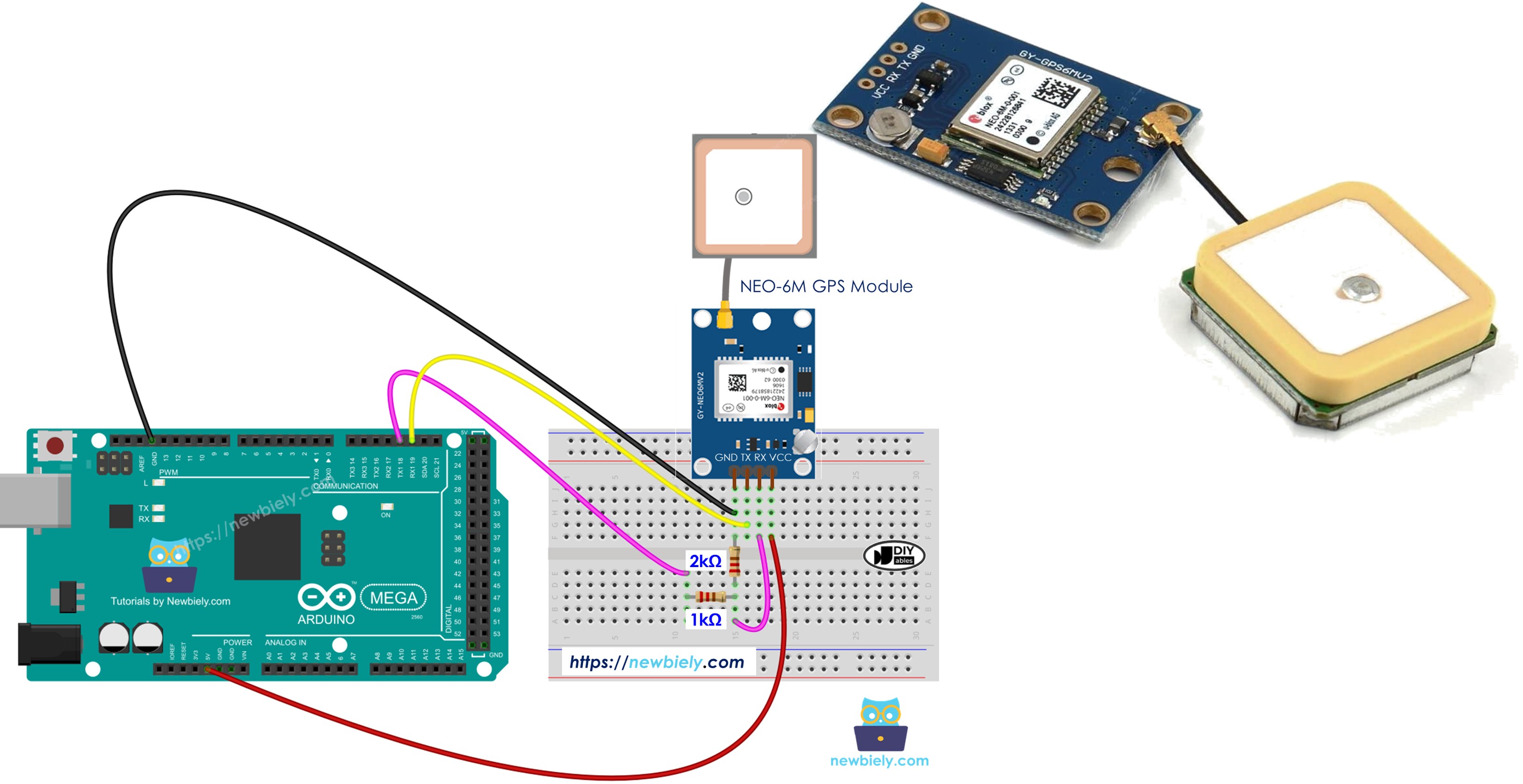
Wiring Diagram
Now let's examine the proper way to establish electrical connections between your Arduino Mega and the GPS module.
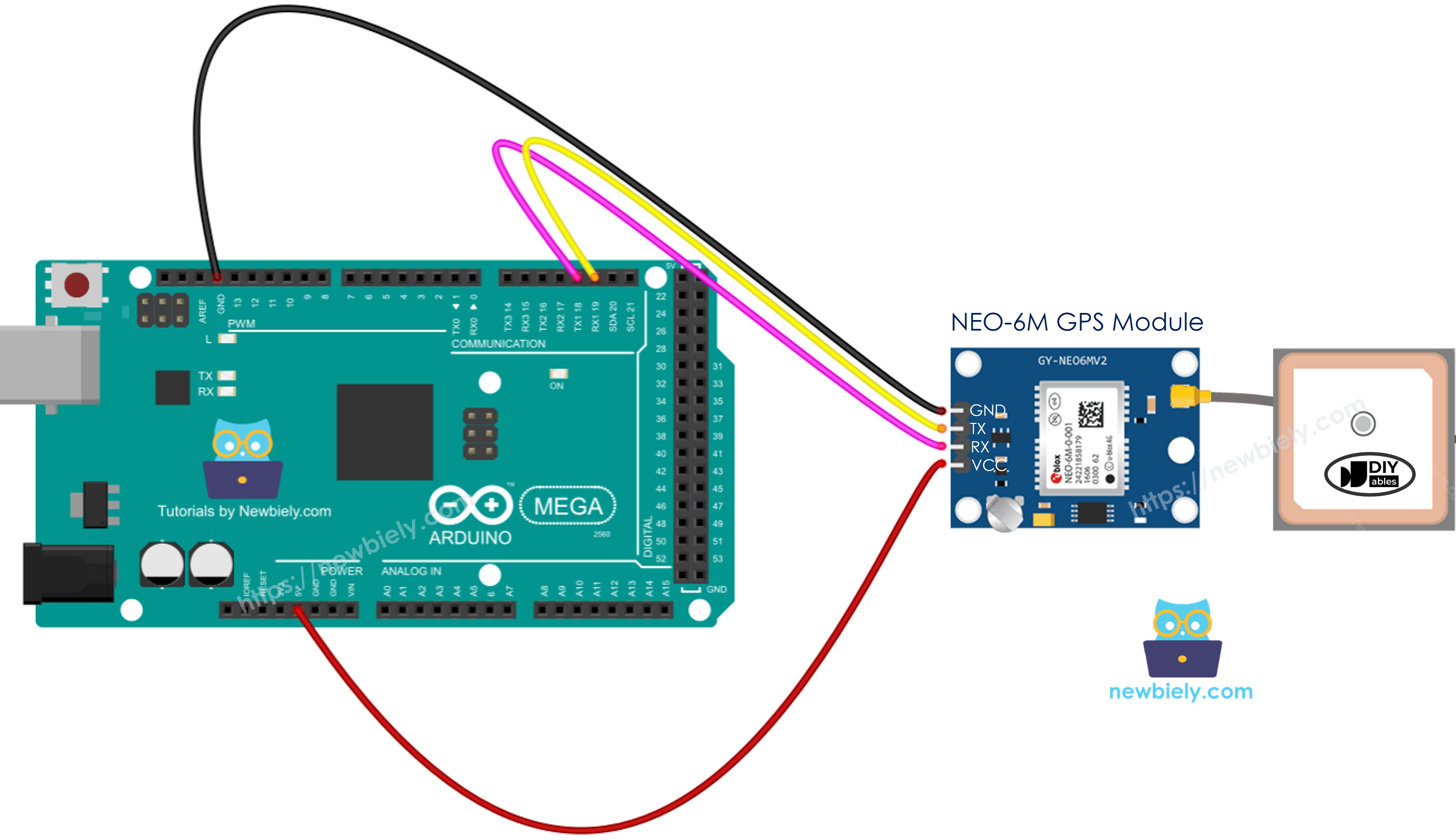
This image is created using Fritzing. Click to enlarge image
Important Safety Note: While the wiring diagram shown above may function, it's not the recommended approach for long-term reliability. Here's why: The Arduino Mega's TX pin outputs a 5V logic level signal, whereas the GPS module's RX pin is designed to safely handle only 3.3V. Connecting 5V directly to a 3.3V input can potentially damage the GPS module over time or cause unreliable operation.
To ensure safe and reliable communication, it's highly recommended to implement a voltage divider circuit between the Arduino TX pin and the GPS RX pin. This simple circuit reduces the 5V signal to a safe 3.3V level that won't harm your GPS module. The improved wiring diagram below demonstrates this protective configuration:
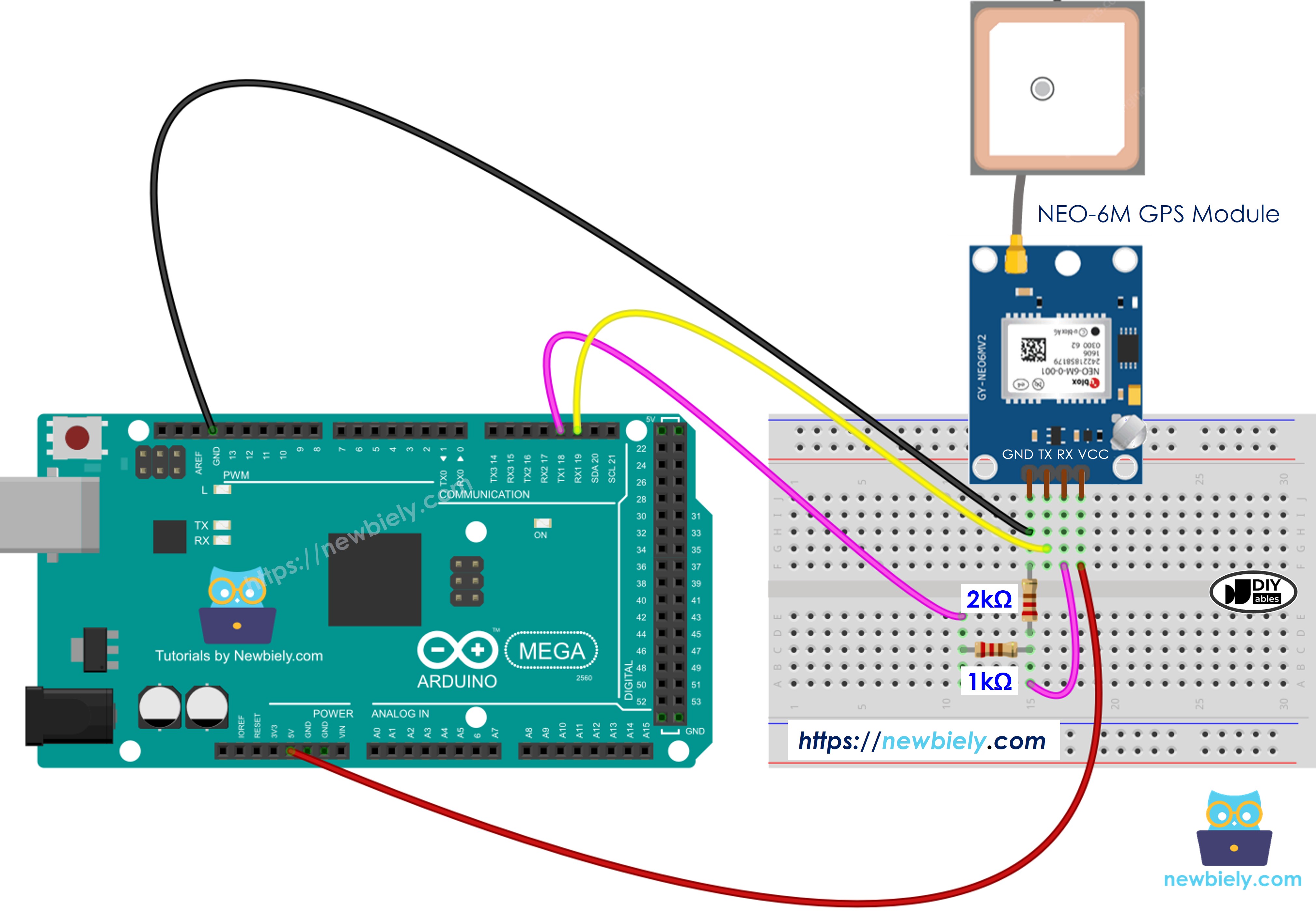
This image is created using Fritzing. Click to enlarge image
By using the voltage divider (typically created with two resistors), you protect your investment in the GPS module and ensure consistent, reliable performance. This is a best practice that professional electronics designers always follow when interfacing components with different voltage levels.
Arduino Mega Code
Let's dive into the programming side of this project! The code examples below will show you exactly how to communicate with the GPS module and extract meaningful data from it.
Reading GPS coordinates, speed (km/h), and date time
In this first example, we'll write code that reads and displays the fundamental GPS data points: your geographical coordinates, current speed, and timestamp information. This forms the foundation for any GPS-based project you might want to build.
Detailed Instructions
Follow these detailed steps carefully to get your GPS project up and running. Take your time with each step to ensure everything is configured correctly:
- Step 1 - Physical Connection: Connect the Arduino Mega to the GPS module using the wiring diagram shown in the previous section. Double-check all connections to ensure they're secure and correct.
- Step 2 - USB Connection: Connect the Arduino Mega board to your computer using a USB cable. Wait a moment for your computer to recognize the device.
- Step 3 - Launch IDE: Open the Arduino IDE on your computer. If you don't have it installed yet, download it from the official Arduino website.
- Step 4 - Board Configuration: Choose the correct board type: Arduino Mega, and select the appropriate COM port from the Tools menu. This ensures the IDE communicates with your specific board.
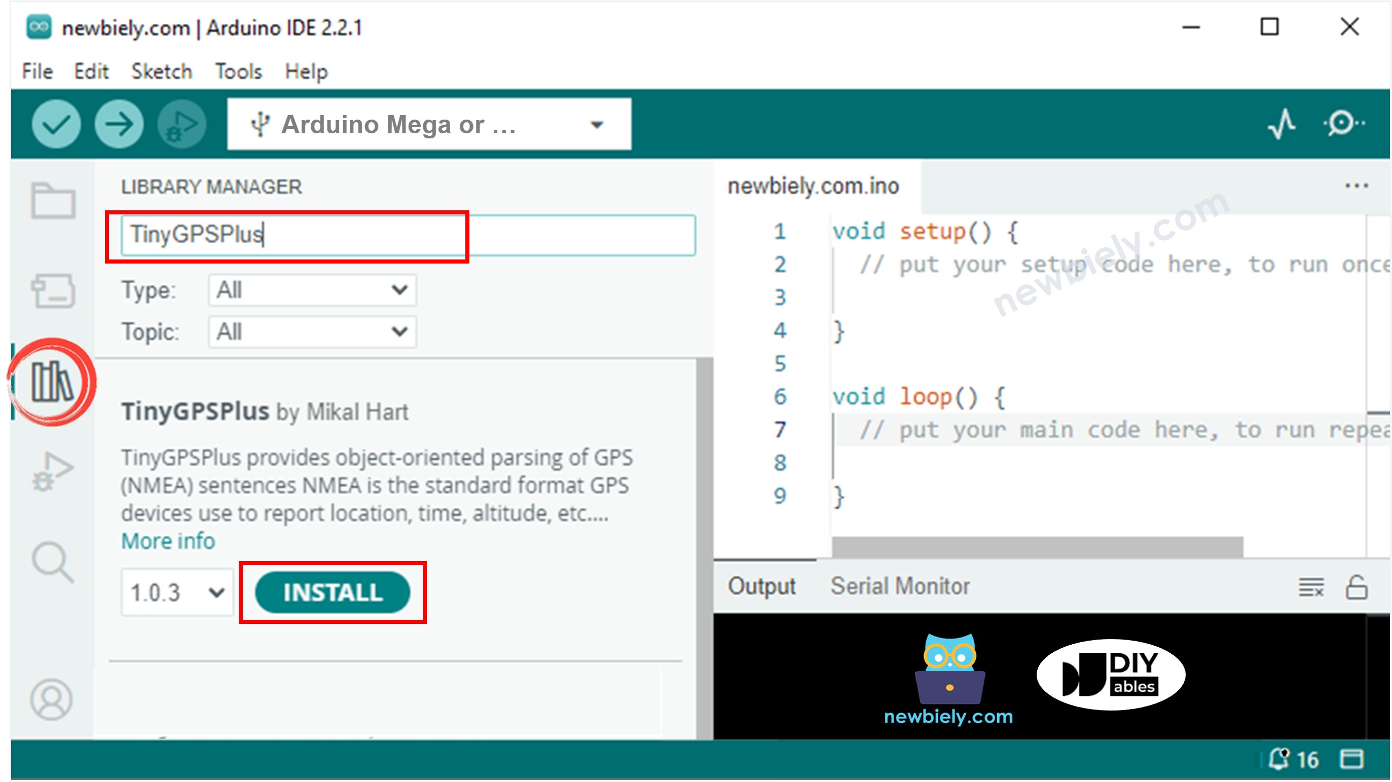
- Step 5 - Access Library Manager: Click on the Libraries icon on the left sidebar of the Arduino IDE. This opens the Library Manager where you can search for and install additional code libraries.
- Step 6 - Search for Library: In the search box at the top, type "TinyGPSPlus" and look for the TinyGPSPlus library created by Mikal Hart. This excellent library simplifies GPS data parsing significantly.
- Step 7 - Install Library: Click the Install button to add the TinyGPSPlus library to your Arduino IDE. This library handles all the complex NMEA sentence parsing for you.
- Step 8 - Load Code: Copy the code provided above and open it in the Arduino IDE. Take a moment to review the code and understand what each section does.
- Step 9 - Upload Program: Press the Upload button (the right-arrow icon) in the Arduino IDE to compile and send the code to the Arduino Mega. Wait for the "Done uploading" message.
- Step 10 - View Results: Open the Serial Monitor (Tools > Serial Monitor or Ctrl+Shift+M) to check the results. You should start seeing GPS data appear. Note that it may take a few minutes to acquire a GPS signal, especially if you're indoors.
Pro Tip: For best results, place your GPS module near a window or outdoors with a clear view of the sky. GPS signals are relatively weak and can be blocked by buildings, trees, or even thick clouds.
Calculating the distance from current location to a predefined location
Now let's explore something really exciting - calculating the distance between two points on Earth! This example demonstrates how to compute the distance between your current GPS position and any predefined location you choose.
In this specific implementation, we'll calculate how far you are from London, United Kingdom (latitude 51.508131, longitude -0.128002). The code uses the Haversine formula, which accounts for the spherical shape of Earth to provide accurate distance calculations. This technique is invaluable for navigation systems, geofencing applications, proximity alerts, and location-based services.
You can easily modify the target coordinates to calculate distances to any location you're interested in - perhaps your home, office, a favorite vacation spot, or a delivery destination!
Detailed Instructions
Ready to see the distance calculation in action? Follow these simple steps:
- Copy and Open: Copy the complete code provided above and open it in the Arduino IDE software. The code includes all necessary calculations built right in.
- Upload to Board: Press the Upload button (right-arrow icon) in the Arduino IDE to compile and transfer the code to your Arduino Mega. The process takes just a few seconds.
- Monitor Output: Open the Serial Monitor to see the results displayed in real-time. You'll see not only the distance to London but also your current coordinates and other GPS information.
Application Ideas: This distance calculation feature opens up numerous project possibilities. You could create a "treasure hunt" game, build a "return to home" function for an autonomous vehicle, set up geofencing alerts when you're within a certain distance of a location, or even track how far you've traveled on a road trip. The possibilities are limited only by your imagination!