Arduino Mega - LCD Keypad Shield
Welcome to this comprehensive Arduino Mega LCD Keypad Shield tutorial! In this detailed guide, you'll discover how to harness the power of one of the most popular and convenient Arduino accessories - the LCD Keypad Shield. This all-in-one expansion board combines a 16x2 character LCD display with five navigation buttons (Up, Down, Left, Right, Select) plus a Reset button, creating a complete user interface solution in a single, stackable module.
The LCD Keypad Shield revolutionizes Arduino project interfaces by eliminating the need for complex breadboard wiring. Instead of connecting 10+ jumper wires for an LCD and 5 more for buttons, you simply stack the shield on top of your Arduino Mega, and you're instantly ready to create interactive menus, sensor displays, settings screens, and user-controllable applications. This makes the LCD Keypad Shield perfect for rapid prototyping, educational projects, and finished products alike.
Throughout this Arduino Mega LCD Keypad Shield tutorial, we'll explore everything you need to master this versatile interface:
- Understanding the LCD Keypad Shield architecture and how it simplifies wiring
- Learning the pin mapping between the shield and Arduino Mega
- Button reading techniques using analog voltage levels on a single pin
- LCD programming with the LiquidCrystal library for text and data display
- Menu system creation for user navigation and settings
- Debouncing strategies for reliable button press detection
- Contrast adjustment for optimal display visibility
- Professional code structure with clean, maintainable functions
This Arduino Mega LCD Keypad Shield project opens up incredible interactive possibilities! Create user-configurable settings menus, multi-screen data dashboards, interactive games, sensor monitoring systems with user controls, thermostat interfaces, parameter adjustment tools, quiz machines, navigation menus for complex projects, and any application where users need to view information and make selections. The LCD Keypad Shield transforms your Arduino from a one-way output device into a complete interactive system!
Hardware Preparation
Or you can buy the following kits:
| 1 | × | DIYables Sensor Kit (18 sensors/displays) |
Additionally, some of these links are for products from our own brand, DIYables .
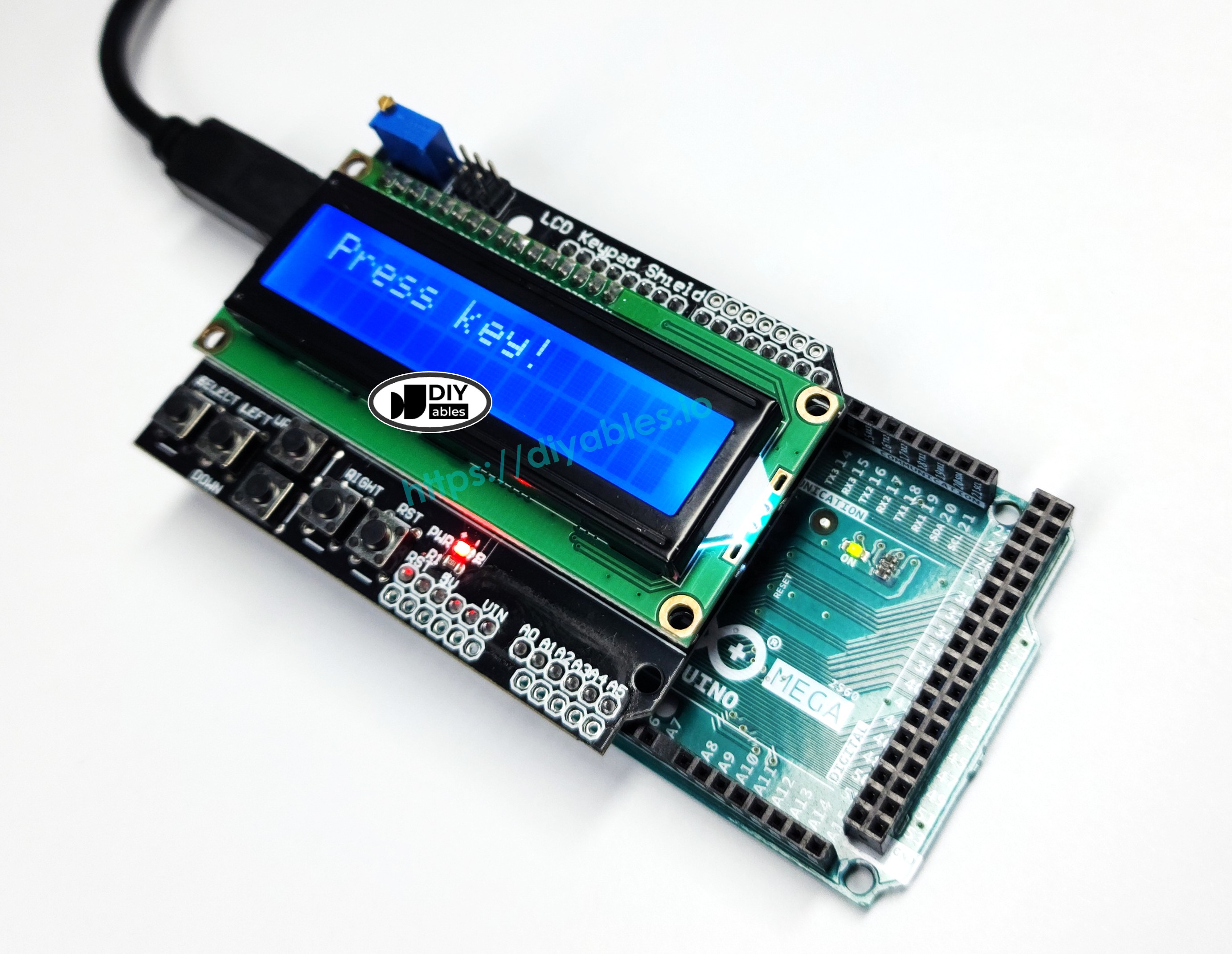
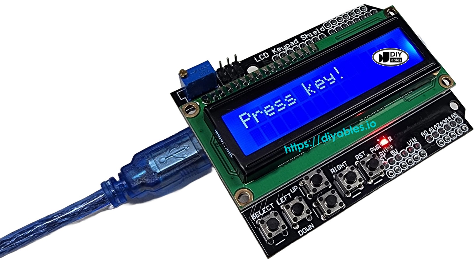
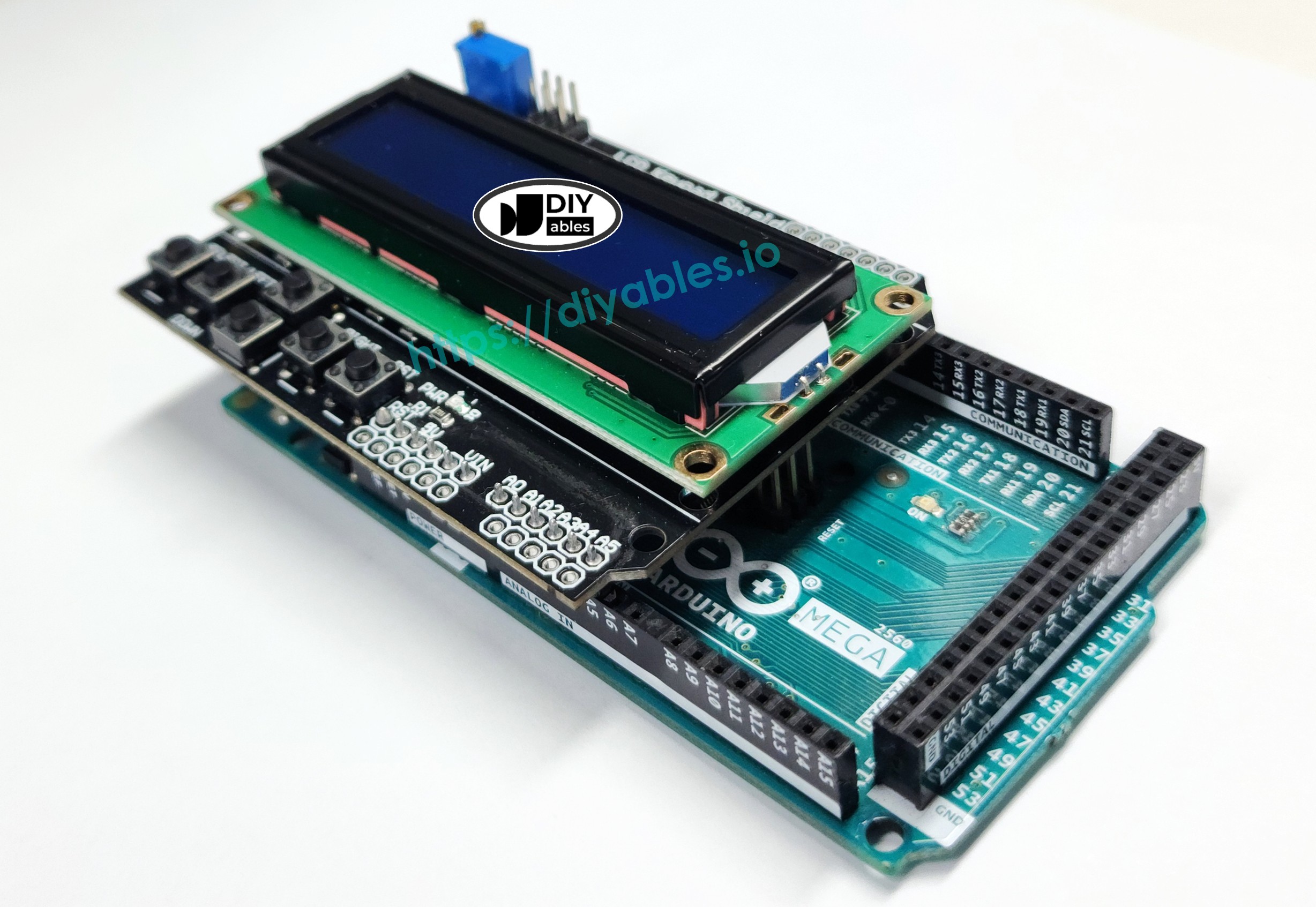
Overview of the LCD Keypad Shield
The LCD Keypad Shield is an all-in-one expansion board that combines a character-based liquid crystal display with integrated push buttons, creating a complete human-machine interface (HMI) for Arduino projects. This shield follows the standard Arduino form factor, allowing it to be stacked directly onto Arduino Mega boards without any external wiring.
Key Components:
1. 16x2 Character LCD Display
- Display Capacity: 32 characters total (16 columns × 2 rows)
- Character Size: Each character is formed by a 5×8 pixel matrix
- Library Compatibility: Works with the standard Arduino LiquidCrystal library
- Backlight: Blue LED backlight for visibility in low-light conditions
- Controller: HD44780-compatible LCD controller chip
- Display Interface: Uses 6 Arduino pins (DB4-DB7, RS, E) in 4-bit parallel mode
2. Five Navigation Buttons
- Button Types: Up, Down, Left, Right, and Select (tactile push buttons)
- Unique Design: All five buttons share a single analog input pin (A0) through a resistor ladder network
- Analog Reading: Each button produces a unique voltage level when pressed, allowing one pin to detect five different buttons
- Debouncing: May require software debouncing for reliable operation
- Function: Perfect for menu navigation, value adjustment, and user selections
3. Reset Button
- Function: Directly connected to the Arduino's RESET pin
- Purpose: Allows convenient program restart without disconnecting power
- Location: Typically positioned near the LCD for easy access
4. Contrast Adjustment Potentiometer
- Type: Small blue or white trimmer potentiometer (typically 10kΩ)
- Function: Adjusts LCD contrast for optimal text visibility
- Adjustment: Turn with small screwdriver clockwise or counterclockwise
- Important: Must be adjusted correctly or LCD will show blank or all-black squares
How the Button Resistor Network Works:
The LCD Keypad Shield uses a clever voltage divider circuit where each button is connected to a different resistor value. When a button is pressed, it creates a unique voltage at pin A0:
- Right button: ~0V (ADC reading < 50)
- Up button: ~0.71V (ADC reading < 200)
- Down button: ~1.61V (ADC reading < 400)
- Left button: ~2.47V (ADC reading < 600)
- Select button: ~3.62V (ADC reading < 800)
- No button: ~5V (ADC reading ≥ 1000)
Note: The threshold values above are practical ranges used in code for reliable button detection. Different shield manufacturers may use slightly different resistor values, so you may need to calibrate these thresholds by reading the raw analog values with analogRead(A0) and adjusting accordingly.
This voltage division technique saves Arduino pins - instead of needing 5 digital pins for 5 buttons, you only need 1 analog pin! The software reads the analog value and determines which button (if any) is pressed based on the voltage range.
Advantages of Using the LCD Keypad Shield:
- Zero Wiring: Simply stack on top of Arduino - no jumper wires needed
- Compact: All components integrated into a single PCB
- Cost-Effective: Cheaper than buying LCD and buttons separately
- Reliable: Factory-tested connections eliminate wiring errors
- Professional: Clean appearance for finished projects
- Rapid Prototyping: Start coding interface immediately
- Pin Efficient: Uses only 7 pins total (6 LCD + 1 button input)
Pinout
Understanding the LCD Keypad Shield pinout is essential for proper initialization in your code and troubleshooting. The shield uses a standard pin configuration that's automatically connected when you stack it on your Arduino Mega.
LCD Data and Control Pins:
The table below shows how the LCD Keypad Shield internally connects to Arduino Mega pins when the shield is properly mounted:
| Shield Pin | Function | Arduino Mega Pin |
|---|---|---|
| DB4 | Data Bit 4 | 4 |
| DB5 | Data Bit 5 | 5 |
| DB6 | Data Bit 6 | 6 |
| DB7 | Data Bit 7 | 7 |
| RS | Register Select | 8 |
| E | Enable | 9 |
| Analog A0 | Button Input | A0 |
Detailed Pin Functions:
- DB4-DB7 (Data Bits 4-7): These four pins carry data between the Arduino and the LCD controller in 4-bit mode. This mode uses only 4 data lines instead of 8, saving Arduino pins while still providing full LCD functionality. Each character command is sent in two 4-bit nibbles.
- RS (Register Select): This control pin tells the LCD whether the data being sent is a command (RS=LOW) or character data to display (RS=HIGH). For example, clearing the screen is a command, while displaying "A" is character data.
- E (Enable): This control pin acts as a clock signal. Data is latched into the LCD on the falling edge of the Enable pulse. Every data transfer requires toggling this pin.
- Analog A0 (Button Input): This single analog pin reads all five buttons through a resistor ladder network. The analogRead() function returns different values (0-1023) depending on which button is pressed, allowing one pin to detect five buttons.
Additional Shield Components:
- Reset Button: Physically connected to the Arduino Mega's RESET pin. Press this button to restart your program from the beginning without disconnecting power. Useful during development and debugging.
- Contrast Potentiometer (Trim Pot): A small blue or white adjustable resistor on the shield. Turn it clockwise or counterclockwise using a small screwdriver to adjust LCD contrast. If your display shows nothing or shows all black squares, adjust this potentiometer first!
Power Connections:
The shield automatically connects to the Arduino's 5V and GND pins through the stacking headers. No external power supply is needed - the shield draws approximately 20-50mA total (mostly for the LCD backlight).
Important Notes:
- These pin assignments are fixed in hardware on the shield - you cannot change them
- When initializing the LiquidCrystal library in code, you must specify these exact pin numbers
- Some Arduino shields may have slightly different pin assignments - always check your shield's documentation
- The Arduino Mega has plenty of free pins even with the shield attached (pins 10-53 and A1-A15 are available)
Wiring Diagram
One of the greatest advantages of the LCD Keypad Shield is the elimination of complex wiring! Unlike traditional breadboard setups that require dozens of jumper wires connecting the LCD and buttons, this shield uses a stackable design where all connections are made automatically through the pin headers.
Installation Steps:
- Ensure Arduino is Powered Off: Disconnect the USB cable and any external power supply before installing the shield.
- Align the Shield: Hold the LCD Keypad Shield above your Arduino Mega, aligning the two rows of female headers on the shield with the male pin headers on the Arduino board.
- Check Alignment: Verify that all pins are properly aligned before pressing down. The shield should sit parallel to the Arduino board.
- Press Firmly: Apply even pressure to seat the shield completely onto the Arduino. All pins should be fully inserted into the headers - no pins should be visible sticking out.
- Verify Connection: The shield should sit flush against the Arduino with no gap between them. Gently rock the shield - it should not move or feel loose.
This image is created using Fritzing. Click to enlarge image
Connection Details:
When properly seated, the shield's female headers automatically make electrical contact with the Arduino Mega's pins:
- LCD data pins (DB4-DB7) connect to digital pins 4-7
- LCD control pins (RS, E) connect to digital pins 8-9
- Button input connects to analog pin A0
- Power (5V and GND) connections are established
- Reset button connects to the RESET pin
Important Installation Notes:
- Pin Bending: Be very careful not to bend any pins during installation. Bent pins can cause intermittent connections or prevent proper seating.
- Shield Orientation: The LCD display should face up (away from the Arduino). The blue potentiometer should be accessible from the side.
- Stacking Additional Shields: You can stack other shields on top of the LCD Keypad Shield, but be aware of pin conflicts. Check that other shields don't use pins 4, 5, 6, 7, 8, 9, or A0.
- Removal: To remove the shield, grasp it firmly on both sides and pull straight up with even force. Never pull from one side only, as this can bend pins.
No External Wiring Required:
Unlike traditional LCD setups that require:
- 6 wires for LCD data and control (DB4, DB5, DB6, DB7, RS, E)
- 5 wires for buttons (one per button)
- 2 wires for power (5V, GND)
- Pull-up or pull-down resistors for buttons
- Contrast control circuit
The LCD Keypad Shield has all of this built in! The shield's PCB contains all necessary resistors, connections, and the contrast potentiometer, providing a clean, professional appearance with zero external wiring.
Arduino Mega Code
Detailed Instructions
Follow these detailed step-by-step instructions to get your LCD Keypad Shield working with your Arduino Mega:
1. Shield Installation: Ensure your Arduino Mega is unplugged. Carefully align the LCD Keypad Shield's female headers with the Arduino Mega's male pins. Press down firmly and evenly until the shield sits flush on top of the Arduino board. Verify all pins are fully seated.
2. USB Connection: Connect the Arduino Mega (with shield attached) to your computer using a USB cable. Wait for your operating system to recognize the board.
3. Open Arduino IDE: Launch the Arduino IDE software on your computer.
4. Board Selection: Navigate to Tools → Board and select "Arduino Mega or Mega 2560" from the list of available boards.
5. Port Selection: Go to Tools → Port and choose the COM port (Windows) or /dev/ttyUSB or /dev/ttyACM port (Mac/Linux) that corresponds to your Arduino Mega.
6. Copy Code: Copy the example code provided above (the complete sketch including all functions).
7. Paste into IDE: Create a new sketch in Arduino IDE (File → New) and paste the code, replacing any default template code.
8. Upload Code: Click the Upload button (right arrow icon) in the Arduino IDE toolbar to compile and upload the code to your Arduino Mega. Wait for the "Done uploading" message.
9. Initial Display: After upload completes, the LCD should immediately display "Key:NONE" on the first line, indicating no button is currently pressed.
10. Test Buttons: Press each button on the shield one at a time:
- Press Select - Display should show "Key:SELECT"
- Press Left - Display should show "Key:LEFT"
- Press Up - Display should show "Key:UP"
- Press Down - Display should show "Key:DOWN"
- Press Right - Display should show "Key:RIGHT"
- Release all buttons - Display should return to "Key:NONE"
11. Observe Response: The LCD should update instantly when you press each button, displaying the button name on the screen.
12. Contrast Adjustment (if needed): If the LCD display is blank or shows only black rectangles:
- Locate the small blue potentiometer on the shield (usually near the LCD)
- Use a small flathead screwdriver to turn it slowly clockwise
- Continue turning until text becomes visible
- Fine-tune for optimal contrast
- The display should show clear, readable text when properly adjusted
Troubleshooting
If your LCD Keypad Shield isn't working as expected, follow these systematic troubleshooting steps:
Problem 1: LCD Display is Completely Blank
Solutions:
- Adjust Contrast: The most common issue! The contrast potentiometer may be set incorrectly.
- Locate the small blue or white trim pot on the shield
- Turn it slowly with a small screwdriver (both directions)
- You should see the display go from blank → faint text → clear text → black boxes
- Stop when text is clearly visible
- Power off the Arduino completely
- Remove the shield and inspect for bent pins
- Realign and press firmly until fully seated
- All pins should be inserted - no gaps between boards
- Verify Power: Ensure the Arduino is receiving power.
- Check that the USB cable is securely connected
- Look for the power LED on the Arduino (should be lit)
- Try a different USB port or cable
- Check Code: Verify the LiquidCrystal initialization matches your shield.
- Ensure pin numbers in code are: LiquidCrystal lcd(8, 9, 4, 5, 6, 7)
- Verify lcd.begin(16, 2) is called in setup()
- Check that code uploaded successfully
- Wrong Pin Configuration: Pin numbers in code don't match shield.
- Use the standard configuration: pins 8, 9, 4, 5, 6, 7
- Double-check initialization: LiquidCrystal lcd(8, 9, 4, 5, 6, 7)
- Poor Connection: Intermittent contact between shield and Arduino.
- Remove and reseat the shield firmly
- Clean pin headers with isopropyl alcohol if oxidized
- Contrast Too High: May appear as all black blocks.
- Adjust contrast potentiometer counterclockwise
- Check Button Threshold Values: Different shields have slightly different resistor values.
- Upload a simple analog read sketch to see actual values:
- Press each button and note the value
- Adjust threshold ranges in your button detection code
- Add Debouncing: Buttons may register multiple presses.
- Add delay(200) after button detection
- Or use more sophisticated debouncing algorithms
- Verify A0 Connection: Ensure analog pin A0 is properly connected.
- Check that shield is fully seated
- Verify no other code is using pin A0
- Use lcd.setCursor(0, 1) to move to second line (row index is 0 or 1)
- Verify lcd.begin(16, 2) specifies 2 rows
- If not working, shield may not be fully seated
- Check that RESET pin isn't bent
- Verify the physical button isn't damaged
- Start Simple: Upload the basic example code first before trying complex programs
- Serial Monitor: Use Serial.println() to debug button values and program flow
- Voltage Check: Measure 5V between shield VCC and GND pins with multimeter
- Pin Conflicts: Ensure no other shields or code uses pins 4-9 or A0
- Library Version: Use the standard Arduino LiquidCrystal library (included with IDE)
Problem 2: LCD Shows Random Characters or Blocks
Solutions:
Problem 3: Buttons Don't Respond or Give Wrong Readings
Solutions:
Problem 4: Only Bottom Row of LCD Works
Solution: This usually indicates the second line isn't being addressed correctly.
Problem 5: Reset Button Doesn't Work
Solution: Reset button should always work as it's hardware-connected.
General Troubleshooting Tips:
If problems persist after trying these solutions, the shield itself may be defective. Test with a different Arduino board if available, or contact the shield manufacturer for support.
Advanced Code Example: Professional Structure
Now that you understand the basics, let's explore a more professional, maintainable code structure. This advanced example demonstrates software engineering best practices for LCD Keypad Shield projects.
What Makes This Code Better:
- Function Abstraction: Button reading is separated into a dedicated function, making the code more modular and reusable.
- Clear Return Values: The button reading function returns an integer code representing each button, making the main loop cleaner and more readable.
- Better Organization: The code follows a logical structure: declarations → setup → main loop → helper functions.
- Easier Maintenance: If you need to adjust button thresholds or add new buttons, you only modify one function instead of searching through the entire code.
- Scalability: This structure makes it easy to add menu systems, state machines, or more complex user interfaces later.
Code Structure Explained:
- Button Constants: Define meaningful names (btnRIGHT, btnUP, etc.) instead of magic numbers
- readButton() Function: Encapsulates all button reading logic and threshold values
- Main Loop: Simple and readable - just read button and display result
- Threshold Ranges: Uses voltage ranges to determine which button is pressed based on analog reading
Professional Practices Demonstrated:
- Descriptive constant names improve code readability
- Single Responsibility Principle: each function does one thing well
- DRY (Don't Repeat Yourself): button logic isn't duplicated
- Clear function naming: readButton() tells you exactly what it does
- Comments explain the "why" not just the "what"
When to Use This Structure:
- Building menu systems with multiple screens
- Creating configuration interfaces
- Developing products for other users
- Working in teams where code clarity matters
- Projects that will be maintained or expanded over time
Practical Tips for LCD Keypad Shield Projects
Button Reading Best Practices:
- Calibrate Your Shield: Each shield may have slightly different resistor values. Upload a test sketch that prints the raw analog values for each button, then adjust your threshold ranges accordingly.
- Add Debouncing: Physical buttons can "bounce" - registering multiple presses from a single press. Add a small delay (100-200ms) after detecting a button press, or implement more sophisticated debouncing.
- Non-Blocking Code: Avoid using delay() in button reading. Instead, use millis() for timing to keep your program responsive.
- State Tracking: Keep track of button state (pressed/released) to detect button press and release events separately.
LCD Display Optimization:
- Minimize lcd.clear(): Clearing the entire display causes flicker. Instead, overwrite specific sections by printing spaces or using setCursor() to update only what changed.
- Update Only When Needed: Don't redraw the display every loop iteration. Only update when data actually changes.
- Contrast Matters: Proper contrast adjustment dramatically improves readability. Take time to adjust it perfectly.
- Custom Characters: Create custom characters (battery icons, arrows, special symbols) using lcd.createChar() for a more professional appearance.
Power Considerations:
- The LCD backlight draws 20-40mA. For battery-powered projects, consider adding a timeout to turn off the backlight after inactivity.
- The entire shield typically draws 50-80mA total.
- Use lcd.noDisplay() to turn off the display (but not backlight) to save power.
- For projects with external power, the USB connection provides sufficient current.
Code Organization Tips:
- Use Enums: Define button constants with enum for cleaner code:
- Separate Display Logic: Create functions like updateDisplay(), showMenu(), showSensorData() to organize your code.
- State Machines: For complex interfaces with multiple screens, implement a state machine pattern.
- Comment Your Thresholds: Document why you chose specific analog threshold values for button detection.
Common Pitfalls to Avoid:
- Pin Conflicts: Don't try to use pins 4-9 or A0 for other purposes while the shield is attached.
- Forgotten lcd.begin(): Always call lcd.begin(16, 2) in setup() before using the LCD.
- Wrong Cursor Position: Remember that setCursor(column, row) uses zero-based indexing.
- Blocking Code: Long delay() calls make buttons feel unresponsive.
- No Error Handling: Check button ranges and add default cases to prevent unexpected behavior.
Menu System Design Patterns:
When building menu systems:
- Use Up/Down to navigate between options
- Use Select to choose an option
- Use Left as "Back" to return to previous menu
- Use Right to enter sub-menus or increase values
- Always show the current selection clearly
- Provide visual feedback (arrows, highlights) for navigation
Performance Tips:
- Button reading via analogRead() is fast (takes ~100 microseconds)
- LCD updates are relatively slow (several milliseconds per character)
- Structure your loop() to read buttons frequently but update LCD sparingly
- Consider using timer interrupts for critical timing while updating display
Next Steps and Additional Resources
Expanding Your LCD Keypad Shield Projects:
Now that you've mastered the basics of the LCD Keypad Shield, here are exciting ways to expand your projects:
1. Create Multi-Screen Menus
- Build navigation menus where users select options
- Implement sub-menus and hierarchical structures
- Add "back" functionality using the Left button
- Store user selections in variables or EEPROM
2. Add Sensor Data Display
- Connect temperature, humidity, or distance sensors
- Display real-time sensor readings on the LCD
- Use buttons to switch between different sensor views
- Implement min/max value tracking
3. Build Interactive Settings Interfaces
- Create adjustable parameters (time, temperature, thresholds)
- Use Up/Down buttons to increment/decrement values
- Use Select button to confirm settings
- Save settings to EEPROM for persistence
4. Develop Simple Games
- Create reaction time games
- Build number guessing games
- Implement quiz applications
- Make simple adventure text games
5. Build Configuration Systems
- WiFi SSID/password entry systems
- Alarm clock time setting
- Timer/countdown configuration
- Device calibration interfaces
Advanced Techniques to Explore:
- Custom Characters: Create special symbols and icons using lcd.createChar()
- Scrolling Text: Implement marquee-style scrolling for long messages
- Progress Bars: Display loading or completion status visually
- Animation: Create simple animations using custom characters
- State Machines: Implement complex multi-state interfaces
- Debouncing: Add sophisticated button debouncing for better reliability
Project Ideas to Try:
- Temperature Controller: Display temperature and adjust setpoint with buttons
- Digital Clock: Show time with buttons to set hours/minutes
- Countdown Timer: Set duration with buttons, display remaining time
- Password Lock: Create PIN entry system with Select to confirm
- Data Logger: Display sensor data with buttons to browse history
- Calculator: Simple calculator using buttons for number entry
- Quiz Game: Display questions, use buttons to select answers
- Settings Menu: Multi-level menu system for device configuration
- Alarm System: Show status, arm/disarm with buttons
- RGB LED Controller: Adjust colors using Up/Down buttons
That's it! You're now fully equipped to create sophisticated interactive interfaces with your LCD Keypad Shield. The combination of display feedback and button input opens up endless possibilities for user-friendly Arduino projects. Have fun building!