Arduino Mega - Ethernet Module
Welcome to this comprehensive Arduino Mega Ethernet module tutorial! In this detailed guide, you'll discover how to connect your Arduino Mega to the internet and local networks using the powerful W5500 Ethernet module, transforming your microcontroller into a fully networked device capable of communicating with web servers, IoT platforms, and other network-connected devices worldwide.
The W5500 Ethernet module represents one of the most reliable and straightforward ways to add wired network connectivity to Arduino projects. Unlike WiFi modules that can suffer from signal interference and connection instability, Ethernet provides rock-solid, high-speed network connections with deterministic performance—perfect for industrial automation, home automation systems, data logging servers, remote monitoring applications, and any project requiring dependable internet connectivity. The W5500 chip handles all the heavy lifting of TCP/IP protocol stack implementation, leaving your Arduino free to focus on application logic.
Throughout this Arduino Mega W5500 Ethernet tutorial, we'll explore everything you need to master wired network connectivity:
- Understanding the W5500 Ethernet module: Hardware features, SPI communication interface, and network capabilities
- Wiring and connection: Properly connecting the Ethernet module to Arduino Mega via SPI pins
- Network configuration: Setting IP addresses, subnet masks, gateways, and MAC addresses
- HTTP client programming: Making HTTP GET and POST requests to web servers and APIs
- Web server implementation: Creating Arduino-based web servers that respond to browser requests
- TCP/IP socket programming: Establishing direct socket connections for custom protocols
- DHCP configuration: Automatic IP address assignment from network routers
- DNS resolution: Converting domain names to IP addresses
- Network troubleshooting: Common issues and diagnostic techniques
- Security considerations: Best practices for network-connected Arduino devices
This Arduino Mega Ethernet project opens up incredible networking possibilities! Create IoT sensor networks that upload data to cloud platforms, build home automation web interfaces accessible from any browser, develop remote control systems for industrial equipment, implement data loggers that email reports, create REST API clients for third-party services, build networked game systems, develop real-time monitoring dashboards, implement MQTT clients for smart home integration, and any application requiring reliable, high-speed network connectivity.
Hardware Preparation
Or you can buy the following kits:
| 1 | × | DIYables Sensor Kit (18 sensors/displays) |
Additionally, some of these links are for products from our own brand, DIYables .
Overview of W5500 Ethernet Module
The W5500 Ethernet module is a hardwired network interface controller that provides reliable, high-speed TCP/IP connectivity for microcontroller projects. Built around the WIZnet W5500 chip, this module implements a full hardware TCP/IP protocol stack, handling all network communication complexity internally and communicating with the Arduino Mega through a simple SPI (Serial Peripheral Interface) connection.
Key Features and Specifications:
- Hardware TCP/IP Stack: The W5500 chip contains a complete TCP/IP protocol stack implemented in hardware, eliminating the need for software protocol libraries that consume precious Arduino memory and processing power
- Network Speed: Supports 10/100 Mbps Ethernet (auto-negotiation)
- Simultaneous Connections: Handles up to 8 independent socket connections simultaneously
- Internal Memory: 32KB buffer memory for packet handling and queuing
- Power Consumption: Low power design, typically 132mA @ 100Mbps, 78mA @ 10Mbps
- Operating Voltage: 3.3V logic with 5V tolerant inputs, making it Arduino Mega compatible
- SPI Interface: High-speed SPI communication (up to 80MHz clock speed)
- Physical Layer: Integrated Ethernet PHY (Physical Layer) with RJ45 connector
- Protocol Support: TCP, UDP, IPv4, ICMP, ARP, IGMP, PPPoE
Physical Interfaces:
The W5500 Ethernet module provides two distinct interface types:
1. RJ45 Ethernet Interface (Network Connection):
- Standard RJ45 connector for Cat5/Cat5e/Cat6 Ethernet cables
- Connects to network routers, switches, or directly to computers
- LED indicators: Link status (connected/disconnected) and activity (data transmission)
- Auto-MDI/MDIX support: Works with both straight-through and crossover cables
- Cable length: Up to 100 meters (328 feet) for standard Cat5e cable
2. SPI Interface (Arduino Connection):
- 10-pin header for connection to microcontroller
- Uses standard SPI protocol: MOSI, MISO, SCK, CS signals
- Pin-compatible with most Arduino SPI-based shields
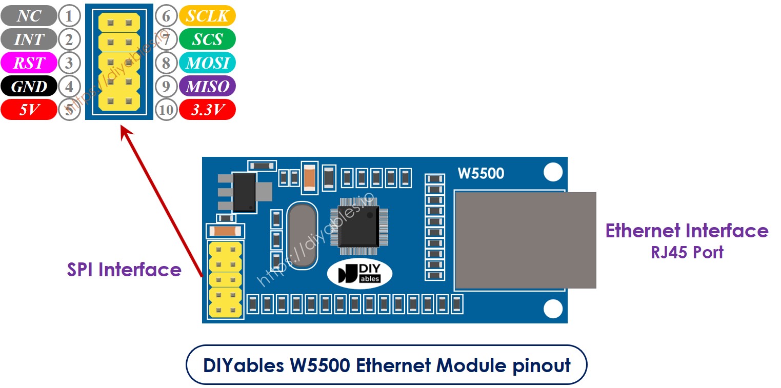
Detailed Pin Description:
Understanding each pin's function is essential for proper wiring and operation:
- NC pin: No Connection. This pin is not internally connected and should be left unconnected in your wiring. It serves as a mechanical placeholder in the pin header.
- INT pin: Interrupt output pin. This active-low interrupt signal can alert the Arduino when network events occur (packet received, connection established, etc.). For basic applications, this pin can be left unconnected. Advanced applications can connect it to an Arduino interrupt pin for event-driven network handling.
- RST pin: Hardware reset input (active low). This pin resets the W5500 chip when pulled LOW. Connect this to a digital pin on the Arduino Mega for software-controlled resets, or connect to the Arduino's RESET pin to reset the Ethernet module whenever the Arduino resets. Can also be left unconnected for simple applications, as the module has internal power-on reset.
- GND pin: Ground reference. Connect this to the Arduino Mega's GND pin to establish a common ground between the two devices. This is essential for proper SPI communication.
- 5V pin: Power supply input. Connect this to the Arduino Mega's 5V output pin to provide operating power to the module. The onboard voltage regulator converts 5V to the 3.3V required by the W5500 chip. Current draw is approximately 140-200mA during active use.
- 3.3V pin: 3.3V power output. This pin provides regulated 3.3V output from the module's onboard regulator. Can be used to power other 3.3V devices, but check the regulator's current capacity (typically 150-300mA). For Arduino Mega connection, leave this pin unconnected.
- MISO pin: Master In, Slave Out (SPI data line). This pin carries data from the W5500 module (slave) to the Arduino Mega (master). Connect to the Arduino Mega's SPI MISO pin (Digital Pin 50).
- MOSI pin: Master Out, Slave In (SPI data line). This pin carries data from the Arduino Mega (master) to the W5500 module (slave). Connect to the Arduino Mega's SPI MOSI pin (Digital Pin 51).
- SCS pin: Slave Chip Select (SPI select line). This active-low signal enables the W5500 chip for SPI communication. Connect to the Arduino Mega's SPI SS/CS pin (Digital Pin 53) or any other available digital pin (must be defined in code).
- SCLK pin: Serial Clock (SPI clock line). This pin carries the clock signal that synchronizes SPI data transmission. Connect to the Arduino Mega's SPI SCK pin (Digital Pin 52).
Advantages of W5500 Over Other Network Solutions:
- Hardware TCP/IP Stack: Unlike software-based solutions, the W5500's hardware stack doesn't consume Arduino RAM or processing cycles
- Reliable Connection: Wired Ethernet is immune to WiFi interference, signal strength issues, and wireless security concerns
- Lower Latency: Wired connections typically have 1-5ms latency vs. 50-100ms for WiFi
- Better for Industrial: Ethernet is standard in industrial environments where reliability is critical
- No Password Management: Unlike WiFi, Ethernet doesn't require SSID and password configuration
- Power Efficient: Once configured, Ethernet modules consume less power than constantly transmitting WiFi
- Multiple Protocols: Supports TCP, UDP, and other protocols simultaneously
When to Use Ethernet vs. WiFi:
Choose Ethernet (W5500) when:
- Project is stationary with access to wired network infrastructure
- Reliability and deterministic performance are critical
- Industrial or commercial environment
- High data throughput is required
- Security through physical access control is desired
- Power budget is limited (after initial setup)
Choose WiFi when:
- Project is mobile or frequently moved
- No Ethernet infrastructure available
- Wireless convenience outweighs reliability needs
- Project is consumer-facing where WiFi is expected
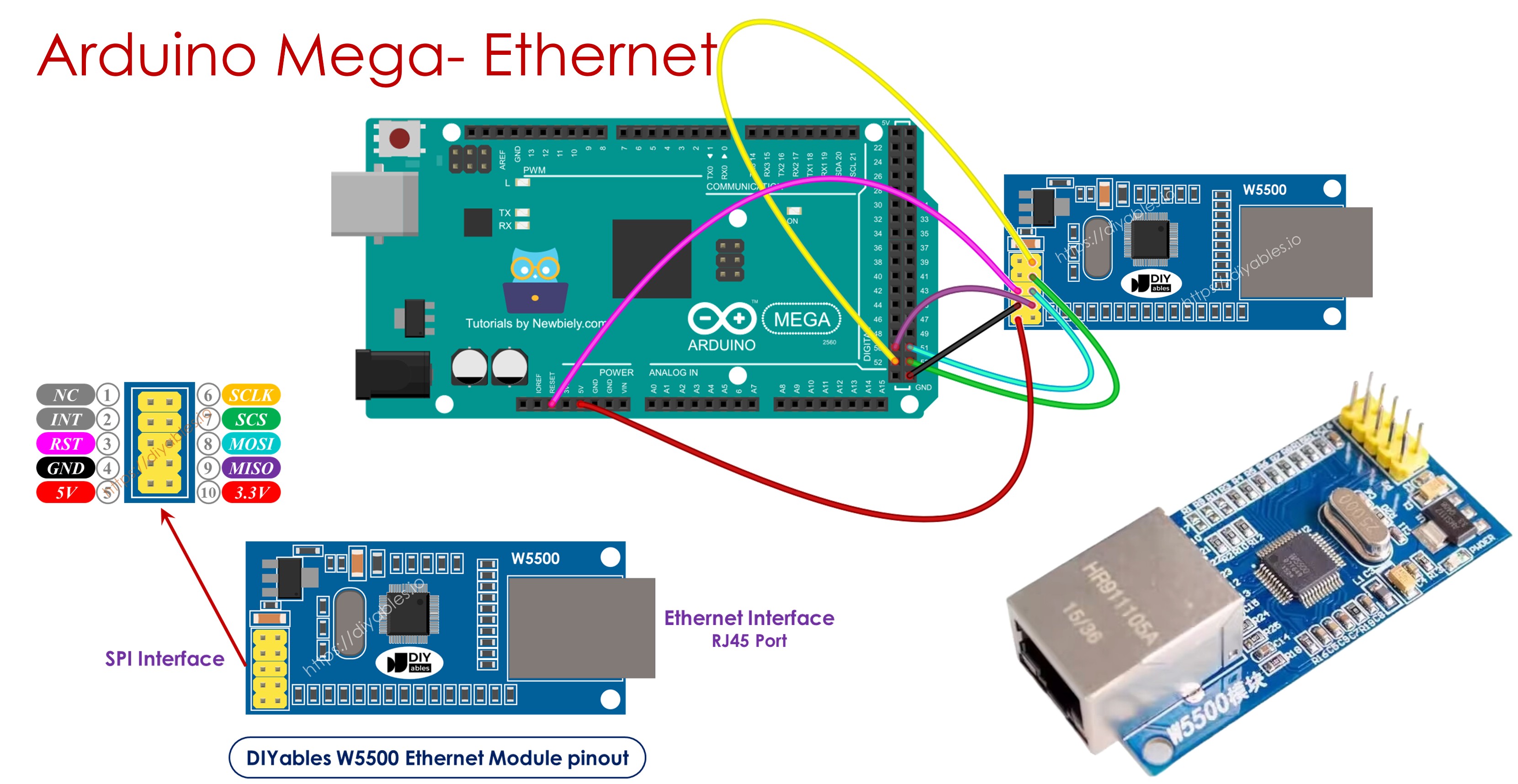
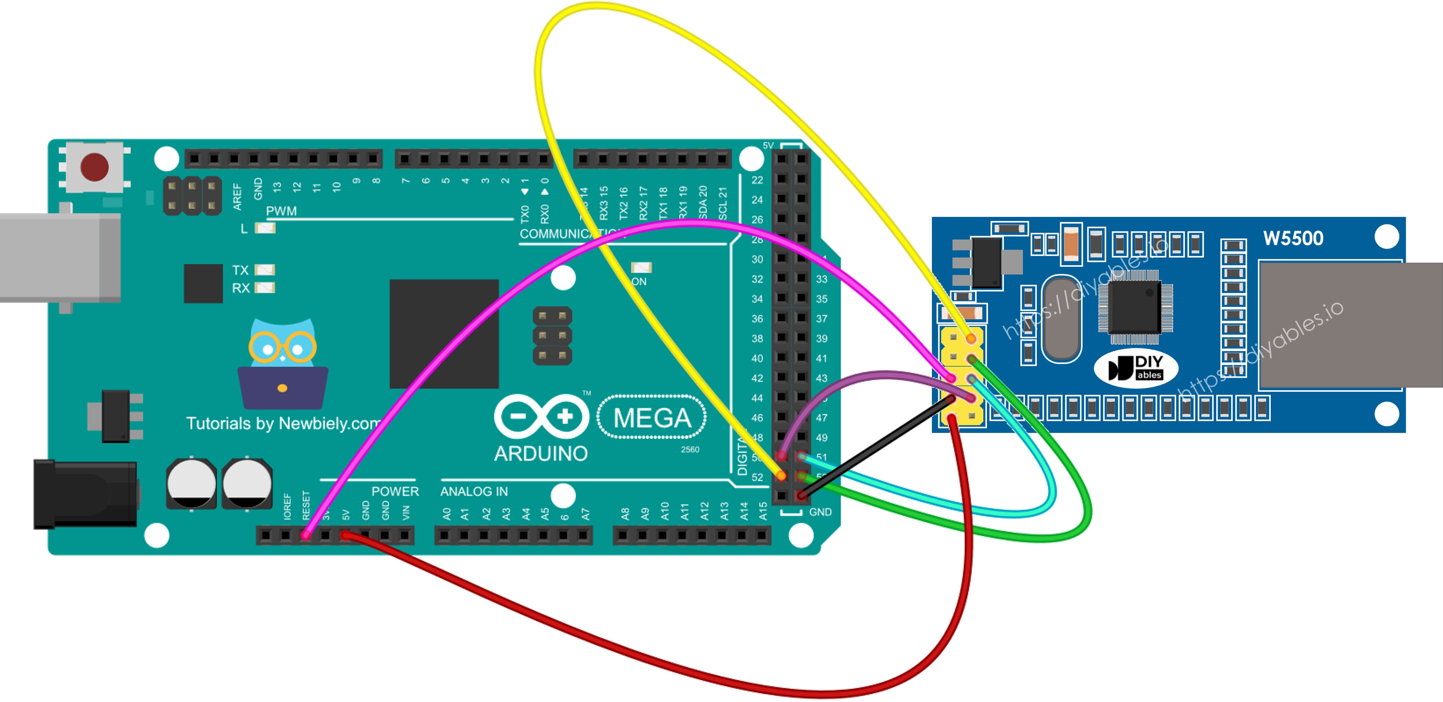
Wiring Diagram between Arduino Mega and W5500 Ethernet Module
Connecting the W5500 Ethernet module to your Arduino Mega requires careful attention to the SPI interface pins. The Arduino Mega has dedicated hardware SPI pins that provide optimized, high-speed communication with SPI devices like the W5500.
This image is created using Fritzing. Click to enlarge image
Detailed Connection Table:
The table below shows the complete wiring between the W5500 Ethernet module and Arduino Mega:
| W5500 Pin | Function | Arduino Mega Pin | Pin Name/Number |
|---|---|---|---|
| GND | Ground | GND | Ground |
| 5V | Power Supply | 5V | 5V Power |
| MISO | SPI Data Out | MISO | Digital Pin 50 |
| MOSI | SPI Data In | MOSI | Digital Pin 51 |
| SCLK | SPI Clock | SCK | Digital Pin 52 |
| SCS | Chip Select | SS | Digital Pin 53 |
| NC | No Connection | - | (Leave unconnected) |
| INT | Interrupt | - | (Optional, leave unconnected for basic use) |
| RST | Reset | - | (Optional, can connect to any digital pin) |
| 3.3V | 3.3V Output | - | (Leave unconnected) |
Critical Wiring Notes:
1. SPI Pin Locations on Arduino Mega:
The Arduino Mega's hardware SPI pins are different from smaller Arduino boards:
- MOSI: Pin 51 (NOT pin 11 as on Uno)
- MISO: Pin 50 (NOT pin 12 as on Uno)
- SCK: Pin 52 (NOT pin 13 as on Uno)
- SS/CS: Pin 53 (NOT pin 10 as on Uno)
Using the wrong pins is the most common wiring mistake. Always verify you're using the Mega's dedicated SPI pins!
2. Chip Select (SCS/SS) Pin:
While the default Chip Select is pin 53, you can use ANY digital pin for CS if you configure it correctly in your code. However, even if using an alternate CS pin, pin 53 must be configured as OUTPUT in your setup() function, or SPI master mode won't work properly:
3. Power Considerations:
The W5500 module draws 140-200mA during operation. When powered via USB, the Arduino Mega can supply up to 500mA total. If your project includes power-hungry components (motors, many LEDs, etc.), consider:
- Using an external 5V power supply for the Arduino
- Connecting the module's 5V pin to an external regulated 5V source (ensure common ground)
4. Ethernet Cable Connection:
After wiring the SPI interface:
- Connect an Ethernet cable (Cat5/Cat5e/Cat6) to the W5500's RJ45 jack
- Connect the other end to your network router, switch, or directly to a computer
- The link LED should illuminate when properly connected to an active network port
- The activity LED should blink during data transmission
5. Network Infrastructure Requirements:
- Router/Switch: Most home and office networks have a router or switch with spare Ethernet ports
- DHCP Server: For automatic IP assignment, your router must have DHCP enabled (typical default)
- Static IP: Alternatively, configure a static IP in the Arduino code (must be within network's subnet)
- Internet Access: For web client applications, your network needs internet connectivity
Connection Verification:
After wiring, verify your setup:
- Power LED: W5500 module should have a power indicator LED lit
- Link LED: Should illuminate when Ethernet cable is connected to active network
- Arduino Power: Arduino Mega power LED should be lit
- No Shorts: Verify no SPI wires are crossed or shorted
- Secure Connections: All jumper wires should be firmly seated
Common Wiring Mistakes:
- Using Uno SPI pins (11, 12, 13) instead of Mega pins (50, 51, 52)
- Forgetting to set pin 53 as OUTPUT even when using alternate CS pin
- Reversing MOSI and MISO connections
- Poor quality jumper wires causing intermittent connections
- Insufficient power supply for both Arduino and Ethernet module
- Not connecting ground between Arduino and Ethernet module
Arduino Mega Code for Ethernet Module - Making HTTP Request via Ethernet
This example program demonstrates how to use your Arduino Mega as an HTTP client—a device that requests and receives data from web servers across the internet. The code establishes a TCP connection to example.com (a demonstration web server), sends an HTTP GET request, receives the HTML response, and displays it in the Serial Monitor.
What This Code Does:
- Network Configuration: Sets up Ethernet with MAC address and automatic DHCP IP assignment
- DNS Resolution: Converts the domain name "example.com" to its IP address
- TCP Connection: Establishes a socket connection to the web server on port 80 (HTTP)
- HTTP Request: Sends a properly formatted HTTP GET request with required headers
- Response Handling: Receives and displays the complete HTTP response including headers and HTML content
- Connection Management: Properly closes the connection after receiving all data
Understanding HTTP Client Operation:
When you browse the web, your computer acts as an HTTP client. This Arduino code performs the same function:
- Connect to web server via TCP socket
- Send HTTP request specifying what you want (GET /path)
- Receive HTTP response containing requested data
- Close connection
This pattern enables Arduino to interact with web APIs, download data, submit sensor readings to cloud platforms, check for firmware updates, and communicate with any HTTP-based service.
This program works as a web client. It sends HTTP requests to the web server at http://example.com/.
Detailed Instructions
Follow these comprehensive step-by-step instructions to get your Arduino Mega making HTTP requests over Ethernet:
1. Physical Wiring: Connect the W5500 Ethernet module to your Arduino Mega following the wiring diagram provided above. Double-check all SPI connections: MISO to pin 50, MOSI to pin 51, SCK to pin 52, SCS to pin 53, plus 5V and GND connections.
2. Network Connection: Use a standard Ethernet cable (Cat5/Cat5e/Cat6) to connect the W5500 module's RJ45 jack to an available port on your network router or switch. Verify the link LED on the module illuminates, indicating successful physical connection.
3. USB Connection: Connect your Arduino Mega board to your computer using a USB cable. Wait for the operating system to recognize the device and install any necessary drivers.
4. Open Arduino IDE: Launch the Arduino IDE software on your computer.
5. Board Selection: Navigate to Tools → Board and select "Arduino Mega or Mega 2560" from the available boards list.
6. Port Selection: Go to Tools → Port and choose the COM port (Windows) or /dev/ttyUSB or /dev/ttyACM port (Mac/Linux) corresponding to your Arduino Mega.
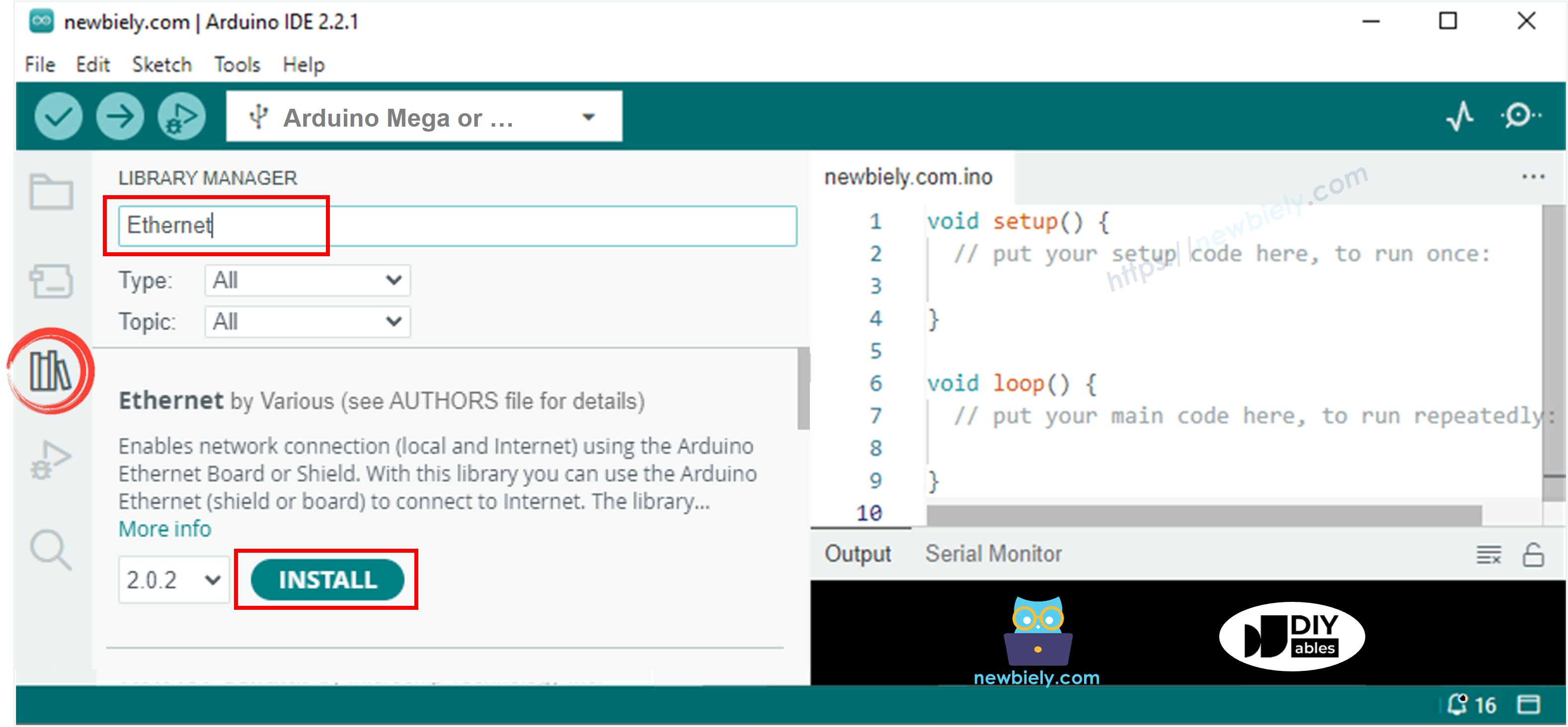
7. Library Installation: The Ethernet library is required for W5500 communication:
- Click the Libraries icon (book icon) on the left sidebar of Arduino IDE
- Type "Ethernet" in the search box
- Locate the Ethernet library by Various (official Arduino library)
- Click the Install button to add the library to your IDE
- Wait for installation to complete
8. Open Serial Monitor: Before uploading code, open the Serial Monitor (Tools → Serial Monitor or Ctrl+Shift+M) and set the baud rate to 9600. This allows you to see the program's output immediately after upload.
9. Copy and Upload Code: Copy the HTTP client code provided above and paste it into a new Arduino IDE sketch. Click the Upload button (right arrow icon) to compile and upload to your Arduino Mega.
10. Verify Network Connection: After upload completes, the Arduino will automatically restart and begin execution. Watch the Serial Monitor for output:
- "Arduino Mega - Ethernet Tutorial" should appear first
- If DHCP succeeds, you'll see "Connected to server"
- The complete HTTP response from example.com will follow
11. Interpret Results: In the Serial Monitor, you should see output similar to this:
Understanding the Output:
- HTTP Status: "HTTP/1.1 200 OK" indicates successful request (200 = success code)
- Response Headers: Lines before blank line contain metadata about the response
- HTML Content: Everything after the blank line is the actual webpage HTML
- "disconnected": Indicates the connection was properly closed
Troubleshooting Tips:
- "Failed to configure Ethernet using DHCP": Check physical network connection, verify router DHCP is enabled
- Nothing prints: Verify Serial Monitor baud rate is set to 9600
- "Connection failed": Check internet connectivity, verify DNS is working
- Timeout errors: Firewall may be blocking outbound connections on port 80
- Random characters: Wrong baud rate in Serial Monitor
※ NOTE THAT:
MAC Address Conflict Warning: Each network device must have a unique MAC address. If another device on your network uses the same MAC address as configured in your Arduino code, both devices will experience intermittent connectivity issues, packet loss, or complete network failure.
The MAC address in the example code (DE:AD:BE:EF:FE:ED) is for demonstration only. For production deployments, use a properly assigned MAC address from your organization's allocated range, or generate a random local MAC address (second hex digit should be 2, 6, A, or E).
Arduino Mega Code for Ethernet Module - Web Server
This example demonstrates how to transform your Arduino Mega into a fully functional web server that responds to HTTP requests from browsers and other HTTP clients. When a browser connects to the Arduino's IP address, the server sends back a simple HTML webpage that displays in the browser.
What This Code Does:
- Server Initialization: Creates an HTTP server listening on port 80 (standard HTTP port)
- Network Setup: Configures Ethernet with MAC address and obtains IP address via DHCP
- Client Detection: Continuously monitors for incoming HTTP connections
- HTTP Response: Sends properly formatted HTTP headers and HTML content to connecting clients
- Connection Management: Handles multiple sequential client connections
- Status Reporting: Displays the assigned IP address in Serial Monitor for easy access
Understanding Web Server Operation:
A web server follows this request-response cycle:
- Listen: Wait for incoming HTTP connections on port 80
- Accept: When browser connects, accept the connection
- Receive: Read the HTTP request from the browser
- Process: Determine what content to send (in this case, simple HTML)
- Respond: Send HTTP headers and HTML content
- Close: Disconnect the client
- Repeat: Return to listening for next connection
This pattern enables Arduino to serve web-based control panels, display sensor data in browsers, create configuration interfaces, provide REST APIs, and act as a networked information display.
Practical Applications:
- Home Automation Dashboard: Control lights, read temperatures, view camera feeds
- Sensor Monitoring: Display real-time sensor readings in web browsers
- Device Configuration: Web-based setup interface for Arduino parameters
- Status Display: Show system health, uptime, or operational status
- Data Visualization: Serve charts and graphs of collected data
- Remote Control: Button/switch controls accessible from any browser
The code below makes the Arduino Mega act as a web server. This server sends a simple webpage to web browsers on the internet.
Detailed Instructions
Follow these steps to deploy your Arduino Mega web server:
1. Verify Wiring: Ensure the W5500 Ethernet module is still properly connected to your Arduino Mega from the previous example (same wiring applies).
2. Network Connection: Verify the Ethernet cable is connected between the W5500 module and your network router/switch.
3. Copy and Upload Code: Copy the web server code provided above and paste it into a new Arduino IDE sketch. Click the Upload button to compile and transfer to your Arduino Mega.
4. Open Serial Monitor: Open the Serial Monitor (Tools → Serial Monitor or Ctrl+Shift+M) and ensure baud rate is set to 9600.
5. Note the IP Address: After upload completes and the Arduino restarts, watch the Serial Monitor. You should see output similar to:
IMPORTANT: Your IP address will likely be different (192.168.1.x or 10.0.0.x depending on your network). Copy the exact IP address shown in YOUR Serial Monitor.
6. Access the Web Server: Open any web browser on a computer or mobile device connected to the same network as your Arduino Mega:
- Paste the IP address from step 5 into the browser's address bar
- Press Enter to navigate to the Arduino web server
- You should see a simple webpage served by your Arduino!
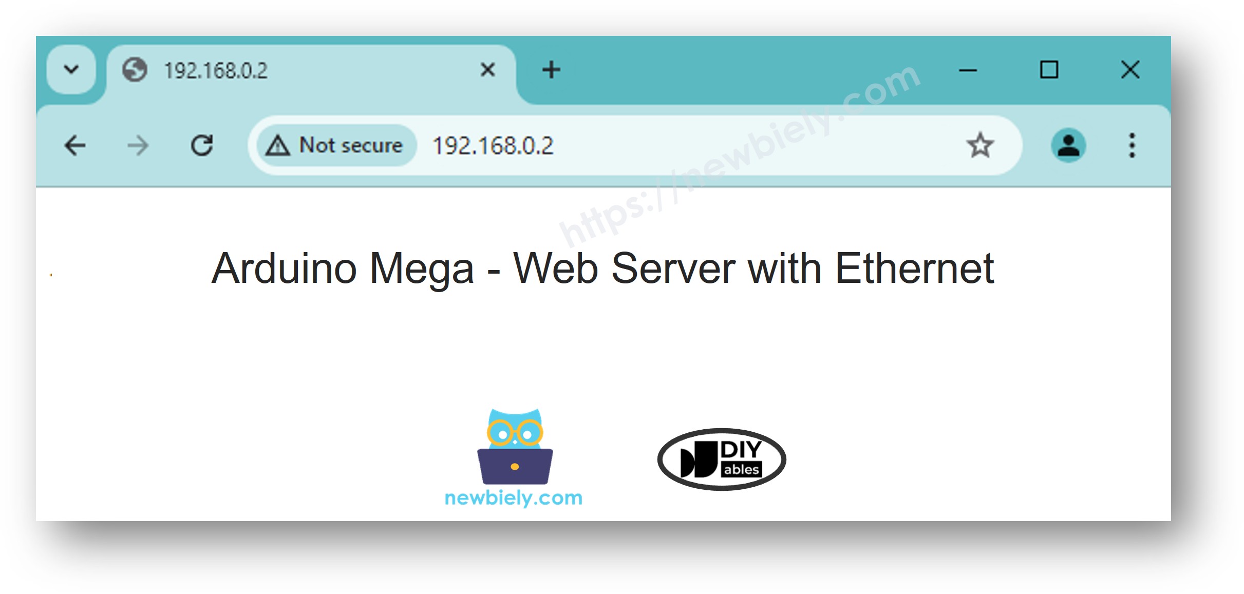
Understanding the Webpage Display:
The HTML code in the Arduino sketch creates a simple webpage with:
- An <h1> header displaying "Arduino Mega Web Server"
- A paragraph explaining this page is served by Arduino Mega
- Basic styling for readability
You can modify the HTML code in the sketch to display sensor values, add buttons that trigger Arduino actions, create forms for user input, or build complete control interfaces.
Advanced Web Server Concepts:
1. Handling Multiple Pages:
Analyze the HTTP request line to serve different content based on the requested URL:
2. Processing Form Data:
Parse POST requests to receive user input from HTML forms and control Arduino pins or settings.
3. JSON API Responses:
Return JSON data instead of HTML for use with JavaScript AJAX requests or mobile apps.
4. Real-Time Updates:
Implement JavaScript auto-refresh or WebSocket connections for live sensor data displays.
Network Access Notes:
- Same Network Only: Devices must be on the same local network to access the Arduino server
- Finding the Arduino: If you forget the IP, check your router's DHCP client list or re-upload the code to see the Serial Monitor output
- Port Forwarding: To access from the internet, configure port forwarding on your router (advanced, security considerations apply)
- Static IP: For permanent installations, configure a static IP in the code instead of DHCP
Troubleshooting Web Server:
- Can't connect to IP: Verify computer and Arduino are on same network, check firewall settings
- IP address not displayed: Check Serial Monitor baud rate, verify DHCP succeeded
- Page doesn't load: Arduino may have lost network connection, restart Arduino
- Blank page: Check HTML code syntax in Arduino sketch
- Slow response: Arduino processes one client at a time; multiple simultaneous connections may cause delays