Arduino Mega - RGB LED
This guide shows you how to use Arduino to control an RGB LED. We will learn in detail:
- How RGB LED works
- How to connect RGB LED to Arduino Mega
- How to connect an RGB LED module to Arduino Mega
- How to program the Arduino Mega to change the color of the RGB LED
Hardware Preparation
Or you can buy the following kits:
| 1 | × | DIYables Sensor Kit (18 sensors/displays) |
Additionally, some of these links are for products from our own brand, DIYables .
Overview of RGB LED
An RGB LED can make many colors by mixing red, green, and blue. It has three tiny LEDs: one red, one green, and one blue. They are all in one small unit.
Pinout
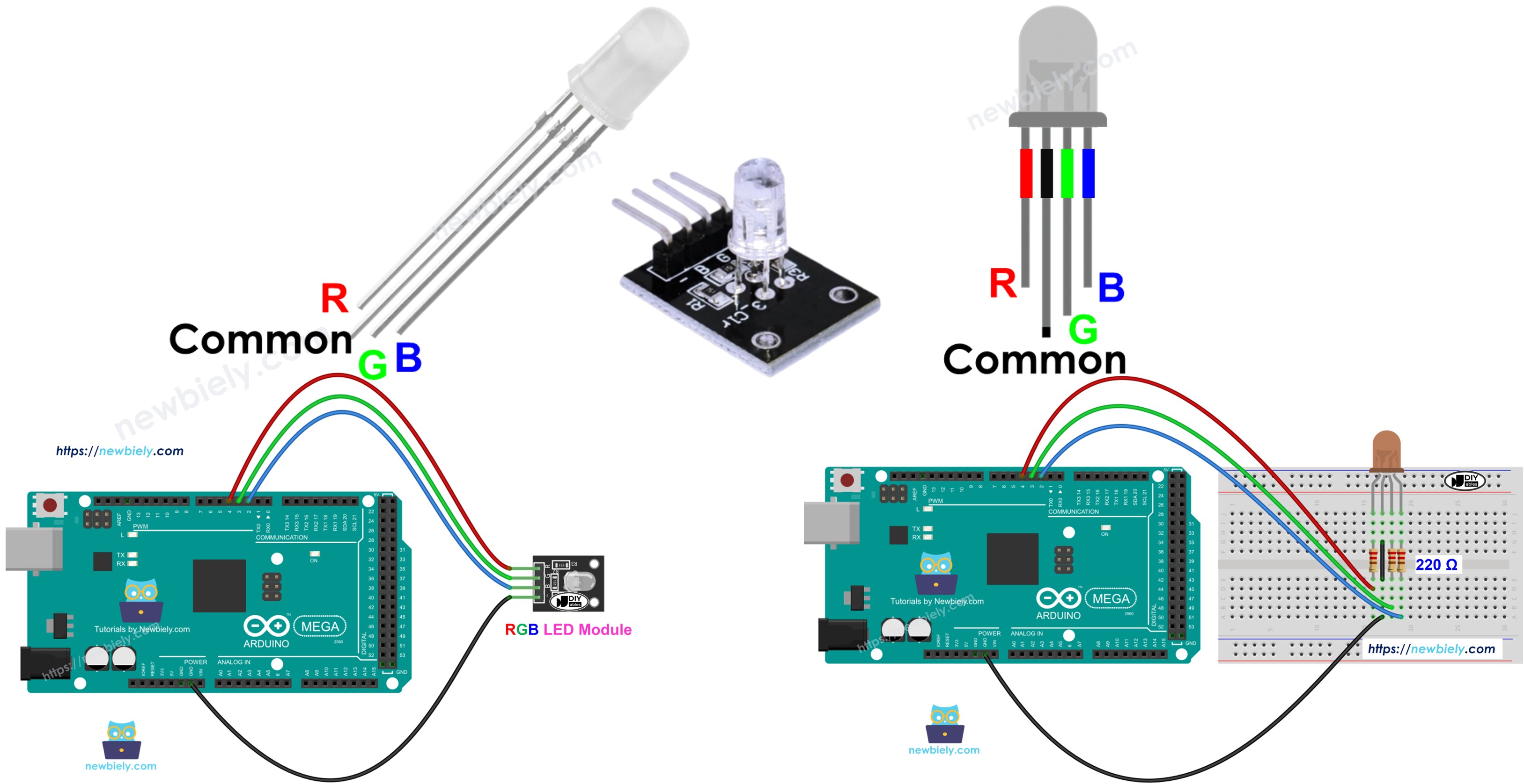
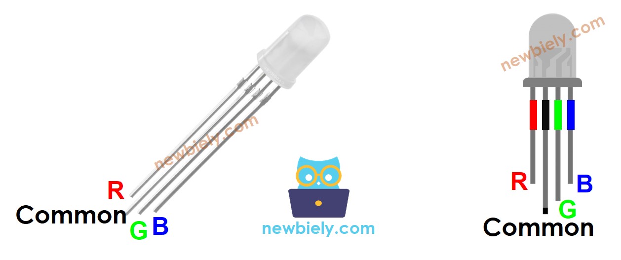
A red-green-blue LED has four pins.
- Connect the common pin to ground (0 volts).
- The R pin sets the red color.
- The G pin sets the green color.
- The B pin sets the blue color.
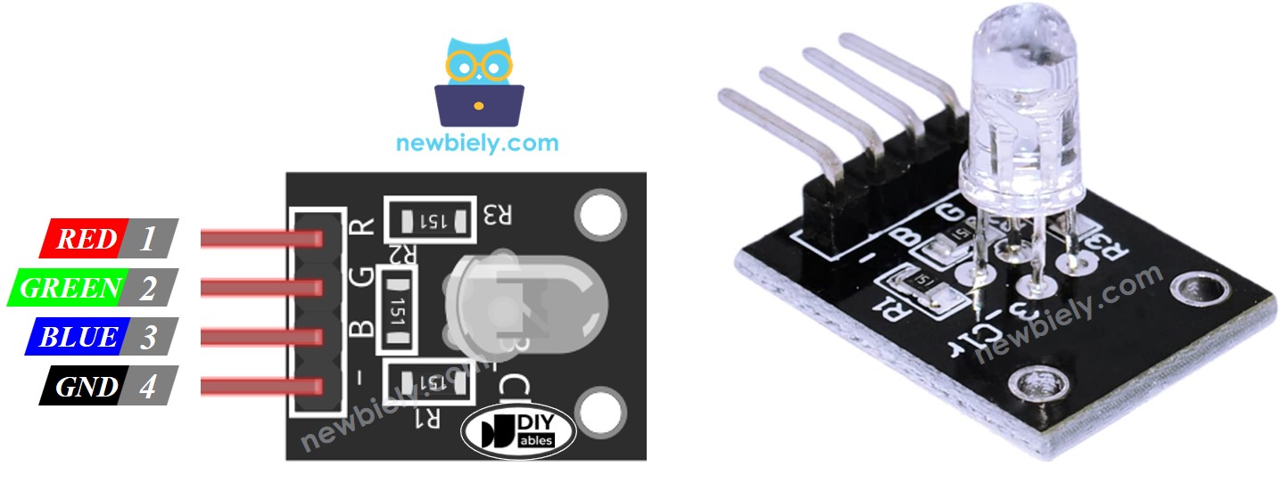
To connect an RGB LED to an Arduino Mega, you need resistors to limit the current, which can make the setup a bit complicated. But you can use the RGB LED module (LINK_MAIN_LED_RGB_MODULE), which already has these resistors built in.
The RGB LED module also has four pins.
- The common pin (cathode) goes to ground (0V).
- The R pin makes the red color.
- The G pin makes the green color.
- The B pin makes the blue color.
※ NOTE THAT:
In this tutorial we use an RGB LED with a common cathode. That means the shared pin is the cathode (the negative side). Some RGB LEDs have the common pin as the anode (the positive side).
How it works
In science, color has three numbers: Red (R), Green (G), and Blue (B). Each number is between 0 and 255.
There are 256 times 256 times 256 colors in total, created by combining three numbers.
If we send PWM signals (fast on/off pulses) to the red, green, and blue pins, the RGB LED can show any color we want. The length of time each signal stays on (the 0–255 value) sets how much red, green, and blue light is used.
Wiring Diagram
- Wiring diagram for connecting an Arduino Mega to an RGB LED.
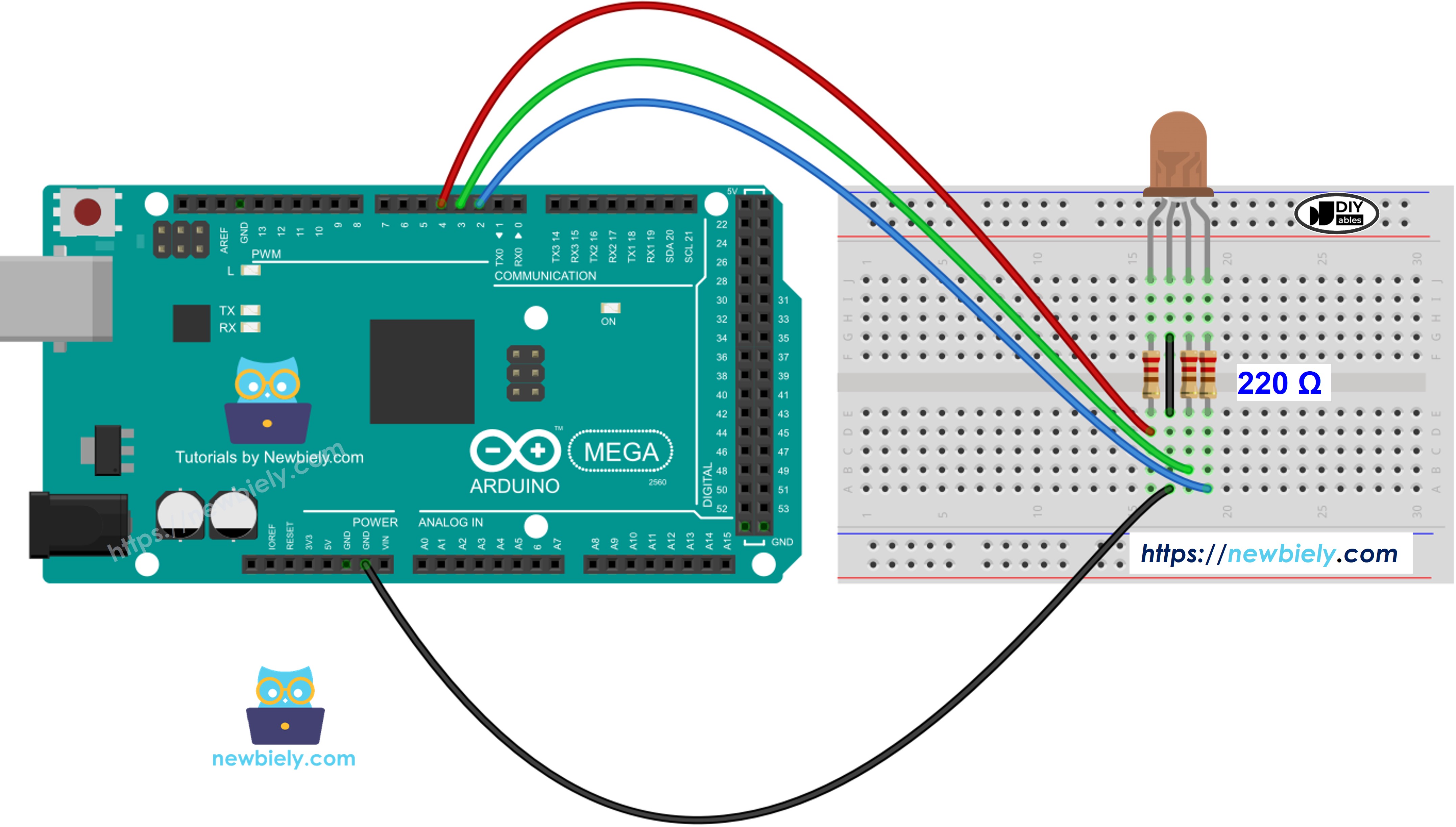
This image is created using Fritzing. Click to enlarge image
Do not use one resistor on the common pin of an RGB LED. Instead, place three resistors—one on each color pin—as shown in the diagram above. The red, green, and blue parts of an RGB LED are not exactly the same, so they do not share current equally. This can cause uneven brightness and could damage the LEDs if you use a single resistor on the common pin.
- Wiring diagram for Arduino Mega to an RGB LED module
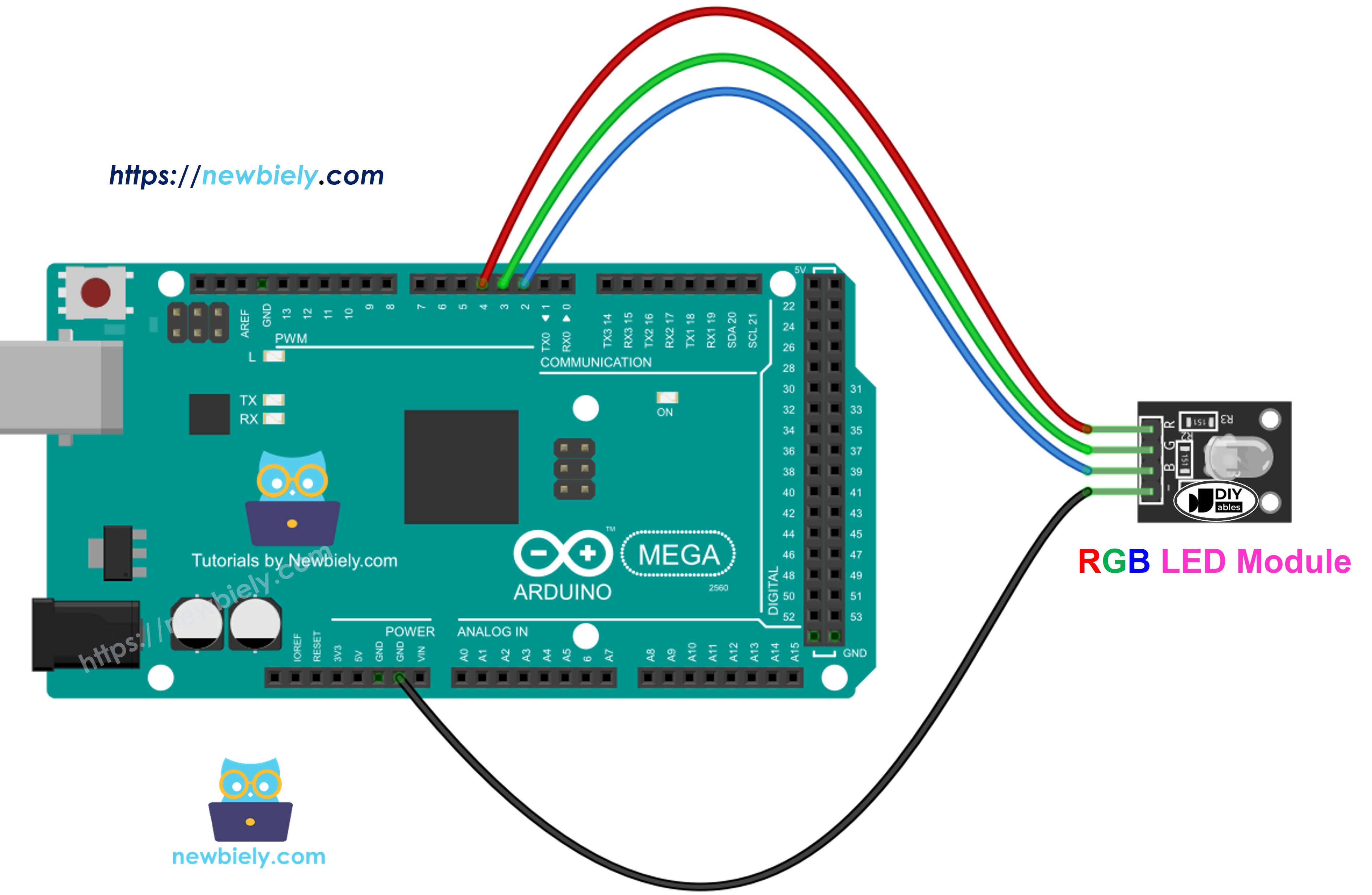
This image is created using Fritzing. Click to enlarge image
How To Control RGB LED
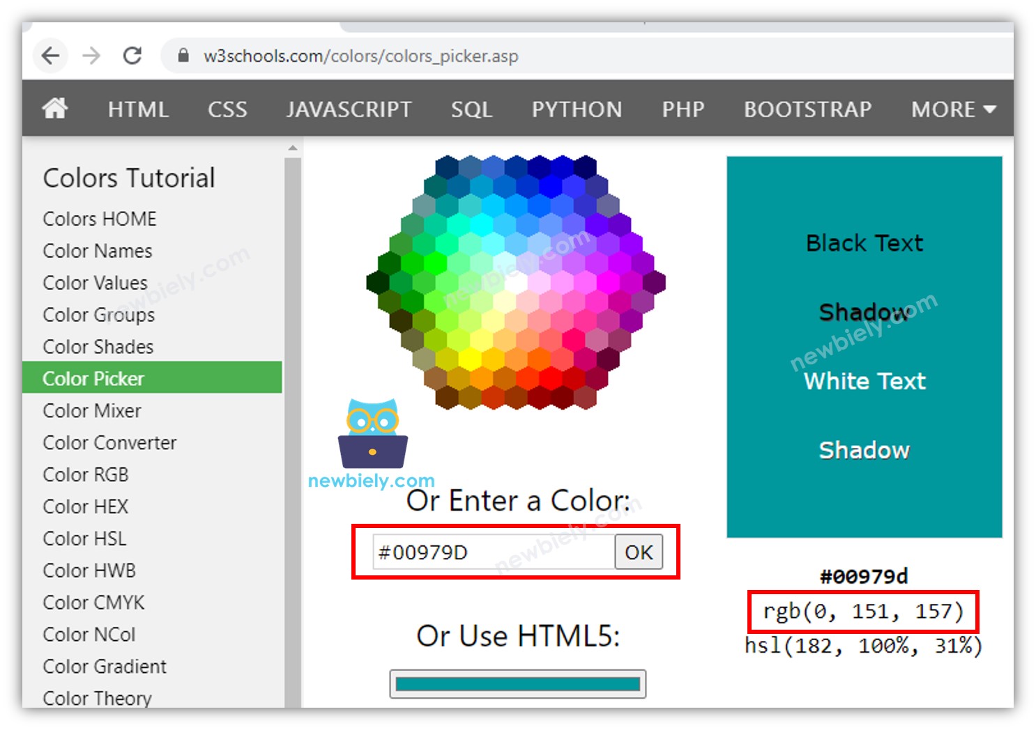
Let's learn, step by step, how to set the RGB LED to any color, for example, the color #00979D.
- Pick the color you want and find its color code.
- You can get a color code from this color picker: color picker.
- If you need a color from a photo, use this Colors From Image tool: Colors From Image.
- Convert the color code to RGB values using this tool: this tool. Remember these values: R = 0, G = 151, B = 157.
- Choose the Arduino Mega pins that connect to the red, green, and blue pins. For example:
- Set these Arduino Mega pins to be outputs.
- Set an Arduino pin to output a PWM signal that shows the color #00979D (R = 0, G = 151, B = 157).
Arduino Mega - RGB LED Example Code
The code shown below changes the LED color in this order:
- Color code #00C9CC, blue-green color. Red 0, Green 201, Blue 204.
- Color code #F7788A, pinkish-red color. Red 247, Green 120, Blue 138.
- Color code #34A853, green color. Red 52, Green 168, Blue 83.
When using many colors, we could shorten the code by creating a function:
Addtional Knowledge
- To set up an RGB LED with a common anode:
- Connect the common pin to the 3.3V pin on the Arduino Mega.
- In the analogWrite() function, set the red, green, and blue values to 255 - R, 255 - G, and 255 - B.
- A group of RGB LEDs connected together makes an RGB LED strip. There are two types of LED strips: addressable and non-addressable. We will provide tutorials for each type.