Arduino Mega - LED - Fade
Ready to create some mesmerizing lighting effects with your Arduino? You're in the perfect place! This comprehensive LED fade tutorial will walk you through everything you need to know about smoothly controlling LED brightness, from basic fading techniques to advanced non-blocking methods that won't interfere with other parts of your code.
Whether you're just starting your Arduino journey or looking to add some professional polish to your lighting projects, this guide has you covered. We'll explore three powerful approaches to LED fading: the simple delay()-based method that's perfect for beginners, the more advanced millis()-based technique that keeps your code running smoothly, and the convenient ezLED library that makes complex effects a breeze.
LED fading is one of those fundamental Arduino skills that opens up a world of creative possibilities. From creating ambient lighting systems and smooth status indicators to building breathing effects for wearable projects and dynamic visual displays, mastering PWM control gives you the foundation for countless exciting projects. Don't worry if terms like "PWM" sound intimidating right now – we'll explain everything in simple, easy-to-understand language.
By the end of this tutorial, you'll not only understand how to fade LEDs but also grasp the important concepts of PWM signals, timing control, and non-blocking code design. These skills will serve you well in more advanced projects involving servo motors, DC motor control, and even audio generation. Let's dive in and bring your LED to life with smooth, professional-looking fading effects that will impress everyone!
In this tutorial, we are going to learn:
- Arduino fades LED by using delay() function
- Arduino fades LED by using millis() function
- Arduino fades LED by using ezLED library
※ NOTE THAT:
This tutorial provides in-depth knowledge that helps you understand the working principle. To make it easy, you can use Arduino - LED library.
Hardware Preparation
Or you can buy the following kits:
| 1 | × | DIYables Sensor Kit (18 sensors/displays) |
Additionally, some of these links are for products from our own brand, DIYables .
Buy Note: Use the LED Module for easier wiring. It includes an integrated resistor.
Overview of LED
An LED (Light Emitting Diode) is a semiconductor component that converts electrical energy into light energy. Think of it as a tiny light bulb that's incredibly efficient, long-lasting, and responds instantly to changes in electrical signals. Unlike traditional incandescent bulbs, LEDs can be precisely controlled using digital signals, making them perfect for Arduino projects where you want dynamic lighting effects.
LEDs are polarized components, which means they only work when connected in the correct direction. They're incredibly versatile and come in various colors, sizes, and brightness levels. What makes LEDs particularly exciting for Arduino projects is their ability to respond to PWM (Pulse Width Modulation) signals, allowing you to create smooth fading effects, precise brightness control, and even complex lighting patterns. They consume very little power, generate minimal heat, and can switch on and off millions of times without wearing out.
The key advantage of LEDs in Arduino projects is their compatibility with PWM control. When you send a PWM signal to an LED, you're essentially turning it on and off very rapidly – so fast that your eyes can't detect the switching. Instead, you perceive this rapid on/off cycling as a steady light with adjustable brightness. This is the principle behind LED fading: by gradually changing the PWM value from 0 to 255, you create a smooth brightness transition that looks completely natural.
Pinout
Let's take a look at the LED pinout – don't worry, it's simpler than it looks! Understanding these connections is key to getting your LED fade project working smoothly. LEDs only have two pins, making them one of the easiest components to work with.
LED includes two pins:
- Cathode(-) pin: This is the negative terminal that needs to be connected to GND (0V). You can identify this pin because it's usually the shorter leg, and the LED housing often has a flat edge on the cathode side. Think of this as the "exit door" for the electrical current.
- Anode(+) pin: This is the positive terminal that's used to control the LED's state and brightness. This pin connects to your Arduino's PWM-capable digital pin. The anode is typically the longer leg and receives the control signal that determines whether the LED is on, off, or somewhere in between.
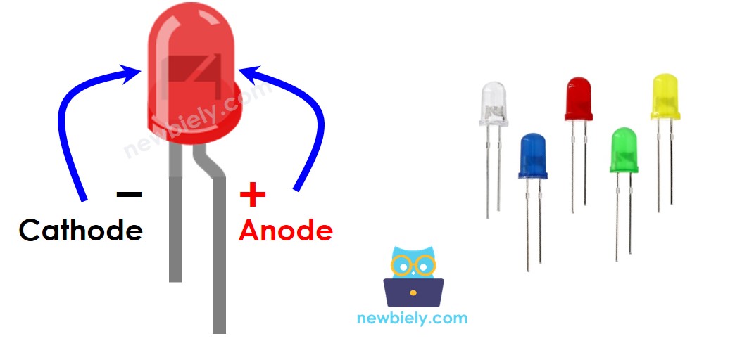
Here's a helpful tip for beginners: if you ever forget which pin is which, remember that the longer leg is always positive (anode), and the shorter leg is negative (cathode). Also, if you look at the LED from above, the flat edge on the plastic housing indicates the cathode side. Getting this connection right is crucial – LEDs won't work (and could be damaged) if connected backwards.
How It Works
Understanding how LEDs respond to different electrical signals is essential for creating smooth fading effects. Here's what happens when you control an LED with your Arduino:
After connecting the cathode(-) to GND:
- If connecting GND to the anode(+): LED is OFF because there's no voltage difference across the LED – it's like having both ends at the same electrical level.
- If connecting VCC to the anode(+): LED is fully ON because there's maximum voltage difference, allowing full current flow through the LED.
- If generating a PWM signal to the anode(+): This is where the magic happens! The brightness of LED changes according to the PWM value, which varies from 0 to 255. The PWM signal rapidly switches between HIGH and LOW states, and your eye perceives the average brightness.
Here's how PWM values translate to brightness levels:
- PWM value 0: Equivalent to connecting GND to the anode, so the LED is completely OFF
- PWM value 255: Equivalent to connecting full VCC to the anode, so the LED is at maximum brightness
- PWM values 1-254: Create intermediate brightness levels – the higher the number, the brighter the LED appears
The beauty of PWM control is that it happens so quickly (usually thousands of times per second) that you don't see any flickering. Instead, you see smooth, consistent brightness that can be adjusted with incredible precision. This is how professional lighting systems work, and now you can create the same effects with your Arduino!
※ NOTE THAT:
For most of LED, it needs to use a resistor between the anode(+) and VCC. The value of the resistor depends on the specification of LED.
Arduino - fade LED
Creating smooth LED fading effects with Arduino is easier than you might think! Some Arduino pins can generate PWM signals, and these are the pins you'll use for fading effects. On the Arduino Mega, you have plenty of PWM-capable pins to work with, giving you lots of flexibility for multi-LED projects.
To fade an LED, you simply connect the LED's anode(+) pin to one of Arduino's PWM-capable pins, connect the LED's cathode(-) to GND through a current-limiting resistor, and then program the Arduino to generate varying PWM signals. The Arduino handles all the complex timing automatically – you just tell it what brightness level you want, and it creates the appropriate PWM signal.
The process is remarkably straightforward: by gradually changing the PWM value in your code (perhaps in a loop that counts from 0 to 255 and back), you create smooth fading transitions that look completely professional. You can control the speed of fading by adjusting how quickly you change the PWM values, create custom fading patterns by using mathematical functions, or even synchronize multiple LEDs for complex lighting effects.
Wiring Diagram
Here's how to connect your LED to the Arduino Mega for smooth fading control. Take your time with the connections – getting the wiring right is crucial for a successful project!

This image is created using Fritzing. Click to enlarge image
| Component Pin | Arduino Pin | Notes |
|---|---|---|
| LED Anode (+) | Pin 9 | Connect through 220Ω resistor |
| LED Cathode (-) | GND | Direct connection to ground |
Important Safety Note: Always use a current-limiting resistor when connecting LEDs to your Arduino. The 220-ohm resistor protects both the LED and your Arduino from excessive current flow. Without this resistor, you could damage your components or create unreliable operation. The resistor value may vary depending on your LED specifications, but 220 ohms works well for most standard LEDs at 5V.
Make sure your connections are secure and double-check the LED polarity before powering up. Remember: longer leg (anode) goes to the Arduino pin through the resistor, shorter leg (cathode) goes directly to GND. If your LED doesn't light up, try flipping it around – it's a common mistake that every Arduino enthusiast makes at least once!
How To Program
Now for the exciting part – let's bring your LED to life with code! Don't worry if you're new to programming; we'll walk through everything step by step. The code for LED fading is surprisingly straightforward once you understand the basic principles.
Programming an Arduino to fade an LED involves two main steps: setting up the pin as an output and then controlling the brightness using PWM values. Here's how it works:
Step 1: Configure an Arduino's pin to digital output mode by using the pinMode() function. For example, to use pin 9:
This tells the Arduino that pin 9 will be sending signals out to control your LED, rather than reading input from a sensor.
Step 2: Set the brightness of your LED by generating the corresponding PWM signal using the analogWrite() function:
Where brightness is a value from 0 to 255. Think of this as a brightness percentage: 0 means completely off, 255 means fully on, and 128 would be about 50% brightness. The Arduino automatically handles all the complex PWM timing for you!
The beauty of this approach is its simplicity – you just specify the brightness level you want, and the Arduino takes care of generating the appropriate electrical signals. To create fading effects, you'll typically use loops or timing functions to gradually change the brightness value over time.
Arduino Code - Fade Example from Arduino IDE
Let's start with the classic Arduino IDE fade example – it's a perfect introduction to LED fading that demonstrates all the core concepts you need to understand.
Detailed Instructions
First time working with Arduino? We recommend checking out our Arduino Getting Started guide - it'll help everything make sense!
- Connect Your Hardware: Carefully wire your LED to the Arduino following the diagram above. Take your time with this step – good connections are the foundation of any successful project.
- Open Arduino IDE: Launch the Arduino IDE on your computer and select the correct board (Arduino Mega) and port from the Tools menu. If you're not sure which port, unplug and replug your Arduino to see which one appears.
- Load the Code: Copy the fade example code below and paste it into a new Arduino sketch. This tried-and-true example has helped thousands of people learn LED fading!
- Upload and Test: Click the Upload button and watch the magic happen. You should see your LED smoothly fade in and out in a gentle, breathing pattern.
- Click Upload button on Arduino IDE to upload code to Arduino

- Enjoy the Results: Watch as your LED smoothly fades in and out! If it's not working, double-check your wiring and make sure the LED isn't inserted backwards.
Pro Tip: If your LED seems too bright or too dim, try adjusting the resistor value. A larger resistor will make it dimmer, while a smaller one will make it brighter. Start with 220 ohms and experiment from there!
Code Explanation
Read the line-by-line explanation in comment lines of code!
How to fade-out LED in a period without using delay()
Now let's level up your skills! The delay()-based approach works fine for simple projects, but what if you want your Arduino to do other things while the LED is fading? That's where non-blocking code comes in. Using the millis() function instead of delay() allows your Arduino to multitask like a pro.
This technique is essential for more complex projects where you might be reading sensors, responding to buttons, or controlling multiple components simultaneously. The key concept is using millis() to track time passage without stopping your program execution. Instead of saying "wait 30 milliseconds," you're saying "check if 30 milliseconds have passed since the last update."
Here's how to create a smooth fade-out effect that doesn't block other code:
This approach gives you much more flexibility and creates smoother, more professional-looking effects. Your Arduino can now handle multiple tasks simultaneously while maintaining perfect fade timing!
How to fade-in LED in a period without using delay()
Creating a smooth fade-in effect follows the same non-blocking principles as fade-out, but we'll reverse the PWM value progression. This technique is incredibly useful for status indicators, ambient lighting, and attention-getting effects in your projects.
The fade-in effect gradually increases the LED brightness from completely off to full brightness over a specified time period. By using millis() for timing control, your Arduino remains responsive to other inputs and can manage multiple tasks simultaneously. This is the foundation for building more complex lighting systems and interactive projects.
With this non-blocking approach, you can easily combine fade-in and fade-out effects, create breathing patterns, or even fade multiple LEDs independently – all while your Arduino continues to monitor sensors or respond to user input!
Challenge Yourself
Ready to take your LED fading skills to the next level? Try these fun challenges that will help you explore new possibilities and deepen your understanding:
Easy Challenges - Perfect for Getting Started:
- Change the Fade Speed: Modify the delay values or timing intervals to create faster or slower fading effects. Try making it breathe like a sleeping person!
- Reverse the Pattern: Start with the LED fully on and fade to off, then back to on again. It's a simple change that creates a completely different visual effect.
- Adjust the Range: Instead of fading from 0 to 255, try fading from 50 to 200 for a more subtle effect that never goes completely dark.
Intermediate Challenges - Time to Stretch Your Skills:
- Multiple LED Fade: Connect 3 LEDs to different PWM pins and make them fade in sequence, like a wave of light moving across your breadboard.
- Button-Controlled Fading: Add a button that starts and stops the fading effect. Hint: Check out our Arduino button tutorials for guidance on reading digital inputs.
- Potentiometer Brightness Control: Use a potentiometer to manually control LED brightness in real-time. Hint: Refer to Arduino - Potentiometer for analog input techniques.
Advanced Challenges - For the Bold and Creative:
- Breathing Effect with Custom Curves: Create more natural-looking breathing patterns using sine waves or custom mathematical functions instead of linear fading.
- Color-Changing RGB LED: Expand to RGB LEDs and create smooth color transitions – imagine fading from red to blue to green and back again!
- Sound-Reactive Fading: Combine with a sound sensor to make LEDs fade in response to music or clapping. This creates amazing interactive lighting effects!
Start with the easy ones and work your way up – don't worry if you get stuck, that's how we learn! Each challenge builds on the previous ones, and before you know it, you'll be creating sophisticated lighting systems that would make professional designers jealous. What will you build first?
Additional Knowledge
Understanding PWM signals opens up a world of possibilities beyond just LED fading! Here are some fascinating insights that will help you become a more well-rounded Arduino developer:
PWM Frequency Matters: The PWM signal generated by analogWrite() function creates smooth LED fading because it operates at a high frequency (around 490Hz for most pins). That's fast enough that your eyes can't detect the individual on/off cycles, so you perceive steady, adjustable brightness. However, if you create a custom function with advanced programming techniques to generate low-frequency PWM signals, the LED will visibly blink instead of fade – this can be useful for creating attention-getting strobe effects or morse code transmissions.
PWM Applications Beyond LEDs: PWM signals are incredibly versatile in Arduino projects. You can use the same analogWrite() function and PWM concepts to control servo motor positions (different PWM values correspond to different angles), adjust DC motor speeds (higher PWM values make motors spin faster), generate audio tones using piezo buzzers (different frequencies create different pitches), and even control heating elements or fans for temperature regulation.
Hardware Considerations: Not all Arduino pins can generate PWM signals – only specific pins have this capability. On the Arduino Mega, pins marked with a "~" symbol (like pins 2-13 and 44-46) can produce PWM output. This is important to remember when planning complex projects with multiple PWM-controlled components.
Power and Current Limits: While LEDs are low-power components, always remember that Arduino pins have current limitations (typically 20mA per pin, 200mA total). For high-power LEDs or multiple LEDs, you'll need to use transistors or dedicated LED driver circuits to handle the additional current safely.
Real-World Applications: The LED fading techniques you've learned are used in professional applications everywhere – from automotive interior lighting and architectural accent lighting to stage effects and smart home systems. You're learning industry-standard concepts that scale up to professional projects!
Function References
- map() - Essential for scaling sensor values to PWM ranges
- millis() - The key to non-blocking timing control
- analogWrite() - Your gateway to PWM control and smooth effects
- pinMode() - Foundation function for configuring Arduino pins